EP1206028A2 - Driving apparatus, power output apparatus, and control method - Google Patents
Driving apparatus, power output apparatus, and control method Download PDFInfo
- Publication number
- EP1206028A2 EP1206028A2 EP01127077A EP01127077A EP1206028A2 EP 1206028 A2 EP1206028 A2 EP 1206028A2 EP 01127077 A EP01127077 A EP 01127077A EP 01127077 A EP01127077 A EP 01127077A EP 1206028 A2 EP1206028 A2 EP 1206028A2
- Authority
- EP
- European Patent Office
- Prior art keywords
- phase
- current
- power supply
- star connection
- voltage
- Prior art date
- Legal status (The legal status is an assumption and is not a legal conclusion. Google has not performed a legal analysis and makes no representation as to the accuracy of the status listed.)
- Granted
Links
Images










Classifications
-
- H—ELECTRICITY
- H02—GENERATION; CONVERSION OR DISTRIBUTION OF ELECTRIC POWER
- H02P—CONTROL OR REGULATION OF ELECTRIC MOTORS, ELECTRIC GENERATORS OR DYNAMO-ELECTRIC CONVERTERS; CONTROLLING TRANSFORMERS, REACTORS OR CHOKE COILS
- H02P6/00—Arrangements for controlling synchronous motors or other dynamo-electric motors using electronic commutation dependent on the rotor position; Electronic commutators therefor
- H02P6/005—Arrangements for controlling doubly fed motors
-
- H—ELECTRICITY
- H02—GENERATION; CONVERSION OR DISTRIBUTION OF ELECTRIC POWER
- H02P—CONTROL OR REGULATION OF ELECTRIC MOTORS, ELECTRIC GENERATORS OR DYNAMO-ELECTRIC CONVERTERS; CONTROLLING TRANSFORMERS, REACTORS OR CHOKE COILS
- H02P6/00—Arrangements for controlling synchronous motors or other dynamo-electric motors using electronic commutation dependent on the rotor position; Electronic commutators therefor
- H02P6/08—Arrangements for controlling the speed or torque of a single motor
-
- H—ELECTRICITY
- H02—GENERATION; CONVERSION OR DISTRIBUTION OF ELECTRIC POWER
- H02P—CONTROL OR REGULATION OF ELECTRIC MOTORS, ELECTRIC GENERATORS OR DYNAMO-ELECTRIC CONVERTERS; CONTROLLING TRANSFORMERS, REACTORS OR CHOKE COILS
- H02P6/00—Arrangements for controlling synchronous motors or other dynamo-electric motors using electronic commutation dependent on the rotor position; Electronic commutators therefor
- H02P6/10—Arrangements for controlling torque ripple, e.g. providing reduced torque ripple
Definitions
- the present invention relates to a driving apparatus, a power output apparatus, and to a control method applicable to these apparatuses.
- Apower output apparatus provided with a capacitor connected between a positive pole bus and a negative pole bus of an inverter circuit for applying a three-phase alternating current to an electric motor and a direct-current power supply connected between the positive pole bus or the negative pole bus of the inverter circuit and a neutral point of an electric motor has been proposed in, for example, Japanese Laid-Open Patent Publications No. Hei 10-337047 and Hei 11-178114.
- the apparatus have the functions of charging the capacitor and driving the electric motor by realizing, by time shearing, the operation of making a circuit composed of coils in each phase of the electric motor and switching devices of the inverter circuit function as a booster chopper circuit for boosting the voltage of the direct-current power supply to charge the capacitor and the operation of making the inverter circuit function as an original circuit for driving the electric motor by the use of the capacitor voltage.
- the voltage input to the inverter circuit i.e. the voltage between the terminals of the capacitor
- the electric motor can effectively be driven if the input voltage to the inverter circuit can be controlled according to the state of the electric motor.
- driving efficiency of the electric motor is limited when the range of the input voltage is limited.
- a driving apparatus, a power output apparatus, and their control method all have an object of controlling an input voltage to their inverter circuits over a wide range. Moreover, the driving apparatus, the power output apparatus, and the control method also aim to more efficiently drive the electric motor.
- an input voltage of its inverter circuit is determined by the neutral point electric potential of each winding group to which a secondary power supply of the driving apparatus is connected, while the neutral point electric potential of a winding group which is a load of a polyphase alternating current and to which the inverter circuit is connected can be varied by the inverter circuit.
- the neutral point electric potential of a winding group which is a load of a polyphase alternating current and to which the inverter circuit is not connected can also be varied by neutral point electric potential control means .
- the input voltage of the inverter circuit can thereby be freely set regardless of the voltage of the secondary power supply.
- the neutral point electric potential control means may be means including an inverter circuit connected with a load of a polyphase alternating current according to the control.
- the load of the plural loads of the polyphase alternating current may be loads equipped by a single electrical apparatus or loads equipped by a plurality of electrical apparatuses.
- a power output apparatus of the present invention by control of two inverter circuits using common positive and negative pole buses, electric power is transferred between a first power supply connected between the positive pole bus and the negative pole bus and a second power supply connected between the neutral points of two star connection coils of an electric motor and polyphase alternating current electric power is supplied to the two star connection coils. Consequently, the voltage between the positive pole bus and the negative pole bus can be controlled over a wide range, and the current to be supplied to the two star connection coils can be controlled. Consequently, the difference in electric potential between the positive pole bus and the negative pole bus, i.e. an input voltage into the two inverter circuits, can be controlled, and the electric motor can therefore be driven more efficiently.
- accumulating means capable of being charged and discharged may be used as the first power supply.
- Accumulating means with a small capacity may be used because the voltage between the terminals of the accumulating means can be controlled.
- the voltage of the first power supply by separately controlling percentage modulations, which are ratios of on-periods of the upper side switching devices and the lower side switching devices of the two inverter circuits.
- percentage modulations are ratios of on-periods of the upper side switching devices and the lower side switching devices of the two inverter circuits.
- the two star connection coils correspondingly to one rotor to constitute an electric motor.
- the two star connection coils correspondingly to severally separated rotors and to form two separated motors.
- the maximum value of a current amplitude to be supplied to one of the star connection coils it is preferable to decrease the maximum value of a current amplitude to be supplied to one of the star connection coils and to add a current corresponding to the decrease amount to a current to be supplied to the other of the star connection coils.
- the maximum value of the current amplitude can be decreased, and the rated voltage and the like of the inverter can be decreased.
- the "electric motor” includes dynamotor capable of generating electrical energy.
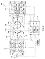
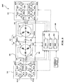
- Fig. 1 is a schematic diagram showing the configuration of a power output apparatus 20 according to an embodiment of the present invention.
- the power output apparatus 20 of the present embodiment is provided with a double-winding motor (hereinafter referred to as a "2Y motor") including two three-phase coils 24, 26 interconnected in a Y (star) connection; two inverter circuits 30, 32 respectively connected with the two three-phase coils 24, 26, and having a positive pole bus 34 and a negative pole bus 36 for common use; a capacitor 38 connected between the positive pole bus 34 and the negative pole bus 36; a direct-current power supply 40 connected between the neutral points of the two three-phase coils 24, 26 of the 2Y motor 22; and an electronic control unit 50 for controlling the entire apparatus.
- a double-winding motor hereinafter referred to as a "2Y motor”
- two inverter circuits 30, 32 respectively connected with the two three-phase coils 24, 26, and having a positive pole bus 34 and a negative pole bus 36 for common use
- a capacitor 38 connected
- Fig. 2 is an explanatory diagram illustrating a relationship between the two three-phase coils 24, 26 of the 2Y motor 22.
- the 2Y motor 22 is composed of a rotor, on the outer surface of which is, for example, affixed a permanent magnet, and a stator equipped with two three-phase coils 24, 26 that are wound in a state of being shifted by angle ⁇ in the rotation direction shown in Fig. 2.
- the structure of the 2Y motor 22 is the same as that of an ordinal synchronous dynamotor capable of producing electric power except for the fact that the two three-phase coils 24, 26 are wound. Because the three-phase coils 24, 26 are shifted from each other by the angle ⁇ in the rotation direction, the 2Y motor 22 can be regarded as a six-phase motor.
- the inverter circuit 32 For the driving of such a 2Y motor 22, the inverter circuit 32 should be driven to apply a three-phase alternating current having a phase difference of a shifted angle ⁇ between windings to a three-phase alternating current to be applied to the three-phase coil 24 by the inverter circuit 30 to the three-phase coils 26.
- the rotation shaft of the 2Y motor 22 is the outputting shaft of the power output apparatus 20 of the embodiment, and power is output from the rotation shaft. Because the 2Y motor of the embodiment is constructed as a dynamotor as described above, electric power can be generated by the 2Y motor 22 as a result of rotation of the rotation shaft of the 2Y motor 22.
- the inverter circuits 30, 32 are respectively composed of six transistors T11-T16, T21-T26, and six diodes D11-D16, D21-D26.
- the six transistors T11-T16, T21-T26 are disposed on the source side and on the sink side between the positive pole bus 34 and the negative pole bus 36 as pairs composed of respective two of them.
- Each of the three-phase coils 24, 26 (U, V, W) of the 2Y motor 22 is connected with each connection point of the pairs.
- the electronic control unit 50 is configured as a microprocessor including a central processing unit (CPU) 52 as a main component, and the unit 50 is provided with a read only memory (ROM) 54 storing processing programs, a random access memory (RAM) 56 for storing data temporarily, and an input-output port (not shown) .
- CPU central processing unit
- ROM read only memory
- RAM random access memory
- the electronic control unit 50 receives the following inputs through the input port; each phase current Iu1, Iv1, Iw1, Iu2, Iv2, Iw2 from each current sensor 61-66 fitted to each of u-, v- and w- phases of the three-phase coils 24, 26 of the 2Y motor 22; a neutral point current Io from a current sensor 67 fitted to the neutral point of the 2Y motor 22; a rotation angle ⁇ of the rotator of the 2Y motor 22 from the rotation angle sensor 68 fitted to the rotation shaft of the 2Y motor 22; a voltage between the terminals of the capacitor 38 from a voltage sensor 70 fitted to the capacitor 38; command values concerning the driving of the 2Y motor 22; and the like.
- any one current sensor in each group of the current sensors 61-63 and 64-66 can be omitted, and any one current sensor in each of the groups may be used as a sensor for detecting abnormality.
- the electronic control unit 50 outputs control signals for performing the switching control of the transistors T11-T16, T21-T26 of the inverter circuits 30, 32 and the like through the output port.
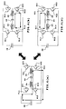
- FIGs. 3(a), 3(b) and 3(c) are explanatory diagrams for illustrating current flows in a state such that the electric potential difference Vo12 between the neutral point of the three-phase coil 24 and the neutral point of the three-phase coil 26 is made smaller than the voltage Vb of the direct-current power supply 40 by referring leakage inductance in the u-phase of the three-phase coils 24, 26 of the 2Y motor 22.
- the transistor T12 in the inverter circuit 30 or the transistor T21 in the inverter circuit 32 is turned on in a state such that the electric potential difference Vo12 between the neutral point of the three-phase coil 24 and the neutral point of the three-phase coil 26 is smaller than the voltage Vb of the direct-current power supply 40.
- a short circuit shown by an arrow of a continuous line in Fig. 3(a) or Fig. 3(b) is formed, and the u-phase of the three-phase coils 24, 26 of the 2Y motor 22 functions as a reactor.
- the circuit can be regarded as a capacitor charging circuit for charging the capacitor 38 with the energy of the direct-current power supply 40. Because the capacitor charging circuit has the same configuration as that of a booster chopper circuit, the voltage Vc between the terminals of the capacitor 38 can be freely operated to be higher than the voltage Vb of the direct-current power supply 40.
- the capacitor 38 can be charged by the direct-current power supply 40 by making the electric potential difference Vol2 between the neutral point of the three-phase coil 24 and the neutral point of the three-phase coil 26 be smaller than the voltage Vb of the direct-current power supply 40 and by turning on or off the transistors T12, T14, T16 of the inverter circuit 30 and the transistors T21, T23, T25 of the inverter circuit 32.
- Figs. 4(a), 4(b) and 4(c) are explanatory diagrams for illustrating current flows in a state such that the electric potential difference Vo12 between the neutral point of the three-phase coil 24 and the neutral point of the three-phase coil 26 is larger than the voltage Vb of the direct-current power supply 40 by referring leakage inductance in the u-phase of the three-phase coils 24, 26 of the 2Y motor 22.
- the transistor T11 in the inverter circuit 30 is turned on, the transistor T12 in the inverter circuit 30 and the transistor T21 in the inverter circuit 32 are turned off, and the transistor T22 in the inverter circuit 32 is turned on in a state such that the electric potential difference Vo12 between the neutral point of the three-phase coil 24 and the neutral point of the three-phase coil 26 is larger than the voltage Vb of the direct-current power supply 40.
- a short circuit shown by an arrow of a continuous line in Fig. 4 (a) is formed, and the direct-current power supply 40 is charged by the voltage Vc between the terminals of the capacitor 38.
- the u-phase of the three-phase coils 24, 26 of the 2Y motor 22 functions as a reactor as described above.
- the transistor T11 in the inverter circuit 30 or the transistor T22 in the inverter circuit 32 are turned off, the energy stored in the u-phase of the three-phase coils that functions as a reactor charges the direct-current power supply 40 through a charging circuit shown by an arrow of a continuous line in Fig. 4(b) or Fig 4(c). Consequently, the circuit can be regarded as a direct-current power supply charging circuit for charging the energy of the capacitor 38 into the direct-current power supply 40.
- the direct-current power supply 40 can be charged by the capacitor 38 by making the electric potential difference Vo12 between the neutral point of the three-phase coil 24 and the neutral point of the three-phase coil 26 larger than the voltage Vb of the direct-current power supply 40 and by turning on or off the transistors T11-T16 of the inverter circuit 30 and the transistors T21-T26 of the inverter circuit 32.
- the power output apparatus 20 of the embodiment can charge the capacitor 38 with the direct-current power supply 40 and can charge the direct-current power supply 40 with the capacitor 38, the voltage Vc between the terminals of the capacitor 38 can be controlled to be a desired value.
- the inverter circuits 30, 32 enter a state such that a direct-current power supply from the capacitor 38 is connected between their positive pole bus 34 and the negative pole bus 36, and the voltage Vc between the terminals of the capacitor 38 operates as an inverter input voltage Vi. Accordingly, through switching control of the transistors T11-T16, T21-T26 of the inverter circuits 30, 32, driving of the 2Y motor 22 can be controlled.
- the electric potential Vu1, Vv1, Vw1 of eachphase of a three-phase alternating current applied to the three-phase coil 24 can be freely set within the range of the inverter input voltage Vi using the switching control of the transistors T11-T16 in the inverter circuit 30, and the electric potential Vu2, Vv2, Vw2 of each phase of a three-phase alternating current applied to the three-phase coil 26 can be freely set in the range of the inverter input voltage Vi by the switching control of the transistors T21-T26 in the inverter circuit 32.
- Figs. 5(a) and 5(b) show examples of the waveforms of electric potential Vu1, Vv1, Vw1 (Fig. 5(a)) of each phase of the three-phase coil 24 and the waveforms of electric potential Vu2, Vv2, Vw2 (Fig.
- ⁇ designates the aforesaid phase difference based on the shifted angle between windings and Vx designates a median (Vi/2) of the inverter input voltage Vi.
- the voltage of the capacitor 38 can be charged by the operation of the electric potential difference Vo12 between the neutral points of the three-phase coils 24, 26 of the 2Y motor 22 to be lower than the voltage Vb of the direct-current power supply 40, or, contrarily, the direct-current power supply 40 can be charged by the operation of the electric potential difference Vo12 between the neutral points of the three-phase coils 24, 26 to be higher than the voltage Vb of the direct-current power supply 40.
- the charging current of the capacitor 38 and the charging current of the direct-current power supply 40 can be controlled by the rising and the falling of the electric potential difference Vo12 between the neutral points of the three-phase coils 24, 26.
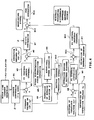
- Fig. 6 is a block diagram showing the driving control performed in the electronic control unit 50 of the power output apparatus 20 of the present embodiment as control blocks.
- the control blocks are composed of a current conversion section M1 for performing the three-phase to two-phase conversion of motor line currents Iu1, Iv1, Iw1, Iu2, Iv2, Iw2 detected by the current sensors 61-63, 64-66 by the use of the rotation angle ⁇ of the rotator of the 2Y motor 22 detected by the rotation angle sensor 68; a subtracter M2 for operating deviations ⁇ Id, ⁇ Iq of current command values Id*, Iq* input as one command value concerning the driving of the 2Y motor 22 from currents Id, Iq after the three-phase to two-phase conversion by the current conversion section M1; a PI control section M3 for operating operation amounts for motor current adjusting to the deviations ⁇ Id, ⁇ Iq by the use of PI gains
- the blocks to the three-phase coils 24 and the blocks to the three-phase coil 26 are indicated as the same blocks.
- the configuration from the current conversion section M1 to the two-phase to three-phase conversion section M7 and the current conversion sectionM14 is the same as that for ordinarymotor control
- the operation of the PWM signal by the addition of the electric potential difference Vo12 between the neutral points operated by the components from the subtracter M8 to the PI control section M12 to each phase electric potential Vu1, Vv1, Vw1, Vu2, Vv2, Vw2 obtained by the two-phase to three-phase conversion section M7 three-phase alternating currents to be imposed on the three-phase coils 24, 26 can be set as waveforms offset from the median Vx as exemplified in Fig. 5 in order to maintain the voltage Vc of the capacitor 38 as the inverter
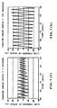
- Figs. 7(a) and 7(b) show example simulated results of current ripples when phase angles of a carrier wave are 0 degrees (Fig. 7(a)) and 180 degrees (Fig. 7(b)) under the conditions that the frequency is 100Hz, the voltage Vc of the capacitor 38 is 400V, the voltage Vb of the direct-current power supply 40 is 100V, the shifted angle ⁇ between windings are 30 degrees, and the current command values Id*, Iq* are severally 0A. As shown in the diagrams, the current ripples become smaller when the phase angle of the carrier wave is 0 degrees.
- the voltage Vc between the terminals of the capacitor 38 as the inverter input voltage Vi can be flexibly controlled. Consequently, because the inverter input voltage Vi can be freely adjusted according to the driving states of the 2Y motor 22, the 2Y motor 22 can be more efficiently driven than when the inverter input voltage Vi is limited within a predetermined range or the case where the inverter input voltage Vi is fixed at a predetermined voltage. Moreover, because the voltage Vb of the direct-current power supply 40 can be freely selected, the degree of freedom of the designing of the direct-current power supply 40 is remarkably increased.
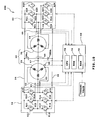
- the present embodiment may also be configured using a modified power output apparatus 20B as shown in Fig. 8; a first motor 22A including a three-phase coil 24B;and a second motor 22B including a three-phase coil 26B.
- rotation angle sensors 68A, 68B for detecting rotation angles ⁇ a, ⁇ b of respective rotators are provided to the first motor 22A and the second motor 22B, and a three-phase alternating current applied to the first motor 22A by the inverter circuit 30 is controlled by the rotation angle ⁇ a from the rotation angle sensor 68A.
- control of a three-phase alternating current applied to the second motor 22B by the inverter circuit 32 is based on the rotation angle ⁇ b from the rotation angle sensor 68B.
- driving of each of the first motor 22A and the second motor 22B can be independently controlled.
- the power output apparatus 20B being a modification, has two output shafts of the rotation shaft of the first motor 22A and the rotation shaft of the second motor 22B.
- capacitor 38 is connected between the positive pole bus 34 and the negative pole bus 36 in the power output apparatuses 20 and 20B, a direct-current power supply may be connected in place of the capacitor 38.
- the power output apparatus 20C may be configured such that a capacitor 38Ca is connected between the positive pole bus 34 and the neutral point of the three-phase coil 24 and a capacitor 38Cb is connected between the neutral point of the three-phase coil 26 and the negative pole bus 36.
- a capacitor 38Ca is connected between the positive pole bus 34 and the neutral point of the three-phase coil 24
- a capacitor 38Cb is connected between the neutral point of the three-phase coil 26 and the negative pole bus 36.
- the power output apparatus 20D may be configured such that a capacitor 38Da is connected between the positive pole bus 34 and the neutral point of the three-phase coil 24 and a capacitor 38Db is connected between the neutral point of the three-phase coil 24 and the negative pole bus 36. Still further, as exemplified in a power output apparatus 20E shown in Fig. 11, the power output apparatus 20E may be configured such that a capacitor 38Ea is connected between the positive pole bus 34 and the neutral point of the three-phase coil 26 and a capacitor 38Eb may be connected between the neutral point of the three-phase coil 26 and the negative pole bus 36.
- an electric potential difference sensor may be provided between the positive pole bus 34 and the negative pole bus 36 for detecting the electric potential difference between the buses, or the electric potential difference of each capacitor may be detected.
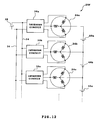
- the direct-current power supply 40 is connected between the neutral points of the two three-phase coils 24, 26 to which electric power is supplied by two inverter circuits 30, 32, as exemplified in a power output apparatus 20F shown in Fig. 12, the power output apparatus 20F may be configured such that each neutral point of three three-phase coils or more 24a, 24b, 24c ... to which electric power is supplied by three inverter circuit 30a, 30b, 30c ... or more may be connected in series with direct-current power supplies 40a, 40b, 40c ....
- the direct-current power supply 40 is connected between the neutral points of the two three-phase coils 24, 26, the coils are not limited to three-phase coils, and a direct-current power supply may be connected between the neutral points of a polyphase alternating current coil.
- the power output apparatus 20 has been described as a power output apparatus equipped with a double-winding motor, it is obvious that the present invention can also be applied to an apparatus that does not output power, as long as the apparatus variably controls the input voltage of an inverter circuit.
- a direct-current power supply is disposed between neutral points of two polyphase coils and the switching of inverters for controlling power supply to the two polyphase coils.
- a capacitor voltage being a power supply of the two inverters is controlled.
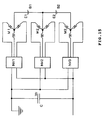
- the 2YDC system of the embodiment When the 2YDC system of the embodiment is redrawn by the omission of the inside of the inverters, the 2YDC system can be expressed as shown Fig. 13.
- one end of a capacitor C is connected with a power source (e.g. earth) of a fixed voltage. Then, both the ends of the capacitor C are respectively connected with an inverter INV1 and an inverter INV2. As such, the output of the capacitor C is input into the inverters INV1, INV2 as an input.
- a power source e.g. earth
- the inverter INV1 has three-phase outputs U1, V1, W1 to which three-phase coils of U, V, W of a motor coil M1 are respectively connected.
- the inverter INV2 has three-phase outputs U2, V2, W2 to which three-phase coils of U, V, W of a motor coil M2 are respectively connected.
- the motor coils M1, M2 are separately shown, the motor coils M1, M2 are in fact coils of one motor.
- the motor coils M1, M2 are disposed in a motor to differ from each other by a predetermined angle, and electric currents different from each other in phase by the predetermined angle are supplied to the motor coils M1, M2.
- both currents to be supplied to both the motor coils M1, M2 function as motor driving currents.
- Each phase motor coil of the motor coils M1, M2 is commonly connected at neutral points, and the neutral points of the motor coils M1, M2 are connected to each other through a battery B.
- the positive pole of the battery B is connected to the neutral point of the motor coil M1
- the negative pole of the battery B is connected to the neutral point of the motor coil M2.
- the inverters INV1, INV2 severally have three arms composed of a series connection of two switching transistors disposed between a first power supply "p” and a second power supply "m" (the first power supply "p” is earth in the shown example), and the central points of these arms are connected with the end of each phase coil.
- the inverters INV1, INV2 are driven by a voltage (output voltage) Vc of both the terminals of the capacitor C as a power supply. Then, a voltage (output voltage) E of both the ends of the battery B does not basically change. Accordingly, by control of the zero-phase currents, the central point electric potential of the motor coils M1, M2 can be arbitrarily set while the difference by the voltage of the battery B is maintained.
- the u-phase current is iu1; the v-phase current is iv1; the w-phase current is iw1; the u-phase end voltage is Vu1; the v-phase end voltage Vv1; and the w-phase end voltage Vw1.
- the u-phase current is iu2; the v-phase current is iv2; the w-phase current is iw2; the u-phase end voltage is Vu2; the v-phase end voltage Vv2; and the w-phase end voltage is Vw2.
- the neutral point voltage of the motor coil M1 is Vz1; the neutral point voltage of the motor coil M2 is Vz2; the battery B voltage is E; and the zero-phase current is ie.
- the inverters INV1, INV2 control the neutral point electric potential Vz1, Vz2 of the motor coils M1, M2 by controlling the switching transistors therein by the PWM control.
- the ratios (percentage modulations) of the on-periods of the upper side transistors and the on-periods of the lower side transistors are the ratios of the amplitudes of voltage command values to a period of a carrier wave being a triangular wave. That is, when the voltage command value is made to be higher, the period during which the triangular wave exceeds the command value decreases to that degree.
- Fig. 14(a) shows the percentage modulation d1 of the inverter INV1
- Fig. 14(b) shows the percentage modulation d2 of the inverter INV2.
- the capacitor voltage Vc can be determined by the control of the percentage modulations of the two inverters INV1, INV2.
- the switching transistors are turned on or off without a dead time to the carrier frequency Ts of the inverters. That is, when the duty ratio is 50 %, both the upper and the lower transistors are turned on for the period of 50%.
- Td dead times during which both the upper and the lower transistors are turned off are interposed for eliminating any passthrough current during switching periods completely.
- the capacitor voltage Vc can be determined by the control of the percentage modulations d1, d2.
- Fig. 15 shows a still further modification.
- This example includes three motor coils M1, M2, M3, wherein the neutral points of the motor coils M1, M2 are connected with a battery B1, and the neutral points of the motor coils M2, M3 are connected with a battery B2. Additionally, the outputs of an inverter INV1 are connected with the motor coil M1; the outputs of an inverter INV2 are connected with the motor coil M2; and the outputs of an inverter INV3 are connected with the motor coil M3. Then, the inputs of the inverters INV1, INV2, INV3 are connected with both the ends of a capacitor C.
- motor coils M1, M2, M3, if four motor coils or more are provided similar control can be executed.
- a plurality of motor coils may constitute one electric motor, or may constitutes a plurality of electric motors.
- phase current iu1 of one phase (hereupon u-phase) is divided into an average value (direct-current component) idc per one rotation and the other components (alternating-current components) iac.
- alternating-current components iac a function normalized by their amplitudes Iac is introduced.
- a voltage Vw is defined on the basis of the relation between the battery voltage E and the capacitor voltage Vc of the present system. This is done because, forthe amplitude Iac of the phase current, the voltage obtained by the subtraction of the battery voltage E from the capacitor voltage Vc assumes the maximum value. Moreover, it is assumed that voltages vv which are simultaneously applied to each coil change with a fixed phase difference (power factor cos ⁇ ) from the aforesaid electric current iac.
- Vw Vc - E
- Vv Vwg( ⁇ + ⁇ )
- the relation between the motor output Wo and the work performed by each coil because there are six coils, the relation can be arranged as follows.
- the battery voltage E 42V or 105V.
- the power factor cos ⁇ 0.8. Differences of the maximum values of alternating-current amplitudes to the motor output Wo owing to conducting methods under these conditions are shown.
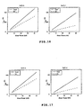
- Fig. 16 to Fig. 18 show the differences of the phase current maximum values resulting from boosting rates.
- the abscissa indicate motor outputs
- the ordinate indicate phase current maximum values (imax).
- Continuous lines indicate phase current maximum values
- broken lines indicate direct-current components (ie/3) of the phase current maximum values.
- Fig. 16 shows conventional phase current maximum values at the time of current supplying
- Fig. 17 shows the phase current maximum values at the time of conducting while the maximum values are suppressed under the condition of being inadmissible of zero-phase ripples
- Fig. 18 shows the phase current maximum values in case of a maximum suppressing conducting method (4. 2. 2. nodes) under the condition of being admissible of zero-phase ripples.
- the sizes of the phase currents vary greatly according to the boosting rates.
- phase currents iu1, iv1, iw1, iu2, iv2, iw2, which are ordinarily flown in the 2Y DC variable type inverter shown in Fig. 13, can be expressed by the following formulae.
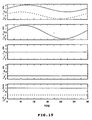
- each step in Fig. 19 shows the following: a first step from the top shows each electric current iu1, iu2; a second step shows the summation of the currents iu1, iu2; a third step shows d-axis currents id1, id2 after the d-q axis conversion of the phase current; a fourth step shows q-axis currents iq1, iq2; and the final step shows one third (for one phase) of the zero-phase current ie.
- iq1 + iq2 is a current component that contributes to motor torque (because a magnetic position is not included in the analysis in the present case, it can also be said that iu1 + iu2 is the current component that contributes to the motor torque) , and ie is an electric current flowing between a battery and a capacitor. Then, the maximum value of the phase current at this time is 2.00 (A).
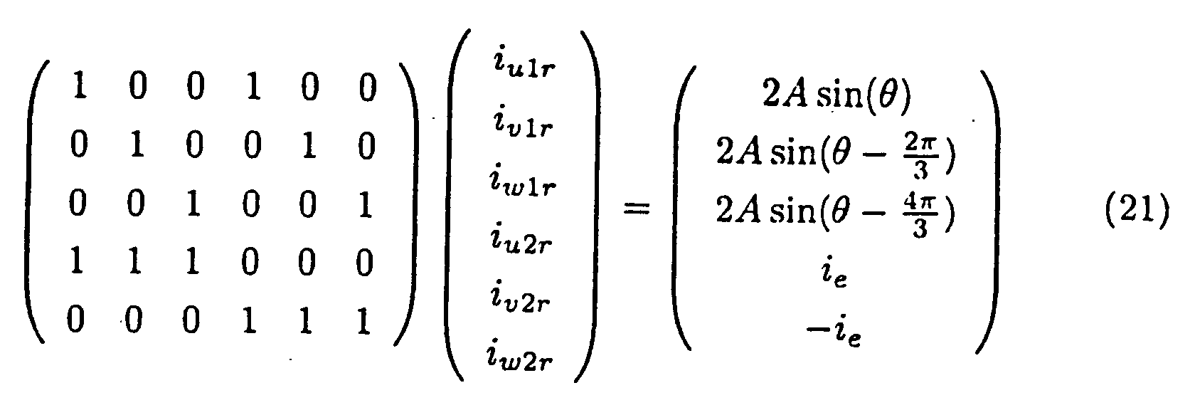
- the condition of an electric current for generating motor driving torque and an electric current between the battery and the capacitor can be written as formula (21).
- Fig. 17 suppresses the maximum values of phase currents while preventing generation of ripples in a zero-phase current.
- the configuration of the preferred embodiment suppresses the maximum amplitudes by adding a predetermined function to phase currents iu1, iv1, iw1 in the 2Y DC variable type inverter of Fig. 13. Then, the maximum amplitudes of electric currents is supressed without changing the output torque of a motor by subtracting the added function from the phase currents iu2, iv2, iw2. Moreover, ripples in the zero-phase current are prevented.
- phase currents iu1, iv1, iw1, iu2, iv2, iw2 satisfy the relation expressed in formula (21). That is,the phase currents must satisfy the following formula (32).
- This formula indicates that summation of the electric currents of the corresponding phases of each star connection results in a sine wave, and that the sum total of the current of each phase in each star connection is equal to the value of the zero-phase current or the value of the zero-phase current having the opposite sign.
- fu( ⁇ ), fv( ⁇ ), fw( ⁇ ) are parameters with 2 degrees of freedom and capable of being utilized for design purposes.
- phase currents iu1, iv1, iw1, iu2, iv2, iw2 can be changed without the changes of the output torque and the zero-phase current. Then, by selection of parameters fu( ⁇ ), fv( ⁇ ), fw( ⁇ ) so as to decrease the maximum amplitudes of the phase currents iu1, iv1, iw1, iu2, iv2, iw2, the desired results can be achieved.
- Fig. 18 relaxes the conditions in order to permit the generation of ripples in the zero-phase current and thereby suppress the maximum values of phase currents.
- the condition of the formula (39) can be removed, which further widens the degree of freedom for selection of the parameters fu( ⁇ ), fv( ⁇ ), fw( ⁇ ), which in turn enables further restraint the maximum values of the phase currents.
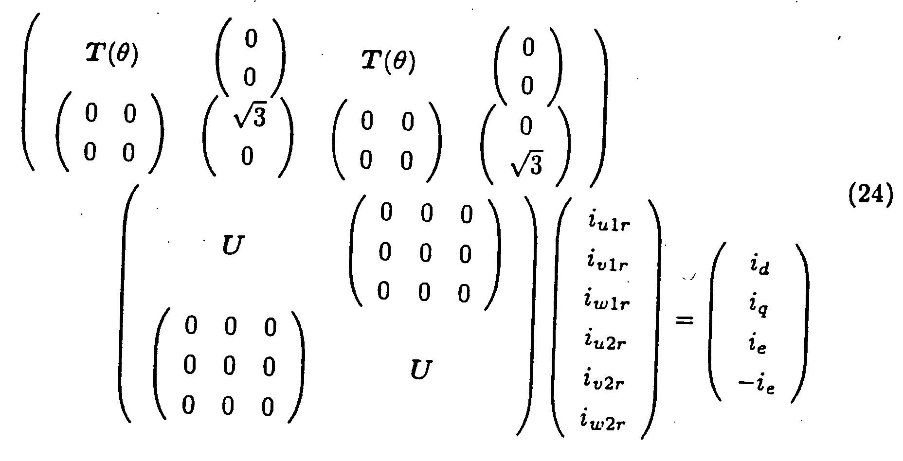
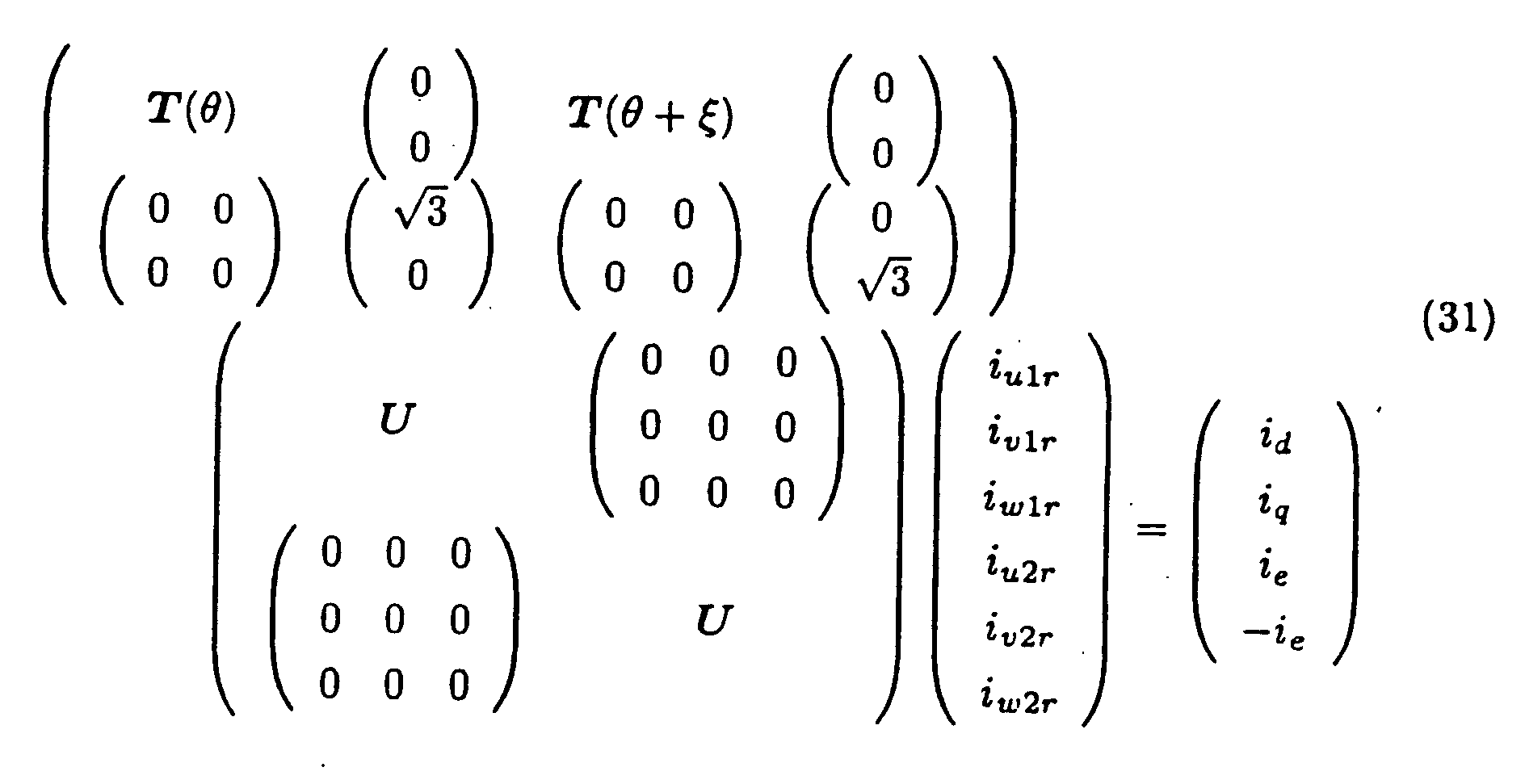
- the formula (31) replaces formula (21). That is, for the decrease of current amplitudes without the change of the largeness of motor generation torque and the zero-phase current, it is necessary for the phase currents u1, iv1, iw1, iu2, iv2, iw2 to satisfy a formula (43).
- This formula shows that the summation of the corresponding d-q axis current of each star connection is constant, and that the sum total of each phase current in each star connection is equal to the value of the zero-phase current or the value of the zero-phase current or the value of the zero-phase current having an opposite sign.
- the phase currents iu1, iv1, iw1, iu2, iv2, iw2 can be changed without altering the output torque and the zero-phase current.
- the parameters fu( ⁇ ), fv( ⁇ ), fw( ⁇ ), hu( ⁇ ), hv( ⁇ ), hw( ⁇ ) to suppress the maximum values of the phase currents iu1, iv1, iw1, iu2, iv2, iw2, additional desired results can be achieved.
- a conducting method meeting the aforesaid conditions when the phase difference between coils ⁇ is 0 degrees can be obtained by the setting of the parameters fu( ⁇ ), fv( ⁇ ), fw( ⁇ ) to formulae (60)-(62), wherein g1 in the formulae is a constant inserted to satisfy formulae (40)-(42).
- g1 0.867.
- the scales of the ordinate axes of the diagram of the parameter fu( ⁇ ) and the diagram of the current iu1 are set equal.
- the waveform of the parameter fu( ⁇ ) is enlarged for ease of viewing.
- the waveform of the parameter fu( ⁇ ) takes a form such that peak portions of a sine wave are cut for widths of 60 degrees to be arranged in the order of the positive side, negative side, and positive side, and such that the negative amplitude is set to be twice the positive amplitude. That is, the waveform is one such that the maximum peaks of the current iu1 are mostly suppressed.
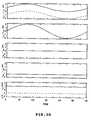
- the zero-phase current ie is 3(A), and the current includes no ripple components.
- the current (iu1 + iu2)for generating motor torque is the same as that shown in Fig. 19, and the current generates the intended torque.
- phase currents The maximum value of the phase currents is 1.866(A).
- the breakdown of the size is that the alternating-current component is 0.866A and the direct-current component is 1A.
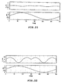
- the waveform of the parameter fu( ⁇ ) in the case where the alternating-current amplitude A is 1(A) and the zero-phase current ie is 3(A) is shown in Fig. 24 in comparison with the waveform of the u-phase current iu1.
- the waveform is a sine wave having the amplitude of the original alternating-current waveform and a frequency three-times that of the original waveform.
- Fig. 24 shows the parameter fu( ⁇ ). Moreover, the results of the usage of the parameter fu( ⁇ ) are shown in Fig. 25. From the figure, the following can be known.
- the average value of the zero-phase current ie is 3 (A) .
- the amplitude thereof is three times that of the added parameter fu( ⁇ ).
- the current (iu1 + iu2) that generates motor torque is the same as that shown in Fig. 19, and the intended torque is generated.
- phase currents 1.872(A), wherein the alternating-current component is 0.872A and the direct-current component is 1A.
- the zero-phase current ie is 3(A), and does not include any ripple component.
- the currents (id and iq) for generating motor torque are the same as those shown in Fig. 19, and the intended torque is generated.
- phase currents The maximum value of the phase currents is 1.866(A), wherein the alternating-current component is 0.866A and the direct-current component is 1A.
- the command value used in this example has a steeply changing waveform for suppressing the size of electric currents.
- the waveform is realized by the filtering of the command value to remove the high frequency components. In such a case, the effect of suppressing electric currents deteriorates slightly.
- the average value of the zero-phase current ie is 3(A)This current includes a 0.46A ripple component.
- the current (iu1 + iu2) for generating motor torque is the same as that shown in Fig. 19, and the current generates the intended torque.
- phase currents The maximum value of the phase currents is 1.63 (A), wherein the alternating-current component is 0.63A and the direct-current component is 1A.
- the average value of the zero-phase current ie is 3(A), which includes ripple components.
- the size of the ripple components is three times as large as that of the added parameter fu( ⁇ ).
- the current (iu1 + iu2) that generates motor torque is the same as one shown in Fig. 19, and the intended torque is generated.
- phase currents The maximum value of the phase currents is 1.96(A), wherein the alternating-current component is 0.96A and the direct-current component is 1A.
- the maximum current value of phase currents can be suppressed without increasing or decreasing torque, and the current capacity of a device can be decreased without affecting the performance of themotor. Consequently, cost of the system can be reduced while performance is maintained. Moreover, by suppressing torque ripples, the functions of a motor can be maintain as a sufficient level.
Landscapes
- Engineering & Computer Science (AREA)
- Power Engineering (AREA)
- Control Of Ac Motors In General (AREA)
- Inverter Devices (AREA)
Abstract
Description
Consequently, the electric potential Vo1 at the neutral point of the three-phase coil 24 of the 2Y motor 22 and the electric potential Vo2 at the neutral point of the three-phase coil 26 of the 2Y motor 22 can be flexibly controlled. Figs. 5(a) and 5(b) show examples of the waveforms of electric potential Vu1, Vv1, Vw1 (Fig. 5(a)) of each phase of the three-phase coil 24 and the waveforms of electric potential Vu2, Vv2, Vw2 (Fig. 5(b)) of each phase of the three-phase coil 26 when the difference between the electric potential Vo1 at the neutral point of the three-phase coil 24 and the electric potential Vo2 at the neutral point of the three-phase coil 26 is operated to be equal to the voltage Vb of the direct-current power supply 40. In the diagrams, α designates the aforesaid phase difference based on the shifted angle between windings and Vx designates a median (Vi/2) of the inverter input voltage Vi. Accordingly, the voltage of the capacitor 38 can be charged by the operation of the electric potential difference Vo12 between the neutral points of the three-phase coils 24, 26 of the 2Y motor 22 to be lower than the voltage Vb of the direct-current power supply 40, or, contrarily, the direct-current power supply 40 can be charged by the operation of the electric potential difference Vo12 between the neutral points of the three-phase coils 24, 26 to be higher than the voltage Vb of the direct-current power supply 40. The charging current of the capacitor 38 and the charging current of the direct-current power supply 40 can be controlled by the rising and the falling of the electric potential difference Vo12 between the neutral points of the three-phase coils 24, 26.



















Claims (18)
- A driving apparatus characterized by:a plurality of polyphase alternating current loads including a winding group;an inverter circuit connected with one of said plural polyphase alternating current load;at least secondary power supply connected between neutral points of a winding group of the polyphase alternating current load to which said inverter circuit is connected and at least one winding group of a polyphase alternating current load different from said polyphase alternating current load; andat least one neutral point electric potential control apparatus for controlling electric potential at a neutral point of a winding group included in a polyphase alternating current load to which said inverter circuit is not connected among said polyphase alternating current loads to which said secondary power supply is connected.
- The driving apparatus according to claim 1, wherein said neutral point electric potential control apparatus comprises an inverter circuit connected to the polyphase alternating current load to be controlled.
- The driving apparatus according to claim 1 or 2, wherein said plural polyphase alternating current loads are loads equipped to a single electrical apparatus.
- A power output apparatus capable of outputting power, said apparatus characterized by:wherein said power output apparatus outputs the power by flowing an electric current through said two star connection coils.two star connection coils;two inverter circuits having a positive pole bus and a negative pole bus for common use, said inverter circuits being capable of supplying polyphase alternating current power to each of at least said two star connection coils;a first power supply connected with said positive pole bus and said negative pole bus; anda second power supply connected between neutral points of said two star connection coils,
- The power output apparatus according to claim 4, wherein said first power supply is a storage device capable of charging and discharging.
- The power output apparatus according to claim 5, wherein said two inverter circuits severally include a plural series connections of upper side switching devices and lower side switching devices, both devices being disposed between said positive pole bus and said negative pole bus, and connection points of said upper side switching devices and said lower side switching devices are severally connected with a plurality of terminals of corresponding star connection coils, and
said power outputting apparatus controls a voltage of said first power supply by controlling percentage modulations being ratios of on-periods of said upper side switching devices and said lower side switching devices in said two inverter circuits. - The power output apparatus according to claim 6, wherein said power output apparatus severally controls the percentage modulations in said two inverters on a basis of the formula Vc = Vb/(d1 - d2), where d1 designates a percentage modulation of one of said two inverters; d2 designates a percentage modulation of the other of said two inverters; Vb designates an output voltage of said second power supply; and Vc designates an output voltage of said first power supply.
- The power output apparatus according to claim 7, wherein said the formula used as a basis for control is modified in consideration of a dead time during which all switching devices in the plural series connections of the upper side switching devices and the lower side switching devices in said two inverters are being turned off in a case where the dead time is set.
- The power output apparatus according to claim 8, wherein said modified formula is Vc = Vb/{(d1-Td/Ts) - (d2+Td/Ts)}, where Ts designates a period of a carrier wave to determine on- and off-periods in said two inverters, and Td designates said dead time in one period of the carrier wave.
- The power output apparatus according to anyone of claims 4-9, wherein said two star connection coils are provided correspondingly to one rotor to constitute one electric motor.
- The power output apparatus according to claim 10,
wherein said apparatus performs switching control of a plurality of switching devices of said two inverter circuits such that a phase difference between each polyphase alternating current power to be supplied to said two star connection coils of said electric motor equals a phase difference of said two star connection coils, a desired torque is output from said electric motor, and a voltage of said first power supply is held at an object voltage. - The power output apparatus according to any one of claims 4-9, wherein said two star connection coils are provided correspondingly to separated rotors to constitute two separated electric motors.
- The power output apparatus according to claim 12, wherein said apparatus performs switching control of a plurality of switching devices of each of said two inverter circuits in order that desired torque is output from each of said two electric motors while a voltage of said first power supply is maintained at an object voltage.
- The power output apparatus according to claim 10, wherein said apparatus decreases an amplitude maximum value of the electric current to be supplied to one of said star connection coils and adds an electric current corresponding to an amount of the decreased amplitude maximum value to the electric current to be supplied to another of said star connection coils.
- The power output apparatus according to claim 14, wherein said apparatus determines the amount of the decreased amplitude maximum value and the adding of the electric current under a condition that output torque of said electric motor remains constant.
- The power output apparatus according to claim 15, wherein said apparatus determines the amount of the decreased amplitude maximum value and the adding of the electric current under a condition that an influence to an electric current flowing between said neutral points of said two star connection coils is not generated.
- A method for controlling a power output apparatus including an electric motor having two star connection coils; two inverter circuits having a positive pole bus and a negative pole bus for common use, said inverter circuits being capable of supplying polyphase alternating current power to each of said two star connection coils; a storage device connected between said positive pole bus and said negative pole bus; and a power supply connected between neutral points of said two star connection coils of said electric motor, said method characterized by a step of:performing switching control of a plurality of switching devices of said two inverter circuits such that a phase difference between each polyphase alternating current power to be supplied to said two star connection coils of said electric motor is equal a phase difference between said two star connection coils in a state such that an electric potential difference between said neutral points of said two star connection coils can be adjusted, whereby desired torque is output from said electric motor and an electric potential difference between said positive pole bus and said negative pole bus is made to be a desired electric potential difference.
- A method for controlling a power output apparatus including a first electric motor having a star connection coil, a second electric motor having a star connection coil, a first inverter circuit capable of supplying polyphase alternating current power to said first electric motor, a second inverter circuit having positive and negative pole buses being positive and negative pole buses of said first inverter circuit, said second inverter circuit being capable of supplying polyphase alternating current power to said second electric motor, a storage device connected between said positive and negative pole buses of said first inverter circuit, and a power supply connected between a neutral point of said first electric motor and a neutral point of said second electric motor, said method characterized by a step of:performing switching control of a plurality of switching devices of said first inverter circuit and said second inverter circuit in a state such that an electric potential difference between said neutral point of said first electric motor and said neutral point of said second electric motor can be adjusted, whereby desired torque is output from said first electric motor, desired torque is output from said second electric motor, and an electric potential difference between said positive pole bus and said negative pole bus is made to be a desired electric potential difference.
Applications Claiming Priority (4)
| Application Number | Priority Date | Filing Date | Title |
|---|---|---|---|
| JP2000346967 | 2000-11-14 | ||
| JP2000346967 | 2000-11-14 | ||
| JP2001331175A JP3721116B2 (en) | 2000-11-14 | 2001-10-29 | DRIVE DEVICE, POWER OUTPUT DEVICE, AND CONTROL METHOD THEREOF |
| JP2001331175 | 2001-10-29 |
Publications (3)
| Publication Number | Publication Date |
|---|---|
| EP1206028A2 true EP1206028A2 (en) | 2002-05-15 |
| EP1206028A3 EP1206028A3 (en) | 2003-05-14 |
| EP1206028B1 EP1206028B1 (en) | 2008-08-20 |
Family
ID=26603958
Family Applications (1)
| Application Number | Title | Priority Date | Filing Date |
|---|---|---|---|
| EP01127077A Expired - Lifetime EP1206028B1 (en) | 2000-11-14 | 2001-11-14 | Driving apparatus, power output apparatus, and control method |
Country Status (4)
| Country | Link |
|---|---|
| US (1) | US6630804B2 (en) |
| EP (1) | EP1206028B1 (en) |
| JP (1) | JP3721116B2 (en) |
| DE (1) | DE60135427D1 (en) |
Cited By (12)
| Publication number | Priority date | Publication date | Assignee | Title |
|---|---|---|---|---|
| CN101902185A (en) * | 2009-05-28 | 2010-12-01 | 通用汽车环球科技运作公司 | Control method of operating, system and the equipment of two interchanges (AC) motor |
| CN101357595B (en) * | 2007-07-30 | 2012-02-22 | 通用汽车环球科技运作公司 | Series-coupled two-motor drive using double-ended inverter system |
| FR2966303A1 (en) * | 2010-10-18 | 2012-04-20 | Renault Sa | Electrical rotating machine i.e. electric motor for electric vehicle, has control unit controlling stator circuit, where control unit is arranged to apply determined set point to stator circuit to reduce acoustic disturbances of machine |
| CN101357596B (en) * | 2007-07-30 | 2012-05-02 | 通用汽车环球科技运作公司 | System using a multiphase electric machine with a double-ended inverter system |
| CN102474106A (en) * | 2009-06-30 | 2012-05-23 | 松下电器产业株式会社 | Power distribution system |
| CN102545429A (en) * | 2010-12-07 | 2012-07-04 | 株式会社电装 | Motor system |
| CN105429536A (en) * | 2014-09-12 | 2016-03-23 | 乐金电子研发中心(上海)有限公司 | Integrated starting power generation system |
| CN106452209A (en) * | 2016-12-07 | 2017-02-22 | 江苏理工学院 | Synchronous driving control device of double-permanent-magnet brushless motor |
| EP2928061A4 (en) * | 2012-11-28 | 2017-03-08 | Fuji Electric Co., Ltd. | Power conversion system and method for controlling same |
| EP1946956A4 (en) * | 2005-09-21 | 2017-05-03 | Toyota Jidosha Kabushiki Kaisha | Device for controlling electric power, electric vehicle with the same, and power control method of electric vehicle |
| CN110915125A (en) * | 2017-07-28 | 2020-03-24 | 罗伯特·博世有限公司 | Method for determining the rotor position of a rotating electrical machine and rotating electrical machine for carrying out such a method |
| CN117162866A (en) * | 2022-05-27 | 2023-12-05 | 通用汽车环球科技运作有限责任公司 | Systems and methods for reducing battery ripple losses |
Families Citing this family (59)
| Publication number | Priority date | Publication date | Assignee | Title |
|---|---|---|---|---|
| US6518736B2 (en) * | 2000-06-26 | 2003-02-11 | Toyota Jidosha Kabushiki Kaisha | Mechanical power outputting apparatus and inverter apparatus |
| JP4023171B2 (en) * | 2002-02-05 | 2007-12-19 | トヨタ自動車株式会社 | LOAD DRIVE DEVICE, CHARGE CONTROL METHOD FOR POWER STORAGE DEVICE IN LOAD DRIVE DEVICE, AND COMPUTER-READABLE RECORDING MEDIUM CONTAINING PROGRAM FOR CAUSING COMPUTER TO EXECUTE CHARGE CONTROL |
| DE10215822B4 (en) * | 2002-04-10 | 2013-03-07 | Sew-Eurodrive Gmbh & Co. Kg | Inverter system and procedure |
| JP2004015892A (en) * | 2002-06-05 | 2004-01-15 | Toshiba Corp | Inverter control device and electric vehicle |
| WO2004008602A1 (en) * | 2002-07-12 | 2004-01-22 | Toyota Jidosha Kabushiki Kaisha | Method and system for detecting the disconnection of an auxiliary power supply from a poly-phase motor |
| JP3896047B2 (en) * | 2002-07-26 | 2007-03-22 | 株式会社豊田中央研究所 | Motor drive control device |
| FR2843248B1 (en) * | 2002-07-30 | 2005-01-14 | Moving Magnet Tech Mmt | METHOD FOR CONTROLLING SYNCHRONIZED OPERATION OF AT LEAST TWO POLYPHASE ELECTRIC MOTORS |
| JP4153760B2 (en) * | 2002-09-18 | 2008-09-24 | 株式会社豊田中央研究所 | Motor circuit and motor control method |
| JP4138423B2 (en) * | 2002-09-25 | 2008-08-27 | 株式会社豊田中央研究所 | Power output device |
| JP4138430B2 (en) * | 2002-09-27 | 2008-08-27 | 株式会社豊田中央研究所 | Inverter system |
| JP4016819B2 (en) * | 2002-12-02 | 2007-12-05 | 株式会社豊田自動織機 | Inverter device, drive control device, and drive control method |
| JP2004236424A (en) | 2003-01-30 | 2004-08-19 | Toyota Motor Corp | POWER OUTPUT DEVICE, MOTOR DRIVE METHOD, AND COMPUTER-READABLE RECORDING MEDIUM RECORDING PROGRAM FOR CAUSING COMPUTER TO EXECUTE DRIVE CONTROL OF MOTOR |
| JP2004336885A (en) | 2003-05-07 | 2004-11-25 | Toyota Motor Corp | POWER OUTPUT DEVICE, MOTOR DRIVE METHOD, AND COMPUTER-READABLE RECORDING MEDIUM RECORDING PROGRAM FOR CAUSING COMPUTER TO EXECUTE DRIVE CONTROL OF MOTOR |
| US7102305B2 (en) * | 2003-05-22 | 2006-09-05 | Toyoda Koki Kabushiki Kaisha | Apparatus and method for controlling motor |
| US6911810B2 (en) * | 2003-07-11 | 2005-06-28 | Wilsun Xu | Reduction of energization transients in a three phase Y-connected load |
| JP2005045879A (en) * | 2003-07-24 | 2005-02-17 | Toyota Motor Corp | Power output unit and computer readable recording medium recording program for executing motor drive control in computer |
| JP3969385B2 (en) * | 2003-11-27 | 2007-09-05 | 日産自動車株式会社 | Control device and control method for motor-driven 4WD vehicle |
| JP4446439B2 (en) * | 2004-05-25 | 2010-04-07 | 本田技研工業株式会社 | Portable generator |
| JP4113527B2 (en) | 2004-11-25 | 2008-07-09 | トヨタ自動車株式会社 | Power output apparatus and vehicle equipped with the same |
| JP4679891B2 (en) * | 2004-11-30 | 2011-05-11 | トヨタ自動車株式会社 | AC voltage generator and power output device |
| JP4635710B2 (en) | 2005-05-11 | 2011-02-23 | トヨタ自動車株式会社 | AC voltage output device |
| JP4742781B2 (en) * | 2005-09-28 | 2011-08-10 | トヨタ自動車株式会社 | AC voltage output device and hybrid vehicle equipped with the same |
| JP4337797B2 (en) | 2005-09-29 | 2009-09-30 | トヨタ自動車株式会社 | Power control device and electric vehicle |
| JP4491434B2 (en) * | 2006-05-29 | 2010-06-30 | トヨタ自動車株式会社 | Power control device and vehicle equipped with the same |
| JP4179351B2 (en) * | 2006-07-07 | 2008-11-12 | トヨタ自動車株式会社 | Power supply system, vehicle equipped with the same, method for controlling power supply system, and computer-readable recording medium recording a program for causing computer to execute control of power supply system |
| EP2149187A1 (en) * | 2007-05-23 | 2010-02-03 | TM4 Inc. | Multiple phase electric motor and drive |
| US7786690B2 (en) * | 2007-08-17 | 2010-08-31 | Oriental Motor Co., Ltd. | Motor control apparatus |
| JP4380755B2 (en) | 2007-10-10 | 2009-12-09 | 株式会社デンソー | Rotating electrical machine equipment |
| US8125168B2 (en) * | 2007-11-19 | 2012-02-28 | Honeywell International Inc. | Motor having controllable torque |
| WO2009081840A1 (en) * | 2007-12-25 | 2009-07-02 | Nabtesco Corporation | Motor unit and gear power transmission device |
| JP5220182B2 (en) * | 2009-03-05 | 2013-06-26 | 三菱電機株式会社 | Insulation deterioration detector |
| JP5412974B2 (en) * | 2009-03-13 | 2014-02-12 | 株式会社デンソー | Driving device for three-phase AC synchronous motor |
| US8405341B2 (en) * | 2009-04-13 | 2013-03-26 | Panasonic Corporation | Synchronous electric motor system |
| JP5304427B2 (en) * | 2009-05-14 | 2013-10-02 | 株式会社デンソー | Rotating electrical machine drive system |
| US8228014B2 (en) * | 2009-07-30 | 2012-07-24 | GM Global Technology Operations LLC | Multi-phase DC/DC boost converter |
| KR101543039B1 (en) * | 2009-10-26 | 2015-08-10 | 현대자동차주식회사 | Method of Circuit Configuration of Inverter Capacitor Module Using Impedance Matching Method |
| CN101976999B (en) * | 2010-11-30 | 2012-05-02 | 中国汽车技术研究中心 | Three-leg nine-switch inverter for dual AC motor drives |
| US8648559B2 (en) * | 2011-03-16 | 2014-02-11 | Deere & Company | System for controlling rotary electric machines to reduce current ripple on a direct current bus |
| JP2013219869A (en) * | 2012-04-05 | 2013-10-24 | Denso Corp | Controller of rotary machine |
| US8908354B2 (en) * | 2012-07-13 | 2014-12-09 | Associated Research Technologies, Inc. | Electrical instrument having configurable input terminal block |
| JP5672278B2 (en) * | 2012-08-29 | 2015-02-18 | 株式会社デンソー | Control device for three-phase rotating machine |
| US9783070B2 (en) | 2014-02-14 | 2017-10-10 | Jabil Circuit, Inc. | Charge transfer system |
| JP6285290B2 (en) * | 2014-06-17 | 2018-02-28 | 株式会社Soken | Power converter |
| KR20180008860A (en) * | 2015-06-11 | 2018-01-24 | 케이에스알 아이피 홀딩스 엘엘씨. | Modulation techniques for polyphase machines |
| DE102015216007A1 (en) * | 2015-08-21 | 2017-02-23 | Lenze Drives Gmbh | drive system |
| DE102015114640A1 (en) | 2015-09-02 | 2017-03-02 | Rwth Aachen | Circuit arrangement for linking different voltage levels and electrical control methods |
| DE102016119892B4 (en) * | 2015-10-21 | 2022-04-28 | Denso Corporation | Control device for a rotating electrical machine |
| CN106936361A (en) * | 2017-04-18 | 2017-07-07 | 沈阳永磁电机制造有限公司 | A kind of pure square-wave motor control system of multi-phase permanent |
| DE102017126704B4 (en) * | 2017-11-14 | 2022-04-21 | Dr. Ing. H.C. F. Porsche Aktiengesellschaft | Energy transfer in the zero system |
| JP2019103266A (en) * | 2017-12-04 | 2019-06-24 | 株式会社デンソー | Control device for multiple-coil rotary machine |
| US11387764B2 (en) * | 2018-07-12 | 2022-07-12 | Zunum Aero, Inc. | Multi-inverter system for electric machine |
| KR102872739B1 (en) * | 2018-08-07 | 2025-10-16 | 타우 모터스, 인크. | Electric motors |
| DE102018006915A1 (en) * | 2018-08-30 | 2020-03-05 | eMoSys GmbH | Permanently excited electrical machine |
| EP3663871B1 (en) | 2018-12-06 | 2026-02-18 | The Swatch Group Research and Development Ltd | Motor drive unit of a dc electric motor |
| US10784810B1 (en) * | 2019-04-29 | 2020-09-22 | Allegro Microsystems, Llc | Motor controller with accurate current measurement |
| JP7276244B2 (en) * | 2020-05-12 | 2023-05-18 | 株式会社デンソー | Control device for polyphase rotating machine |
| CN112332687A (en) * | 2020-10-28 | 2021-02-05 | 哈尔滨工业大学 | A current source inverter and control strategy for suppressing common mode voltage and eliminating the influence of overlapping current region |
| CN113676106B (en) * | 2021-08-09 | 2023-07-11 | 南京航空航天大学 | Position-free method for double-sleeve winding high-frequency injection of six-phase permanent magnet motor |
| DE102021131791A1 (en) * | 2021-12-02 | 2023-06-07 | Audi Aktiengesellschaft | Method for operating an electrical circuit arrangement comprising at least a first component and a second component, an electrical circuit arrangement and a motor vehicle |
Family Cites Families (12)
| Publication number | Priority date | Publication date | Assignee | Title |
|---|---|---|---|---|
| JPS6066655A (en) * | 1983-09-19 | 1985-04-16 | Fukuo Shibata | Structure of rotary electric machine |
| US4641066A (en) * | 1984-10-04 | 1987-02-03 | Nippondenso Co., Ltd. | Control apparatus for brushless motor |
| JPS6455076A (en) | 1987-08-26 | 1989-03-02 | Fuji Electric Co Ltd | Feeding system using polyphase multiple pwm inverter |
| US5099186A (en) | 1990-12-31 | 1992-03-24 | General Motors Inc. | Integrated motor drive and recharge system |
| JPH0538182A (en) | 1991-07-24 | 1993-02-12 | Hitachi Ltd | Elevator equipment |
| JP3399134B2 (en) * | 1994-12-12 | 2003-04-21 | 株式会社明電舎 | Operation control device for pole number switching motor |
| JP3331881B2 (en) * | 1995-12-21 | 2002-10-07 | 三菱電機株式会社 | Inverter device, compressor |
| JP3000953B2 (en) * | 1997-03-21 | 2000-01-17 | トヨタ自動車株式会社 | Power output device and control method thereof |
| JP3223842B2 (en) | 1997-06-03 | 2001-10-29 | 富士電機株式会社 | Multi-phase output power conversion circuit |
| DE19823917A1 (en) * | 1997-06-03 | 1998-12-10 | Fuji Electric Co Ltd | Converter for producing multiphase AC current |
| JP3331561B2 (en) | 1997-12-12 | 2002-10-07 | 矢崎総業株式会社 | Method for sealing electric wire connection, holding jig for heat shrink tube, and shrink machine |
| JP3219039B2 (en) | 1997-12-15 | 2001-10-15 | 富士電機株式会社 | Electric vehicle electric system |
-
2001
- 2001-10-29 JP JP2001331175A patent/JP3721116B2/en not_active Expired - Fee Related
- 2001-11-14 DE DE60135427T patent/DE60135427D1/en not_active Expired - Lifetime
- 2001-11-14 US US09/987,282 patent/US6630804B2/en not_active Expired - Fee Related
- 2001-11-14 EP EP01127077A patent/EP1206028B1/en not_active Expired - Lifetime
Cited By (17)
| Publication number | Priority date | Publication date | Assignee | Title |
|---|---|---|---|---|
| EP1946956A4 (en) * | 2005-09-21 | 2017-05-03 | Toyota Jidosha Kabushiki Kaisha | Device for controlling electric power, electric vehicle with the same, and power control method of electric vehicle |
| CN101357595B (en) * | 2007-07-30 | 2012-02-22 | 通用汽车环球科技运作公司 | Series-coupled two-motor drive using double-ended inverter system |
| CN101357596B (en) * | 2007-07-30 | 2012-05-02 | 通用汽车环球科技运作公司 | System using a multiphase electric machine with a double-ended inverter system |
| CN101902185B (en) * | 2009-05-28 | 2012-11-28 | 通用汽车环球科技运作公司 | Systems for controlling operation of two alternating current (AC) machines |
| CN101902185A (en) * | 2009-05-28 | 2010-12-01 | 通用汽车环球科技运作公司 | Control method of operating, system and the equipment of two interchanges (AC) motor |
| CN102474106A (en) * | 2009-06-30 | 2012-05-23 | 松下电器产业株式会社 | Power distribution system |
| CN102474106B (en) * | 2009-06-30 | 2015-02-11 | 松下电器产业株式会社 | Power distribution system |
| FR2966303A1 (en) * | 2010-10-18 | 2012-04-20 | Renault Sa | Electrical rotating machine i.e. electric motor for electric vehicle, has control unit controlling stator circuit, where control unit is arranged to apply determined set point to stator circuit to reduce acoustic disturbances of machine |
| CN102545429A (en) * | 2010-12-07 | 2012-07-04 | 株式会社电装 | Motor system |
| CN102545429B (en) * | 2010-12-07 | 2014-03-26 | 株式会社电装 | Motor system |
| EP2928061A4 (en) * | 2012-11-28 | 2017-03-08 | Fuji Electric Co., Ltd. | Power conversion system and method for controlling same |
| US9843278B2 (en) | 2012-11-28 | 2017-12-12 | Fuji Electric Co., Ltd. | Power conversion system and control method thereof |
| CN105429536A (en) * | 2014-09-12 | 2016-03-23 | 乐金电子研发中心(上海)有限公司 | Integrated starting power generation system |
| CN106452209A (en) * | 2016-12-07 | 2017-02-22 | 江苏理工学院 | Synchronous driving control device of double-permanent-magnet brushless motor |
| CN110915125A (en) * | 2017-07-28 | 2020-03-24 | 罗伯特·博世有限公司 | Method for determining the rotor position of a rotating electrical machine and rotating electrical machine for carrying out such a method |
| CN110915125B (en) * | 2017-07-28 | 2023-05-09 | 罗伯特·博世有限公司 | Method for determining rotor position of a rotating electrical machine and rotating electrical machine for performing such a method |
| CN117162866A (en) * | 2022-05-27 | 2023-12-05 | 通用汽车环球科技运作有限责任公司 | Systems and methods for reducing battery ripple losses |
Also Published As
| Publication number | Publication date |
|---|---|
| EP1206028B1 (en) | 2008-08-20 |
| JP3721116B2 (en) | 2005-11-30 |
| DE60135427D1 (en) | 2008-10-02 |
| EP1206028A3 (en) | 2003-05-14 |
| US6630804B2 (en) | 2003-10-07 |
| JP2002218793A (en) | 2002-08-02 |
| US20020105300A1 (en) | 2002-08-08 |
Similar Documents
| Publication | Publication Date | Title |
|---|---|---|
| EP1206028B1 (en) | Driving apparatus, power output apparatus, and control method | |
| EP1569324B1 (en) | Drive apparatus, control method and program storage medium for the drive apparatus, and power output apparatus | |
| JP3328509B2 (en) | Drive system for electric vehicles | |
| CN102195550A (en) | Methods, systems and apparatus for optimization of third harmonic current injection in a multi-phase machine | |
| Sun et al. | Improved model predictive control with new cost function for hybrid-inverter open-winding PMSM system based on energy storage model | |
| Cheerangal et al. | Multiple fault tolerant control strategy for rotor field oriented induction motor drive fed from CHB converter with redundant cells | |
| JP4723743B2 (en) | Power output device | |
| US20230412097A1 (en) | Systems and methods for control of multi-phase machines | |
| Lodi et al. | Enhancing open end winding induction motor performance for fault-tolerant all-wheel drive evs with ann-based dtc | |
| JP2000060196A (en) | Control device for power converter | |
| Cheerangal et al. | Dynamic addition of common mode voltage in post fault operation of cascaded H-bridge converter fed induction motor drive | |
| Pan et al. | Direct Torque Control Based on Duty Ratio Modulation for Dual Three-Phase Open-End Winding Permanent Magnet Synchronous Motor | |
| EP0503879A2 (en) | Synchronous motor with permanent magnets and motor system | |
| JP3851208B2 (en) | Inverter integrated drive | |
| CN109842343A (en) | Flywheel energy storage system error-tolerant operation control method and device based on ten two-phase electric machines | |
| Masoud | Five phase induction motor: Phase transposition effect with different stator winding connections | |
| Hamidatou et al. | Fuzzy logic based speed control of indirect field oriented controlled doubly star open-end winding induction motor | |
| JP3980324B2 (en) | Motor driving current control device and method thereof | |
| Boulghasoul et al. | Combined vector control and direct torque control an experimental review and evaluation | |
| Perera et al. | Robust floating capacitor voltage control of dual inverter drive for open-ended winding induction motor | |
| Hijikata et al. | Larger torque production strategy of multi-phase inverter-fed MATRIX motor using air-gap flux density | |
| EP3386085A1 (en) | Electrical system | |
| Benyoussef et al. | THREE-LEVEL DIRECT TORQUE CONTROL BASED ON BALANCING STRATEGY OF FIVE-PHASE INDUCTION MACHINE: n/a | |
| Abduallah et al. | Multidirectional power flow control among double winding six-phase induction machine winding sets | |
| Becker et al. | Fault-tolerant control of a 7-Phase Surface-mounted PM Machine with tooth-concentrated winding |
Legal Events
| Date | Code | Title | Description |
|---|---|---|---|
| PUAI | Public reference made under article 153(3) epc to a published international application that has entered the european phase |
Free format text: ORIGINAL CODE: 0009012 |
|
| 17P | Request for examination filed |
Effective date: 20011114 |
|
| AK | Designated contracting states |
Kind code of ref document: A2 Designated state(s): AT BE CH CY DE DK ES FI FR GB GR IE IT LI LU MC NL PT SE TR |
|
| AX | Request for extension of the european patent |
Free format text: AL;LT;LV;MK;RO;SI |
|
| PUAL | Search report despatched |
Free format text: ORIGINAL CODE: 0009013 |
|
| AK | Designated contracting states |
Designated state(s): AT BE CH CY DE DK ES FI FR GB GR IE IT LI LU MC NL PT SE TR |
|
| AX | Request for extension of the european patent |
Extension state: AL LT LV MK RO SI |
|
| RIC1 | Information provided on ipc code assigned before grant |
Ipc: 7H 02P 7/63 B Ipc: 7H 02M 7/48 A Ipc: 7H 02P 6/08 B |
|
| AKX | Designation fees paid |
Designated state(s): DE FR GB |
|
| GRAP | Despatch of communication of intention to grant a patent |
Free format text: ORIGINAL CODE: EPIDOSNIGR1 |
|
| RIC1 | Information provided on ipc code assigned before grant |
Ipc: H02P 27/06 20060101ALI20080215BHEP Ipc: H02P 6/08 20060101ALI20080215BHEP Ipc: H02M 7/48 20070101AFI20080215BHEP |
|
| GRAS | Grant fee paid |
Free format text: ORIGINAL CODE: EPIDOSNIGR3 |
|
| GRAA | (expected) grant |
Free format text: ORIGINAL CODE: 0009210 |
|
| AK | Designated contracting states |
Kind code of ref document: B1 Designated state(s): DE FR GB |
|
| REG | Reference to a national code |
Ref country code: GB Ref legal event code: FG4D |
|
| REF | Corresponds to: |
Ref document number: 60135427 Country of ref document: DE Date of ref document: 20081002 Kind code of ref document: P |
|
| PLBE | No opposition filed within time limit |
Free format text: ORIGINAL CODE: 0009261 |
|
| STAA | Information on the status of an ep patent application or granted ep patent |
Free format text: STATUS: NO OPPOSITION FILED WITHIN TIME LIMIT |
|
| 26N | No opposition filed |
Effective date: 20090525 |
|
| REG | Reference to a national code |
Ref country code: FR Ref legal event code: PLFP Year of fee payment: 15 |
|
| REG | Reference to a national code |
Ref country code: FR Ref legal event code: PLFP Year of fee payment: 16 |
|
| REG | Reference to a national code |
Ref country code: FR Ref legal event code: PLFP Year of fee payment: 17 |
|
| REG | Reference to a national code |
Ref country code: FR Ref legal event code: PLFP Year of fee payment: 18 |
|
| PGFP | Annual fee paid to national office [announced via postgrant information from national office to epo] |
Ref country code: GB Payment date: 20201104 Year of fee payment: 20 Ref country code: DE Payment date: 20201103 Year of fee payment: 20 Ref country code: FR Payment date: 20201013 Year of fee payment: 20 |
|
| REG | Reference to a national code |
Ref country code: DE Ref legal event code: R071 Ref document number: 60135427 Country of ref document: DE |
|
| REG | Reference to a national code |
Ref country code: GB Ref legal event code: PE20 Expiry date: 20211113 |
|
| PG25 | Lapsed in a contracting state [announced via postgrant information from national office to epo] |
Ref country code: GB Free format text: LAPSE BECAUSE OF EXPIRATION OF PROTECTION Effective date: 20211113 |