EP1205271B1 - Verfahren und Vorrichtung zum Herstellen eines Schneideblattes - Google Patents
Verfahren und Vorrichtung zum Herstellen eines Schneideblattes Download PDFInfo
- Publication number
- EP1205271B1 EP1205271B1 EP00126793A EP00126793A EP1205271B1 EP 1205271 B1 EP1205271 B1 EP 1205271B1 EP 00126793 A EP00126793 A EP 00126793A EP 00126793 A EP00126793 A EP 00126793A EP 1205271 B1 EP1205271 B1 EP 1205271B1
- Authority
- EP
- European Patent Office
- Prior art keywords
- metal powder
- forming
- mixture
- diamond
- predetermined
- Prior art date
- Legal status (The legal status is an assumption and is not a legal conclusion. Google has not performed a legal analysis and makes no representation as to the accuracy of the status listed.)
- Expired - Lifetime
Links
- 238000005520 cutting process Methods 0.000 title claims abstract description 183
- 238000004519 manufacturing process Methods 0.000 title claims abstract description 62
- 238000000034 method Methods 0.000 title claims abstract description 31
- 239000000843 powder Substances 0.000 claims abstract description 120
- 229910052751 metal Inorganic materials 0.000 claims abstract description 119
- 239000002184 metal Substances 0.000 claims abstract description 119
- 239000000203 mixture Substances 0.000 claims abstract description 81
- 229910000831 Steel Inorganic materials 0.000 claims abstract description 70
- 239000010959 steel Substances 0.000 claims abstract description 70
- 239000002245 particle Substances 0.000 claims abstract description 59
- 229910003460 diamond Inorganic materials 0.000 claims abstract description 57
- 239000010432 diamond Substances 0.000 claims abstract description 57
- 238000010438 heat treatment Methods 0.000 claims abstract description 26
- 239000008187 granular material Substances 0.000 claims abstract description 25
- 238000005245 sintering Methods 0.000 claims abstract description 24
- 238000003466 welding Methods 0.000 claims abstract description 23
- 238000011049 filling Methods 0.000 claims abstract description 17
- 239000004615 ingredient Substances 0.000 claims abstract description 16
- 238000002156 mixing Methods 0.000 claims abstract description 11
- 238000003825 pressing Methods 0.000 claims abstract description 11
- 239000011248 coating agent Substances 0.000 claims abstract description 6
- 238000000576 coating method Methods 0.000 claims abstract description 6
- 238000001816 cooling Methods 0.000 claims description 16
- 238000005485 electric heating Methods 0.000 claims description 6
- 238000009740 moulding (composite fabrication) Methods 0.000 description 120
- 238000007796 conventional method Methods 0.000 description 10
- 239000000463 material Substances 0.000 description 10
- 230000000712 assembly Effects 0.000 description 8
- 238000000429 assembly Methods 0.000 description 8
- 239000000498 cooling water Substances 0.000 description 7
- 238000000227 grinding Methods 0.000 description 4
- 230000002093 peripheral effect Effects 0.000 description 4
- RYGMFSIKBFXOCR-UHFFFAOYSA-N Copper Chemical compound [Cu] RYGMFSIKBFXOCR-UHFFFAOYSA-N 0.000 description 3
- 229910001315 Tool steel Inorganic materials 0.000 description 3
- 238000005299 abrasion Methods 0.000 description 3
- 229910052802 copper Inorganic materials 0.000 description 3
- 239000010949 copper Substances 0.000 description 3
- 230000006698 induction Effects 0.000 description 3
- OKTJSMMVPCPJKN-UHFFFAOYSA-N Carbon Chemical compound [C] OKTJSMMVPCPJKN-UHFFFAOYSA-N 0.000 description 2
- XEEYBQQBJWHFJM-UHFFFAOYSA-N Iron Chemical compound [Fe] XEEYBQQBJWHFJM-UHFFFAOYSA-N 0.000 description 2
- PXHVJJICTQNCMI-UHFFFAOYSA-N Nickel Chemical compound [Ni] PXHVJJICTQNCMI-UHFFFAOYSA-N 0.000 description 2
- 239000010426 asphalt Substances 0.000 description 2
- 239000011449 brick Substances 0.000 description 2
- 229910052799 carbon Inorganic materials 0.000 description 2
- 239000004567 concrete Substances 0.000 description 2
- 238000010586 diagram Methods 0.000 description 2
- 238000009434 installation Methods 0.000 description 2
- 239000013067 intermediate product Substances 0.000 description 2
- 239000004575 stone Substances 0.000 description 2
- 238000009827 uniform distribution Methods 0.000 description 2
- 0 CCC=C(C)*(C)N Chemical compound CCC=C(C)*(C)N 0.000 description 1
- ATJFFYVFTNAWJD-UHFFFAOYSA-N Tin Chemical compound [Sn] ATJFFYVFTNAWJD-UHFFFAOYSA-N 0.000 description 1
- RTAQQCXQSZGOHL-UHFFFAOYSA-N Titanium Chemical compound [Ti] RTAQQCXQSZGOHL-UHFFFAOYSA-N 0.000 description 1
- 229910045601 alloy Inorganic materials 0.000 description 1
- 239000000956 alloy Substances 0.000 description 1
- 238000000137 annealing Methods 0.000 description 1
- 238000005452 bending Methods 0.000 description 1
- 238000007664 blowing Methods 0.000 description 1
- 239000010941 cobalt Substances 0.000 description 1
- 229910017052 cobalt Inorganic materials 0.000 description 1
- GUTLYIVDDKVIGB-UHFFFAOYSA-N cobalt atom Chemical compound [Co] GUTLYIVDDKVIGB-UHFFFAOYSA-N 0.000 description 1
- KUNSUQLRTQLHQQ-UHFFFAOYSA-N copper tin Chemical class [Cu].[Sn] KUNSUQLRTQLHQQ-UHFFFAOYSA-N 0.000 description 1
- 230000002542 deteriorative effect Effects 0.000 description 1
- 238000009826 distribution Methods 0.000 description 1
- 239000000945 filler Substances 0.000 description 1
- 238000007667 floating Methods 0.000 description 1
- 238000002347 injection Methods 0.000 description 1
- 239000007924 injection Substances 0.000 description 1
- 229910052742 iron Inorganic materials 0.000 description 1
- 239000002075 main ingredient Substances 0.000 description 1
- 229910052759 nickel Inorganic materials 0.000 description 1
- 238000010422 painting Methods 0.000 description 1
- 230000000149 penetrating effect Effects 0.000 description 1
- 238000004080 punching Methods 0.000 description 1
- 230000035939 shock Effects 0.000 description 1
- 238000004904 shortening Methods 0.000 description 1
- 125000006850 spacer group Chemical group 0.000 description 1
- 238000005507 spraying Methods 0.000 description 1
- 239000010936 titanium Substances 0.000 description 1
- 229910052719 titanium Inorganic materials 0.000 description 1
- WFKWXMTUELFFGS-UHFFFAOYSA-N tungsten Chemical compound [W] WFKWXMTUELFFGS-UHFFFAOYSA-N 0.000 description 1
- 229910052721 tungsten Inorganic materials 0.000 description 1
- 239000010937 tungsten Substances 0.000 description 1
- 230000003313 weakening effect Effects 0.000 description 1
Images


Classifications
-
- B—PERFORMING OPERATIONS; TRANSPORTING
- B23—MACHINE TOOLS; METAL-WORKING NOT OTHERWISE PROVIDED FOR
- B23D—PLANING; SLOTTING; SHEARING; BROACHING; SAWING; FILING; SCRAPING; LIKE OPERATIONS FOR WORKING METAL BY REMOVING MATERIAL, NOT OTHERWISE PROVIDED FOR
- B23D61/00—Tools for sawing machines or sawing devices; Clamping devices for these tools
-
- B—PERFORMING OPERATIONS; TRANSPORTING
- B22—CASTING; POWDER METALLURGY
- B22F—WORKING METALLIC POWDER; MANUFACTURE OF ARTICLES FROM METALLIC POWDER; MAKING METALLIC POWDER; APPARATUS OR DEVICES SPECIALLY ADAPTED FOR METALLIC POWDER
- B22F3/00—Manufacture of workpieces or articles from metallic powder characterised by the manner of compacting or sintering; Apparatus specially adapted therefor ; Presses and furnaces
- B22F3/02—Compacting only
-
- B—PERFORMING OPERATIONS; TRANSPORTING
- B22—CASTING; POWDER METALLURGY
- B22F—WORKING METALLIC POWDER; MANUFACTURE OF ARTICLES FROM METALLIC POWDER; MAKING METALLIC POWDER; APPARATUS OR DEVICES SPECIALLY ADAPTED FOR METALLIC POWDER
- B22F7/00—Manufacture of composite layers, workpieces, or articles, comprising metallic powder, by sintering the powder, with or without compacting wherein at least one part is obtained by sintering or compression
- B22F7/06—Manufacture of composite layers, workpieces, or articles, comprising metallic powder, by sintering the powder, with or without compacting wherein at least one part is obtained by sintering or compression of composite workpieces or articles from parts, e.g. to form tipped tools
- B22F7/08—Manufacture of composite layers, workpieces, or articles, comprising metallic powder, by sintering the powder, with or without compacting wherein at least one part is obtained by sintering or compression of composite workpieces or articles from parts, e.g. to form tipped tools with one or more parts not made from powder
-
- B—PERFORMING OPERATIONS; TRANSPORTING
- B23—MACHINE TOOLS; METAL-WORKING NOT OTHERWISE PROVIDED FOR
- B23P—METAL-WORKING NOT OTHERWISE PROVIDED FOR; COMBINED OPERATIONS; UNIVERSAL MACHINE TOOLS
- B23P15/00—Making specific metal objects by operations not covered by a single other subclass or a group in this subclass
- B23P15/28—Making specific metal objects by operations not covered by a single other subclass or a group in this subclass cutting tools
-
- B—PERFORMING OPERATIONS; TRANSPORTING
- B24—GRINDING; POLISHING
- B24D—TOOLS FOR GRINDING, BUFFING OR SHARPENING
- B24D18/00—Manufacture of grinding tools or other grinding devices, e.g. wheels, not otherwise provided for
- B24D18/0009—Manufacture of grinding tools or other grinding devices, e.g. wheels, not otherwise provided for using moulds or presses
-
- B—PERFORMING OPERATIONS; TRANSPORTING
- B24—GRINDING; POLISHING
- B24D—TOOLS FOR GRINDING, BUFFING OR SHARPENING
- B24D5/00—Bonded abrasive wheels, or wheels with inserted abrasive blocks, designed for acting only by their periphery; Bushings or mountings therefor
- B24D5/06—Bonded abrasive wheels, or wheels with inserted abrasive blocks, designed for acting only by their periphery; Bushings or mountings therefor with inserted abrasive blocks, e.g. segmental
-
- B—PERFORMING OPERATIONS; TRANSPORTING
- B22—CASTING; POWDER METALLURGY
- B22F—WORKING METALLIC POWDER; MANUFACTURE OF ARTICLES FROM METALLIC POWDER; MAKING METALLIC POWDER; APPARATUS OR DEVICES SPECIALLY ADAPTED FOR METALLIC POWDER
- B22F5/00—Manufacture of workpieces or articles from metallic powder characterised by the special shape of the product
- B22F2005/001—Cutting tools, earth boring or grinding tool other than table ware
-
- B—PERFORMING OPERATIONS; TRANSPORTING
- B22—CASTING; POWDER METALLURGY
- B22F—WORKING METALLIC POWDER; MANUFACTURE OF ARTICLES FROM METALLIC POWDER; MAKING METALLIC POWDER; APPARATUS OR DEVICES SPECIALLY ADAPTED FOR METALLIC POWDER
- B22F2999/00—Aspects linked to processes or compositions used in powder metallurgy
Definitions
- the present invention relates to a cutting blade, and in particular, to a method and an apparatus for manufacturing high speed cutting blades used for cutting stones, metal, concrete, asphalt, bricks, earthen pipes, etc.
- cutting blades of a disk shape are generally used as cutting tools for cutting stones, metal, concrete, asphalt, bricks, earthen pipes, etc.
- Each of those cutting blades comprises a disk-shaped steel core with a predetermined thickness made of a high speed tool steel such as carbon tool steel, low carbon tool steel or the like, and a plurality of cutting segments made of a diamond-metal powder mixture, usually, by mixing diamond particles and metal powder of a specific ingredient, forming the mixture into a predetermined shape and sintering the same at a high temperature.
- the cutting segments are fixedly attached to the periphery of the disk-shaped steel core at regular intervals, usually by welding.
- the conventional method for manufacturing those cutting blades mainly comprises the steps of: preparing a diamond-metal powder mixture by mixing diamond particles having a predetermined size with metal powder having a predetermined ingredient and size; forming the diamond-metal powder mixture into cutting segments of a predetermined shape by pressing the mixture in a forming pattern of a forming die using pressurized punching means; sintering the formed cutting segments in a separate sintering furnace; and welding the sintered cutting segments to the periphery of the disk-shaped steel core at regular intervals using a separate welding apparatus.
- Each manufacturing step of the conventional method is independently performed in a separate station, respectively.
- the conventional method for manufacturing the cutting blades further comprises the steps of: barrel-finishing to remove burrs or flashes undesirably formed at the peripheral edges of the cutting segments in the forming step; and radius grinding to conform the inner curvature of the sintered cutting segments to the outer curvature of the periphery of the steel core to which those cutting segments are to be welded.
- each step of manufacturing is independently performed using separate apparatus, equipments or devices, such as forming die, sintering furnace, barrel-finishing machine, radius grinder, and welding machine, which are separately installed in different places.
- Fig. 2 schematically illustrates a typical forming die for forming the cutting segments in a conventional apparatus for manufacturing the cutting blades.
- the forming die comprises: an upper press having an upper punch assembly 11 consisting of a plurality of vertically reciprocating punches 12; a lower press having a lower punch assembly 13 consisting of a plurality of vertically reciprocating punches 14; and a die assembly 18 having forming patterns 15 of a cross-sectional shape corresponding to that of the punches of the upper and lower presses.
- forming material filling feeders 16 are placed at left and right sides, respectively, so as to be movable in horizontal direction by hydraulic cylinders 17.
- the forming material filling feeders 16 are connected to separate powder material supplying sources (not shown).
- the conventional apparatus for manufacturing the cutting blades also comprises a sintering furnace, a barrel-finishing machine, a radius grinder, a welding machine and so on, which are separately installed in different places and perform independent functions. All of them are commercially available in the field of the present invention and therefore no drawings and detailed description will be provided herein.
- diamond-metal powder mixture is prepared by mixing diamond particles of a predetermined size and metal powder of a predetermined ingredient and size.
- the diamond-metal powder mixture is filled into the forming patterns 15 of the die assembly 18 of the forming die by the forming material filling feeders 16 horizontally reciprocating on the upper surface of the die assembly 18, and then formed into cutting segments of a predetermined shape by pressing the mixture in the forming pattern 15 with the vertically reciprocating punches 12 by moving down the upper punch assembly 11 of the upper press.
- the vertically reciprocating punches 14 of the lower punch assembly 13 of the lower press are maintained in a stationary state at a desired position.
- the cutting segments formed as described above are released out of the forming pattern 15 by the upwardly moving punches 14 of the lower punch assembly.
- the formed and released cutting segments are then moved to a sintering station from the forming die, and put into a separately installed sintering furnace (not shown) and sintered under a predetermined temperature for a predetermined time period.
- the sintered cutting segments are then moved to a welding station and welded to the periphery of the disk-shaped steel core at regular intervals using a separate welding machine (not shown).
- the step of forming the cutting segments of a predetermined shape by pressing the diamond-metal powder mixture, the step of sintering the formed cutting segments, and the step of welding the sintered cutting segments to the periphery of the disk-shaped steel core are independently performed in separate stations. Furthermore, prior to welding the sintered cutting segments to the periphery of the disk-shaped steel core, the step of barrel-finishing to remove the burrs or flashes formed at the peripheral edges of the cutting segments in the forming step, and the step of radius grinding to conform the inner curvature of the sintered cutting segments to the outer curvature of the periphery of the steel core should also be independently performed in separate places.
- the conventional method requires to move half-finished or intermediate products in every step of manufacturing and to perform all the steps of manufacturing at separate stations using separate apparatus, equipments or devices, and as a result, the conventional method not only consumes a long period of time for manufacturing but also incurs a considerable amount of loss in materials, energy and manpower.
- the conventional manufacturing apparatus also requires, in every step of manufacturing, to use separate apparatus, equipments or devices separately installed in different stations, which results in requiring a large space or separated places to install the entire set of manufacturing apparatus, and which, throughout the entire steps of manufacturing, causes not only a troublesome to move the half-finished of intermediate products to each station but also a considerable amount of loss in materials, energy, manpower and so on.
- Fig. 3 is a partial sectional view illustrating a structure of the cutting segments in a conventional cutting blade.
- Fig. 4 is a partially enlarged sectional view illustrating an example that the surfaces of cutting segments have been abraded during a cutting operation of the conventional cutting blade.
- the conventional cutting blade is manufactured, as described above, by mixing diamond particles having a predetermined size with metal powder having a predetermined ingredient and size, forming the diamond-metal powder mixture into cutting segments of a predetermined shape by pressing the mixture in a forming pattern, sintering the formed cutting segments in a sintering furnace, and welding the sintered cutting segments to the periphery of a disk-shaped steel core.
- a plurality of cutting segments attached to the periphery of a cutting blade rotating at a high speed comes in contact with an object to be cut, and the object is cut by mainly a strong cutting force of the diamond particles contained in the cutting segments.
- the surfaces of the cutting segments contacting with the cutting objects is gradually abraded, and as a consequence, the diamond particles contained in the cutting segments are exposed outside. It is, therefore, preferable to maintain the diamond particles not to be fallen off from the cutting segments as long as possible.
- the conventional cutting blade 20 has non-uniformly distributed diamond particles 23 and metal powder 24 in the sintered diamond-metal powder mixture of cutting segments 22 welded to the periphery of a disk-shaped steel core 21. Therefore, after using the cutting blade for a long period of time, the surfaces of the cutting segments 22 become non-uniformly abraded, thereby deteriorating the cutting efficiency and life cycle of the cutting blade.
- the sintered metal powder 24 having a relatively lower hardness than diamond is abraded faster than the diamond particles 23, and as a result, as shown in Fig. 4, after using the cutting blade for a long period of time, the diamond particles 23 are exposed from the surface of the cutting segments 22.
- the diamond particles 23 have no strong binding force with the sintered metal powder 24 in the cutting segments, and consequently tend to be easily fallen off from the surface of the cutting segments 22 due to a shock caused by a rapid contact with an object to be cut.
- the technical problem underlying the present invention is to provide a method for manufacturing cutting blades within a short period of time and at low manufacturing cost, and to provide an apparatus for manufacturing cutting blades requiring relatively small space for installation and capable of economically manufacturing cutting blades with a simple manufacturing process, by using not separate and independent manufacturing facilities but a single manufacturing facility.
- the invention enables the production of a cutting blade having uniform distribution of diamond particles in the sintered diamond-metal powder mixture of the cutting segments. Moreover in the cutting blade the diamond particles exposed due to abrasion of the cutting segments as a result of a long time use are not easily fallen off from the cutting segments.
- a diamond-metal powder mixture is prepared by mixing diamond particles of a predetermined size and metal powder of a predetermined ingredient and size.
- diamond particles and metal powder to be mixed are measured in a necessary amount using ordinary measuring means, and mixed together using ordinary mixing means to have diverse mixing ratios depending on the necessary.
- a disk-shaped steel core of the cutting blade is placed and supported under the lower portion of a forming die comprising at least one vertically reciprocating upper punch and a lower die assembly having at least one forming pattern of a cross-sectional shape corresponding to the upper punch for filling and forming the diamond-metal powder mixture therein.
- a predetermined amount of diamond-metal powder mixture prepared as described above is filled into the forming pattern of the forming die, and then pressed by the upper punch so as to be formed in a predetermined shape, i.e., in the shape of a cutting segment.
- the cross-sectional shape of each of the upper punch and the forming pattern accords with that of the cutting segment to be formed.
- the disk-shaped steel core is placed and supported under the lower portion of the forming pattern of the lower die assembly before filling the diamond-metal powder mixture into the forming pattern, a part of the periphery of the disk-shaped steel core is positioned in the lower portion of the forming pattern instead of a lower punch of the conventional lower press.
- the metal powder in the diamond-metal powder mixture is sintered and, at the same time, the cutting segment is welded to the periphery of the disk-shaped steel core which has been placed in advance as described above under the lower portion of the forming pattern.
- an electric heating means is used and, more preferably, an electric coil arranged outside of the forming pattern of the lower die assembly is used so as to inductively heat the diamond-metal powder mixture in the forming pattern.
- a predetermined AC voltage is applied to the electric coil during the heating from a separate power supply installed outside of the forming die.
- the applied AC voltage may be ranged, for example, between 5kV - 30kV with 100kHz - 350kHz. However, the present invention is not limited to this range.
- Another available electric heating means may be a power supply which applies a DC voltage to the diamond-metal powder mixture in the forming pattern of the lower die assembly via the upper punch of the forming die when pressing and forming the mixture into the cutting segments.
- the applied DC voltage may be ranged between 5V - 30V with a current of 3kA - 20kA.
- the time period to apply such an AC or a DC voltage would be, for example, about 5 to 30 seconds.
- the present invention is not limited to this example, either.
- the temperature of the diamond-metal powder mixture in the forming pattern reaches to about 600°C - 1200°C and, as a result, the metal powder is sintered and the cutting segments are welded to the periphery of the disk-shaped steel core which has been placed in advance under the lower portion of the forming pattern of the lower die assembly. If an electric coil is used in this case, a considerable amount of heat is transmitted to the coil. Further, a high temperature of heat is transmitted to the disk-shaped steel core to which the cutting segments are welded.
- the coil is thermally deformed and the disk-shaped steel core is also thermally deformed or annealed, thereby experiencing damages such as distortion, strength weakening, etc.
- the coil is made in a hollow type of a rectangular shape through which cooling water can be flowed, and cooling or heat sink means is arranged to contact with both or any one of the side surfaces of the disk-shaped steel core placed under the lower portion of the forming pattern.
- the disk-shaped steel core is rotated at a predetermined angle and another cutting segment is formed, sintered and welded to the next position of the periphery in the same process as described above.
- a cutting blade is completely manufactured having a plurality of cutting segments welded in order throughout the entire periphery of the disk-shaped steel core.
- the diamond-metal powder mixture is composed of metal powder of a predetermined ingredient and size and diamond-metal powder granules preformed by coating metal powder of a predetermined ingredient and size around diamond particles of a predetermined size.
- the diamond-metal powder granules would be formed by coating metal powder having a particle size of 0.5 ⁇ m - 200 ⁇ m around core diamond particles having a particle size of 1 ⁇ m - 8000 ⁇ m, respectively.
- the present invention is not limited to this example.
- a process of producing the diamond-metal powder granules comprises: putting diamond particles of a predetermined size into a chamber (not shown) of a closed funnel shape, floating upward the diamond particles within the chamber by blowing air into the chamber in a high speed from an air injection inlet provided at the bottom of the chamber, and spraying metal powder of a predetermined ingredient and size together with a filler material into the chamber in a high speed through a nozzle mounted at the upper portion of the chamber, thereby the metal powder being uniformly coated around the core diamond particles floated in the chamber.
- a process of producing the diamond-metal powder granules comprises: putting diamond particles of a predetermined size into a chamber (not shown) of a closed funnel shape, floating upward the diamond particles within the chamber by blowing air into the chamber in a high speed from an air injection inlet provided at the bottom of the chamber, and spraying metal powder of a predetermined ingredient and size together with a filler material into the chamber in a high speed through a nozzle mounted at the upper
- the diamond-metal powder granules formed as described above, by coating the metal powder of a predetermined ingredient and size around the core diamond particles of a predetermined size may have, after sintered, a higher hardness than the ordinary sintered diamond-metal powder mixture.
- the diamond-metal powder granules have a Rockwell hardness of H R C 1 - 60 after sintered.
- a cutting segment manufactured by forming and sintering a mixture of metal powder and diamond-metal powder granules into a predetermined shape has a Rockwell hardness of H R C 1- 60 in its entirety.
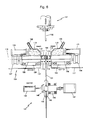
- Fig. 6 is a schematic view showing the structure of an apparatus for manufacturing cutting blades according to a preferred embodiment of the present invention. Although several parts and accessories used in general in the field related to the present invention are not illustrated in the drawings, it is understood that those parts and accessories can be incorporated into a part of the apparatus of the present invention.
- the manufacturing apparatus of the present invention comprises an upper punch assembly 101 having at least one punch 102, and a lower die assembly 104 having at least one forming pattern 103 which has a cross sectional shape corresponding to the upper punch 102 and in which a diamond-metal powder mixture is filled and formed into a predetermined shape.
- a steel core supporting device 141 is positioned to support a disk-shaped steel core 131 in place under the lower portion of the forming pattern and to stepwise rotate the steel core at a predetermined angle after one cutting segment is welded to the periphery of the steel core in the manufacturing process.
- means for supporting the entire lower die assembly and for adjusting the height of the lower die assembly when necessary is arranged under the left and right sides of the lower die assembly 104.
- the apparatus of the present invention as shown has only one of each of the upper punch 102 and the forming pattern 103, it is obvious to those skilled in the art of the present invention that the apparatus may have a plurality of each of the upper punch and the forming pattern Also, although not shown in the drawings, the upper punch assembly 101 is connected to a press so as to be vertically reciprocated thereby.
- the upper punch assembly 101 can be vertically reciprocating by the press connected to the upper portion thereof and, accordingly, the punch 102 can enters into and exits from the forming pattern 103.
- the lower die assembly 104 has a left die assembly 105 and a right die assembly 106. These left and right die assemblies 105, 106 are reciprocating in a horizontal direction for a predetermined distance by hydraulic cylinders 107, 108 connected to the respective external end. Such reciprocation is lineally effected in a horizontal direction by virtue of a linear motion guide 109 installed at the lower portion of the left and right die assemblies 105, 106. Left and right forming dies 111, 112 are detachably mounted insides of the left and right die assemblies 105, 106, respectively.
- a recess is formed on the respective inner surface of the left and right forming dies 111, 112 so as to form a forming pattern 103 when the forming dies move toward each other and contact fluid-tightly. Further explanation in this regard will be provided with reference to Figs. 7 and 8.
- the left and right forming dies 111, 112 are detachably mounted insides of the left and right die assemblies 105, 106, respectively, by conventional fastening means such as bolts 113.
- An electric coil 114 which is heating means for heating the diamond-metal powder mixture in the forming pattern 103 in the forming process, is arranged to penetrate the respective body of the left and right forming dies 111, 112.
- the electric coil 114 is a rectangular shaped coil of a hollow type made of copper, and cooling water is supplied into the hollow inside of the coil in the forming process. Both ends of the electric coil are connected to an AC power supply (not shown).
- the AC power supply is one easily available such as an inverter of high frequency, medium frequency or low frequency.
- one electric coil 114 has been arranged to surround one forming pattern 103, it is understood that, when the forming die has two or more forming patterns, a further electric coil of identical with or similar to the electric coil 114 may be arranged for each of the forming patterns.
- left and right cooling blocks 115, 116 are arranged beneath the left and right forming dies 111, 112.
- a flexible pipe 117 is connected to the respective cooling block to supply cooling water from a separate cooling water supply source (not shown). If necessary, any one of the left and right cooling blocks 115, 116 may be omitted.
- two cooling blocks have been arranged to be in contact with the left and right surfaces of one disk-shaped steel core, it is understood that, when two or more steel cores are placed under the forming die which has two or more forming patterns, further cooling blocks having a structure identical with or similar to the cooling blocks 115, 116 may be arranged between those steel cores
- the filling feeders 118, 119 are supplied with diamond particles, metal powder or a mixture thereof from a forming material supply source (not shown) through conduits 122, 123 thereof.
- the steel core supporting device 141 positioned below the lower die assembly 104 comprises left and right supporting blocks 142, 143, a hydraulic cylinder 144 for reciprocating the left supporting block 142 in a horizontal direction when supporting in place and removing the disk-shaped steel core 131, a supporting axis 146 inserted into the center hole of the steel core and rotationally supported by a bearing 145, and a stepping motor 147 for stepwise rotating the axis 146 at predetermined angle.
- one disk-shaped steel core is supported by the left and right supporting blocks 142, 143, it is understood that, when the forming die has two or more forming patterns, two or more steel cores placed under the forming die corresponding to the number of the forming patterns can be supported to have same intervals as the forming patterns by the supporting device, for example, which has the left and right supporting blocks and further intermediate supporting blocks or spacers sandwiched between the steel cores.
- Fig. 7 is a partially enlarged sectional view showing in detail the left and right forming dies 111, 112 and left and right cooling blocks 115, 116 mounted beneath the forming dies.
- the left and right forming dies 111, 112 are detachably mounted insides of the left and right die assemblies 105, 106, respectively, by conventional fastening means such as bolts 113.
- the left and right forming dies 111, 112 can be easily removed when repairing, or easily replaced with those of different size when forming cutting segments of different size depending on the kinds of cutting blade.
- a recess is formed on the respective inner surface of the left and right forming dies 111, 112 so as to form a forming pattern 103 when the forming dies move toward each other and contact fluid-tightly.
- An electric coil 114 for heating the diamond-metal powder mixture in the forming pattern 103 in the forming process is arranged to penetrate the respective body of the left and right forming dies 111, 112.
- Left and right cooling blocks 115, 116 are arranged beneath the left and right forming dies 111, 112, as described above, to which a flexible pipe 117 is connected to supply cooling water from a separate cooling water supply source.
- the cooling blocks 115, 116 are preferably made of copper having good heat conductivity, while other metal or alloy having superior heat conductivity may be used to make the cooling blocks.
- the inner surfaces of the cooling blocks 115, 116 are closely contacted with the outer surfaces of the disk-shaped steel core 131 so as to support the steel core in place and at the same time cool the heat of high temperature transmitted to the steel core from the forming pattern.
- the cooling blocks 115, 116 are mounted on the die assemblies by bolts 125, etc. so as to be easily detachable from the die assemblies when necessary to repair or replace them.
- Fig. 8 is a schematic top-plan view illustrating an example of arranging the electric coil for heating the cutting segments in the forming dies so as to perform the sintering and welding process.
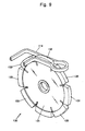
- Fig. 9 is a perspective view showing a relative arrangement between the electric coil illustrated on Fig. 8 and cutting segments of a cutting blade.
- the electric coil 114 is arranged to penetrate the bodies of the left and right forming dies 111, 112 so as to be positioned adjacently to the forming pattern 103 formed by the recesses 126, 127 of the left and right forming dies 111, 112.
- the penetrating paths of the electric coil in the forming dies are shown in dotted lines.
- the electric coil 114 is insulated from the left and right forming dies 111, 112 using any suitable insulating means (not shown) when penetratingly arranged in the forming dies.
- the electric coil 114 is arranged to surround the external surface of a cutting segment 132 being welded to the periphery of the disk-shaped steel core 131 of a cutting blade so as to inductively heat the metal powder of the diamond-metal powder mixture constituting the cutting segment 132.
- the bending portion of the coil surrounding the cutting segment 132 is protruded as a ring shape as shown in the drawings so as to prevent the coil from contacting with the cutting segment 133 already formed and welded to the periphery of the disk-shaped steel core 131 and positioned in front of the cutting segment 132 under forming process at present.
- the manufacturing apparatus according to the present invention is programmed so that the entire steps of manufacturing can be automatically performed, while semiautomatic or manual operation of the apparatus is also possible.
- a diamond-metal powder mixture is prepared by mixing diamond particles of a predetermined size and metal powder of a predetermined ingredient and size.
- the diamond-metal powder mixture is filled in a forming material supply source (not shown) and is supplied to the filling feeders 118, 119.
- the forming material i.e., the diamond-metal powder mixture
- supplied to the filling feeders 118, 119 is filled into the forming pattern 103 formed as a result of tight contact of the left and right forming dies 111, 112, by the filling feeders 118, 119 horizontally reciprocating by the hydraulic cylinders 120, 121.
- the disk-shaped steel core 131 Prior to filling the diamond-metal powder mixture into the forming pattern 103, the disk-shaped steel core 131 is placed under the forming dies 111, 112 and supported by the supporting device 141, so that a predetermined peripheral part of the steel core 131 can be positioned inside of the lower portion of the forming dies 111, 112.
- the upper punch assembly 101 descends and the punch 102 thereof enters into the forming pattern 103 so as to apply a pressure to the diamond-metal powder mixture in the forming pattern 103 and form the mixture into a cutting segment of a desired shape.
- an electric power is applied to the electric coil 114 arranged to penetrate the left and right forming dies 111, 112 so as to inductively heat the diamond-metal powder mixture in the forming pattern 103.
- the metal powder in the diamond-metal powder mixture is sintered at a high temperature and simultaneously the formed cutting segment is welded to the periphery of the disk-shaped steel core 131 placed in advance under the lower portion of the forming pattern.
- the diamond-metal powder mixture is heated at a high temperature, for example, about 600°C - 1200°C.
- a high temperature is undesirably transmitted to the electric coil 114 as well as to the disk-shaped steel core 131.
- cooling water flows inside of the electric coil 114 and the cooling blocks 115, 116, as described above .
- a stepping motor 147 of the supporting device 141 positioned below the die assembly and supporting the steel core 131 rotates at a predetermined angle, and consequently the steel core 131 rotates at a predetermined angle.
- a series of process for forming, sintering and welding the cutting segments to the next positions of the periphery of the steel core 131 is repeatedly performed in the order as described above, according to a programmed continuous operation sequence. As a result, a plurality of cutting segments is completely welded throughout the periphery of the disk-shaped steel core 131.
- Fig. 10 is a sectional view illustrating the structure of a cutting segment in a cutting blade as produced according to a preferred embodiment of the present invention, using a mixture of metal powder and diamond-metal powder granules.
- the diamond-metal powder granules have a regular size as described previously. Therefore, as shown in Fig. 10, the sintered diamond-metal powder granules 134 are uniformly distributed inside of the cutting segments 133 of the cutting blade 130 completed through a series of forming, sintering and welding steps.
- the metal powder in the mixture is wholly sintered and at the same time the metal powder surrounding the core diamond particles in the granules is sintered to a predetermined depth, since the diamond-metal powder granules are instantaneously heated at the temperature ranged 600°C -1200°C by the induction heating as described above. Thus, the diamond particles are rarely affected from the high temperature.
- the diamond-metal powder granules are formed by coating metal powder having a particle size ranged 0.5 ⁇ m - 200 ⁇ m around the core diamond particles having a particle size ranged 1 ⁇ m - 8000 ⁇ m. These diamond-metal powder granules have a Rockwell hardness of H R C 1 - 60 after sintered. As a result, a cutting segment manufactured by forming and sintering a mixture of metal powder and diamond-metal powder granules into a predetermined shape has a Rockwell hardness of H R C 1 - 60 in its entirety.
- the metal used for manufacturing the diamond-metal powder mixture or granules contains, for example, at least one of cobalt, iron or tungsten as a main ingredient, and additionally contains at least one of copper, tin, copper-tin alloy, nickel or titanium.
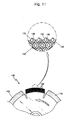
- Fig. 11 is a partially enlarged sectional view showing an abrasive state of the cutting segments in use, which have been made according to a preferred embodiment of the present invention. As shown, the heights of the diamond particles exposed from the abraded surfaces of the cutting segments 133 are almost regular after use of the cutting blade 130 for a long period of time.
- the sintered metal powder crusting a core diamond particle 135 has a high hardness and, since the diamond-metal powder granules have been integrally sintered, a binding force between the diamond particles and the sintered metal powder is superior. Accordingly, even if the diamond granules exposed from the surfaces of the cutting segments 133 rotating in an arrow direction are abraded in use, the residual powder layers 136 of the sintered metal powder in the granules, surrounding behind the core diamond particles 135, are maintained for a considerable period of time, thereby supporting the core diamond particles 135 for a considerable period of time. In fact, the core diamond particles 135 of the granules exposed from the cutting segments in the cutting process are almost maintained without falling off until the exposed size of the core diamond particles 135 reaches about 3/5.
- the present invention provides a method for manufacturing cutting blades within a short period of time and with low manufacturing cost, by drastically shortening the manufacturing process, since the steps of forming, sintering and welding of the cutting segments can be performed concurrently.
- the present invention also provides an apparatus for manufacturing cutting blades requiring relatively small space for installation and capable of economically manufacturing cutting blades with a simple manufacturing process, by using not separate and independent manufacturing facilities but a single manufacturing facility.
- the method and apparatus of the present invention enable the manufacture of a cutting blade having uniform distribution of diamond particles in the sintered diamond-metal powder mixture, and in which diamond particles exposed due to abrasion of the cutting segments after long time use are not easily fallen off from the cutting segments.
Landscapes
- Engineering & Computer Science (AREA)
- Mechanical Engineering (AREA)
- Manufacturing & Machinery (AREA)
- Chemical & Material Sciences (AREA)
- Composite Materials (AREA)
- Materials Engineering (AREA)
- Polishing Bodies And Polishing Tools (AREA)
- Powder Metallurgy (AREA)
- Processing Of Stones Or Stones Resemblance Materials (AREA)
Claims (14)
- Verfahren zur Herstellung von Schneidblättern mit jeweils einem scheibenförmigen Stahlkern mit einer bestimmten Dicke und einer Vielzahl von Schneidsegmenten, die aus einer Mischung von Diamantpartikeln und Metallpulver bestehen und am Umfang des Stahlkernes in gleichmässigen Intervallen fest angebracht sind, wobei das Verfahren die Schritte umfasst:Bereitstellung einer Diamant-Metallpulvermischung, indem Diamantpartikel mit einer bestimmten Grösse mit Metallpulver von bestimmter Ingredienz und Grösse vermischt werden;Abstützung des scheibenförmigen Stahlkerns unter dem unteren Teil eines Formwerkzeugs bestehend aus wenigstens einem vertikal auf- und abgehenden oberen Stempelteil und einer unteren Formungsanordnung mit wenigstens einem Formungsnest mit einer Querschnittsgestalt entsprechend dem oberen Stempelteil;Formen der Diamant-Metallpulvermischung zu Schneidsegmenten mit einer bestimmten Gestalt, indem eine bestimmte Menge der Mischung in das Formungsnest des Formwerkzeugs eingefüllt und die Mischung im Formungsmuster verpresst wird;Sintern des Metallpulvers in der Diamant-Metallpulvermischung der Schneidsegmente, indem die Mischung während ihrer Formung im Formungsnest erhitzt wird; undVerschweissen der Schneidsegmente durch die Erhitzung mit dem Umfang des scheibenförmigen Stahlkerns, der am unteren Teil des Formungsnestes der unteren Formungsanordnung plaziert ist.
- Verfahren nach Anspruch 1, beidem die Schritte der Formung der Diamant-Metallpulvermischung zu Schneidsegmenten durch Verpressen der in das Formungsnest des Formwerkzeugs eingefüllten Mischung, das Sintern des Metallpulvers in der Diamant-Metallpulvermischung der Schneidsegmente durch Erhitzung der Diamant-Metallpulvermischung und das Verschweissen der Schneidsegmente durch Erhitzen mit einem bestimmten Bereich am Umfang des scheibenförmigen Stahlkerns gleichzeitig vorgenommen werden.
- Verfahren nach Anspruch 1 oder 2, umfassend einen Schritt des Verschweissens einer Vielzahl von Schneidsegmenten in einer Reihenfolge längs des Umfanges des scheibenförmigen Stahlkerns, indem der Stahlkern um einen bestimmten Winkel schrittweise gedreht wird.
- Verfahren nach Anspruch 1 oder 2, bei dem die Erhitzung durch eine elektrische Erhitzung erfolgt.
- Verfahren nach Anspruch 4, bei dem die elektrische Erhitzung vorgenommen wird, indem eine Wechselspannung an eine Spule angelegt wird, die nahe der Aussenseite des Formungsnestes der unteren Formungsanordnung des Formwerkzeugs angeordnet ist.
- Verfahren nach Anspruch 4, bei dem die elektrische Erhitzung durch eine Gleichspannung vorgenommen wird, die an der Diamant-Metallpulvermischung im Formungsnest der unteren Formungsanordnung über den oberen Stempelteil des Formwerkzeugs angelegt wird, wenn das Verpressen und Formen der Mischung zu Schneidsegmenten erfolgt.
- Verfahren nach Anspruch 1, bei dem die Diamant-Metallpulvermischung aus Metallpulver von bestimmter Ingredienz und Grösse und Diamant-Metallpulverkörnern besteht, die durch Beschichtung mit Metallpulver einer bestimmten Ingredienz und Grösse um Diamantpartikel einer bestimmten Grösse gebildet sind.
- Vorrichtung zur Herstellung von Schneidblättern (130), wobei jedes einen scheibenförmigen Stahlkern (131) von bestimmter Dicke und eine Vielzahl von Schneidsegmenten (132) aufweist, die aus einer Mischung von Diamantpartikeln und Metallpulver gebildet und am Umfang des Schneidkerns (131) in regelmässigen Intervallen fest angebracht sind, weiche Vorrichtung aufweist:wenigstens einen vertikal auf- und abgehenden oberen Stempelteil (102);eine untere Formungsanordnung (104) mit wenigstens einem Formungsnest (103) mit einer Querschnittsgestalt, die dem oberen Stempelteil (102) entspricht, um die Mischung aus Diamantpartikeln und Metallpulver darin einzufüllen und die Mischung zu einer bestimmten Gestalt zu formen;eine Stützvorrichtung (141) zum Abstützen des scheibenförmigen Stahlkerns (131), bei dem ein bestimmter Umfang am unteren Bereich des Formungsnests (103) der unteren Formungsanordnung (104) positioniert ist; undeine Heizeinrichtung (114) zum Erhitzen der Diamant-Metallpulvermischung, die im Formungsnest (103) der unteren Formungsanordnung (104) eingefüllt ist;
- Vorrichtung nach Anspruch 8, weiter umfassend wenigstens einen Füllzufördere (118, 119) zum Einfüllen der Diamantpartikel, des Metallpulvers oder einer Mischung davon in das Formungsnest während der Hin- und Herbewegung in horizontaler Richtung auf der Oberseite der unteren Formungsanordnung (104).
- Vorrichtung nach Anspruch 8, bei dem die Heizeinrichtung eine elektrische Heizeinrichtung (114) ist.
- Vorrichtung nach Anspruch 8 oder 10, bei dem die Heizeinrichtung eine Induktionsheizspule (114) umfasst, die nahe der Aussenseite des Formungsnests (103) der unteren Formungsanordnung (104) angeordnet ist.
- Vorrichtung nach Anspruch 8 oder 10, bei dem die Heizeinrichtung eine Gleichstromenergiezufuhr ist, die an die Diamant-Metallpulvermischung im Formungsnest (103) der unteren Formungsanordnung (104) über den oberen Stempeltei (102) beim Verpressen und Formen der Mischung zu Schneidsegmenten (132) angelegt wird.
- Vorrichtung nach Anspruch 8, weiter umfassend wenigstens eine Kühl- oder Wärmesenkeinrichtung (115, 116), die unter dem unteren Bereich des Formungsnests (103) der unteren Formungsanordnung (104) angeordnet ist, so dass sie mit beiden oder entweder der linken oder rechten Flächen des scheibenförmigen Stahlkerns (131) in Berührung tritt, der unter dem unteren Bereich des Formungsnests (103) der unteren Formungsanordnung (104) plaziert ist.
- Vorrichtung nach Anspruch 8, bei dem die Stützvorrichtung (141) zum Abstützen des scheibenförmigen Stahlkerns (131) eine Dreheinrichtung (147) aufweist, um den Stahlkern (131) über einen bestimmten Winkel schrittweise zu drehen.
Applications Claiming Priority (2)
| Application Number | Priority Date | Filing Date | Title |
|---|---|---|---|
| KR2000067055 | 2000-11-13 | ||
| KR10-2000-0067055A KR100426843B1 (ko) | 2000-11-13 | 2000-11-13 | 절삭톱의 제조방법 및 장치와, 그에 의해 제조된 절삭톱 |
Publications (3)
| Publication Number | Publication Date |
|---|---|
| EP1205271A2 EP1205271A2 (de) | 2002-05-15 |
| EP1205271A3 EP1205271A3 (de) | 2005-06-15 |
| EP1205271B1 true EP1205271B1 (de) | 2007-11-14 |
Family
ID=19698559
Family Applications (1)
| Application Number | Title | Priority Date | Filing Date |
|---|---|---|---|
| EP00126793A Expired - Lifetime EP1205271B1 (de) | 2000-11-13 | 2000-12-06 | Verfahren und Vorrichtung zum Herstellen eines Schneideblattes |
Country Status (7)
| Country | Link |
|---|---|
| US (1) | US6562288B2 (de) |
| EP (1) | EP1205271B1 (de) |
| JP (2) | JP2002166323A (de) |
| KR (1) | KR100426843B1 (de) |
| AT (1) | ATE378128T1 (de) |
| DE (1) | DE60037121T2 (de) |
| ES (1) | ES2296593T3 (de) |
Families Citing this family (29)
| Publication number | Priority date | Publication date | Assignee | Title |
|---|---|---|---|---|
| US6633739B2 (en) * | 2001-12-17 | 2003-10-14 | Xerox Corporation | Detoning blade |
| US8105692B2 (en) * | 2003-02-07 | 2012-01-31 | Diamond Innovations Inc. | Process equipment wear surfaces of extended resistance and methods for their manufacture |
| US7238018B2 (en) * | 2004-05-10 | 2007-07-03 | The Japan Steel Works, Ltd. | Method and apparatus for heating plastic extruding die |
| KR100783867B1 (ko) * | 2005-12-08 | 2007-12-10 | 현대자동차주식회사 | 연료전지용 분리판 및 그 제조방법 |
| KR100689022B1 (ko) * | 2005-12-29 | 2007-03-02 | 이성목 | 핀을 이용한 다이아몬드 절삭 팁의 성형 장치 및 그 제조방법 |
| KR100699033B1 (ko) * | 2005-12-29 | 2007-03-23 | 이성목 | 다이아몬드 절삭 팁의 성형 장치 및 그 제조 방법 |
| KR100709393B1 (ko) * | 2006-02-10 | 2007-04-20 | 이화다이아몬드공업 주식회사 | 절삭/연마 공구용 세그먼트의 제조 방법 및 그 제조 장치 |
| KR100846932B1 (ko) * | 2006-09-21 | 2008-07-17 | 현대자동차주식회사 | 예비 성형체를 이용한 연료전지용 분리판의 2단계 제조방법 및 이를 이용해 제작된 분리판 |
| DE102007018791B3 (de) * | 2007-04-20 | 2008-08-14 | Atlas Diamant Werkzeuge Gmbh | Segmentband für eine Bohrkrone und Bohrkrone |
| SE532992C2 (sv) * | 2007-11-08 | 2010-06-08 | Alfa Laval Corp Ab | Förfarande för framställning av en diamantkomposit, grönkropp, diamantkomposit samt användning av diamantkompositen |
| US20100319513A1 (en) * | 2009-06-21 | 2010-12-23 | Yu-Chang Hsu | Combined splitting blade |
| DE102009053570B4 (de) * | 2009-10-19 | 2014-09-11 | Dr. Fritsch Sondermaschinen Gmbh | Kaltpresse und Verfahren zur Herstellung von Grünlingen |
| KR101071554B1 (ko) * | 2010-04-06 | 2011-10-10 | 주식회사 하스 | 세라믹 유치관 제조방법 및 이에 의해 제조된 세라믹 유치관 |
| CN101879634B (zh) * | 2010-06-21 | 2012-07-04 | 晶日金刚石工业有限公司 | 金刚石分齿烧结锯片成型装置 |
| US8778259B2 (en) * | 2011-05-25 | 2014-07-15 | Gerhard B. Beckmann | Self-renewing cutting surface, tool and method for making same using powder metallurgy and densification techniques |
| US8855982B2 (en) * | 2012-02-06 | 2014-10-07 | Sumitomo Heavy Industries, Ltd. | Analysis device and simulation method |
| CN102896374B (zh) * | 2012-10-11 | 2015-04-29 | 河北冀凯实业集团有限公司 | 一种金刚石锯片制作工艺 |
| KR101334983B1 (ko) * | 2013-08-09 | 2013-11-29 | 정은성 | 다이아몬드 절삭팁 성형용 금속분말 자동 충전장치 |
| CN106625301A (zh) * | 2016-11-21 | 2017-05-10 | 郑州狮虎磨料磨具有限公司 | 超硬磨料搅拌机 |
| CN107855731A (zh) * | 2017-09-29 | 2018-03-30 | 芜湖普威技研有限公司 | 电子油门安装支架生产焊接工艺 |
| CN108044532B (zh) * | 2017-12-25 | 2023-09-12 | 珠海大白鲨磨料磨具有限公司 | 一种砂轮液压成型工艺 |
| US12017280B2 (en) | 2018-12-21 | 2024-06-25 | Hilti Aktiengesellschaft | Method for producing a green body and method for further processing the green body into a machining segment for the dry machining of concrete materials |
| EP3670036A1 (de) * | 2018-12-21 | 2020-06-24 | Hilti Aktiengesellschaft | Verfahren zur herstellung eines bearbeitungssegmentes für die trockenbearbeitung von betonwerkstoffen |
| EP3670041A1 (de) | 2018-12-21 | 2020-06-24 | Hilti Aktiengesellschaft | Verfahren zur herstellung eines bearbeitungssegmentes für die trockenbearbeitung von betonwerkstoffen |
| CN111266654B (zh) * | 2019-12-17 | 2021-07-02 | 江苏陆氏金刚石工具有限公司 | 一种金刚石锯片的生产工艺 |
| SE2050932A1 (en) * | 2020-08-04 | 2022-02-05 | Husqvarna Ab | Improved cutting segments for abrasive cutting tools |
| JP7667053B2 (ja) * | 2021-09-30 | 2025-04-22 | 高周波熱錬株式会社 | 加工装置 |
| CN114406355B (zh) * | 2022-01-28 | 2022-12-02 | 江苏美特森切削工具有限公司 | 一种链条式组装锯条及制造方法、装置 |
| JP7202758B1 (ja) * | 2022-04-25 | 2023-01-12 | 株式会社谷テック | 金属切断用丸鋸のチップ製造方法およびこれを用いた金属切断用丸鋸の製造方法 |
Family Cites Families (10)
| Publication number | Priority date | Publication date | Assignee | Title |
|---|---|---|---|---|
| DE2323242C3 (de) * | 1973-05-09 | 1978-03-09 | Robert Bosch Gmbh, 7000 Stuttgart | Verfahren und Vorrichtung zur Herstellung einer verschleißfesten Hartmetalischicht auf einem Metallgegenstand |
| GB2081174A (en) * | 1980-08-02 | 1982-02-17 | Stevens John Anthony | Button Bit Grinding Tool Head |
| US4593776A (en) * | 1984-03-28 | 1986-06-10 | Smith International, Inc. | Rock bits having metallurgically bonded cutter inserts |
| US4630692A (en) * | 1984-07-23 | 1986-12-23 | Cdp, Ltd. | Consolidation of a drilling element from separate metallic components |
| SE455277B (sv) * | 1986-03-21 | 1988-07-04 | Uddeholm Tooling Ab | Sett att pulvermetallurgiskt framstella ett foremal genom varmpressning av pulver i en keramikform medelst ett partikulert tryckmedium |
| JPS63300871A (ja) * | 1987-05-30 | 1988-12-08 | Sanwa Daiyamondo Kogyo Kk | 超砥粒カッタ−の製造方法およびその製造装置 |
| KR910008246B1 (ko) * | 1989-11-25 | 1991-10-12 | 조경양 | 고속절단이 가능한 다이아몬드톱의 제조방법 |
| US5405573A (en) * | 1991-09-20 | 1995-04-11 | General Electric Company | Diamond pellets and saw blade segments made therewith |
| WO1997011803A1 (en) * | 1995-09-27 | 1997-04-03 | The Ishizuka Research Institute, Ltd. | Super-abrasive grain-containing composite material |
| US6063333A (en) * | 1996-10-15 | 2000-05-16 | Penn State Research Foundation | Method and apparatus for fabrication of cobalt alloy composite inserts |
-
2000
- 2000-11-13 KR KR10-2000-0067055A patent/KR100426843B1/ko not_active Expired - Fee Related
- 2000-12-06 ES ES00126793T patent/ES2296593T3/es not_active Expired - Lifetime
- 2000-12-06 AT AT00126793T patent/ATE378128T1/de not_active IP Right Cessation
- 2000-12-06 DE DE60037121T patent/DE60037121T2/de not_active Expired - Fee Related
- 2000-12-06 EP EP00126793A patent/EP1205271B1/de not_active Expired - Lifetime
- 2000-12-12 US US09/733,983 patent/US6562288B2/en not_active Expired - Fee Related
- 2000-12-15 JP JP2000381494A patent/JP2002166323A/ja active Pending
-
2003
- 2003-06-17 JP JP2003171988A patent/JP2004001220A/ja not_active Withdrawn
Also Published As
| Publication number | Publication date |
|---|---|
| KR20020037082A (ko) | 2002-05-18 |
| US6562288B2 (en) | 2003-05-13 |
| EP1205271A3 (de) | 2005-06-15 |
| DE60037121T2 (de) | 2008-09-11 |
| US20020057981A1 (en) | 2002-05-16 |
| EP1205271A2 (de) | 2002-05-15 |
| DE60037121D1 (de) | 2007-12-27 |
| ATE378128T1 (de) | 2007-11-15 |
| KR100426843B1 (ko) | 2004-04-13 |
| ES2296593T3 (es) | 2008-05-01 |
| JP2002166323A (ja) | 2002-06-11 |
| JP2004001220A (ja) | 2004-01-08 |
Similar Documents
| Publication | Publication Date | Title |
|---|---|---|
| EP1205271B1 (de) | Verfahren und Vorrichtung zum Herstellen eines Schneideblattes | |
| US7269986B2 (en) | Method of forming a tubular blank into a structural component and die therefor | |
| CN1284901A (zh) | 利用脉冲式磁力将平板制成碟的设备和方法 | |
| CN101704277B (zh) | 多层金刚石钎焊体的制造方法 | |
| KR20010093106A (ko) | 소결 아티클의 제조방법 및 그 방법으로 제조된 제품 | |
| EP2889095B1 (de) | Verfahren und Vorrichtung zur Herstellung von gesintertem Seltenerdmagneten | |
| AU2015371098A1 (en) | Method for manufacturing a continuous drill ring for a core drill bit | |
| CN101569903A (zh) | 实现金刚石在刀头中定向有序排布的方法 | |
| CN109079138B (zh) | 一种增材制造重复使用基板及重复使用方法 | |
| US20240139814A1 (en) | Removing the Support Structure by Means of a Laser Beam Integrated on a Robot Arm | |
| US3950149A (en) | Method for continuously producing resinoid wheels | |
| KR20210063820A (ko) | 복합단조용 예비성형장치 | |
| US20050167072A1 (en) | Apparatus and method for manufacturing metal mold using semisolid rapid tooling | |
| CN111331312B (zh) | 一种大型铸造件型芯局部缺陷修复方法 | |
| WO2004024359A2 (en) | Improved method of forming a tubular blank into a structural component and die therefor | |
| AU2015371033A1 (en) | Drill ring for a core drill bit and method for producing a drill ring | |
| CN113927753B (zh) | 一种箭头槽齿焊接锯片及其制备方法 | |
| CN102909536A (zh) | 一种生产硬质合金刀片的方法 | |
| EP2889096B1 (de) | Verfahren zur Herstellung eines gesinterten Seltenerdmagneten | |
| KR101153214B1 (ko) | 다이아몬드 연마공구의 제조방법 | |
| KR20210109285A (ko) | 신속하고 정확한 금형 제작을 위한 장치 및 방법 | |
| CN107262821B (zh) | 金刚石放射状定位分布全工作层超薄锯片的制作工艺 | |
| CN118023450B (zh) | 一种六面顶用活塞锻造工艺及其锻造工装 | |
| WO2008099347A1 (en) | Electro discharge sintering manufacturing | |
| CN109894674B (zh) | 带有钎焊硬质合金模块的锯片及其生产方法 |
Legal Events
| Date | Code | Title | Description |
|---|---|---|---|
| PUAI | Public reference made under article 153(3) epc to a published international application that has entered the european phase |
Free format text: ORIGINAL CODE: 0009012 |
|
| AK | Designated contracting states |
Kind code of ref document: A2 Designated state(s): AT BE CH CY DE DK ES FI FR GB GR IE IT LI LU MC NL PT SE TR |
|
| AX | Request for extension of the european patent |
Free format text: AL;LT;LV;MK;RO;SI |
|
| PUAL | Search report despatched |
Free format text: ORIGINAL CODE: 0009013 |
|
| AK | Designated contracting states |
Kind code of ref document: A3 Designated state(s): AT BE CH CY DE DK ES FI FR GB GR IE IT LI LU MC NL PT SE TR |
|
| AX | Request for extension of the european patent |
Extension state: AL LT LV MK RO SI |
|
| RIC1 | Information provided on ipc code assigned before grant |
Ipc: 7B 23P 15/28 B Ipc: 7B 23D 65/00 B Ipc: 7B 22F 7/08 A |
|
| 17P | Request for examination filed |
Effective date: 20051214 |
|
| AKX | Designation fees paid |
Designated state(s): AT BE CH CY DE DK ES FI FR GB GR IE IT LI LU MC NL PT SE TR |
|
| 17Q | First examination report despatched |
Effective date: 20060914 |
|
| GRAP | Despatch of communication of intention to grant a patent |
Free format text: ORIGINAL CODE: EPIDOSNIGR1 |
|
| RTI1 | Title (correction) |
Free format text: METHOD AND APPARATUS FOR MANUFACTURING CUTTING BLADES |
|
| GRAS | Grant fee paid |
Free format text: ORIGINAL CODE: EPIDOSNIGR3 |
|
| GRAA | (expected) grant |
Free format text: ORIGINAL CODE: 0009210 |
|
| AK | Designated contracting states |
Kind code of ref document: B1 Designated state(s): AT BE CH CY DE DK ES FI FR GB GR IE IT LI LU MC NL PT SE TR |
|
| REG | Reference to a national code |
Ref country code: GB Ref legal event code: FG4D |
|
| REG | Reference to a national code |
Ref country code: CH Ref legal event code: EP |
|
| REG | Reference to a national code |
Ref country code: IE Ref legal event code: FG4D |
|
| REF | Corresponds to: |
Ref document number: 60037121 Country of ref document: DE Date of ref document: 20071227 Kind code of ref document: P |
|
| PG25 | Lapsed in a contracting state [announced via postgrant information from national office to epo] |
Ref country code: NL Free format text: LAPSE BECAUSE OF FAILURE TO SUBMIT A TRANSLATION OF THE DESCRIPTION OR TO PAY THE FEE WITHIN THE PRESCRIBED TIME-LIMIT Effective date: 20071114 Ref country code: LI Free format text: LAPSE BECAUSE OF FAILURE TO SUBMIT A TRANSLATION OF THE DESCRIPTION OR TO PAY THE FEE WITHIN THE PRESCRIBED TIME-LIMIT Effective date: 20071114 Ref country code: SE Free format text: LAPSE BECAUSE OF FAILURE TO SUBMIT A TRANSLATION OF THE DESCRIPTION OR TO PAY THE FEE WITHIN THE PRESCRIBED TIME-LIMIT Effective date: 20080214 Ref country code: CH Free format text: LAPSE BECAUSE OF FAILURE TO SUBMIT A TRANSLATION OF THE DESCRIPTION OR TO PAY THE FEE WITHIN THE PRESCRIBED TIME-LIMIT Effective date: 20071114 |
|
| NLV1 | Nl: lapsed or annulled due to failure to fulfill the requirements of art. 29p and 29m of the patents act | ||
| REG | Reference to a national code |
Ref country code: ES Ref legal event code: FG2A Ref document number: 2296593 Country of ref document: ES Kind code of ref document: T3 |
|
| REG | Reference to a national code |
Ref country code: CH Ref legal event code: PL |
|
| PG25 | Lapsed in a contracting state [announced via postgrant information from national office to epo] |
Ref country code: AT Free format text: LAPSE BECAUSE OF FAILURE TO SUBMIT A TRANSLATION OF THE DESCRIPTION OR TO PAY THE FEE WITHIN THE PRESCRIBED TIME-LIMIT Effective date: 20071114 |
|
| PG25 | Lapsed in a contracting state [announced via postgrant information from national office to epo] |
Ref country code: MC Free format text: LAPSE BECAUSE OF NON-PAYMENT OF DUE FEES Effective date: 20071231 Ref country code: DK Free format text: LAPSE BECAUSE OF FAILURE TO SUBMIT A TRANSLATION OF THE DESCRIPTION OR TO PAY THE FEE WITHIN THE PRESCRIBED TIME-LIMIT Effective date: 20071114 |
|
| ET | Fr: translation filed | ||
| PG25 | Lapsed in a contracting state [announced via postgrant information from national office to epo] |
Ref country code: BE Free format text: LAPSE BECAUSE OF FAILURE TO SUBMIT A TRANSLATION OF THE DESCRIPTION OR TO PAY THE FEE WITHIN THE PRESCRIBED TIME-LIMIT Effective date: 20071114 |
|
| PLBE | No opposition filed within time limit |
Free format text: ORIGINAL CODE: 0009261 |
|
| STAA | Information on the status of an ep patent application or granted ep patent |
Free format text: STATUS: NO OPPOSITION FILED WITHIN TIME LIMIT |
|
| PG25 | Lapsed in a contracting state [announced via postgrant information from national office to epo] |
Ref country code: PT Free format text: LAPSE BECAUSE OF FAILURE TO SUBMIT A TRANSLATION OF THE DESCRIPTION OR TO PAY THE FEE WITHIN THE PRESCRIBED TIME-LIMIT Effective date: 20080414 |
|
| 26N | No opposition filed |
Effective date: 20080815 |
|
| PG25 | Lapsed in a contracting state [announced via postgrant information from national office to epo] |
Ref country code: IE Free format text: LAPSE BECAUSE OF NON-PAYMENT OF DUE FEES Effective date: 20071206 |
|
| PG25 | Lapsed in a contracting state [announced via postgrant information from national office to epo] |
Ref country code: GR Free format text: LAPSE BECAUSE OF FAILURE TO SUBMIT A TRANSLATION OF THE DESCRIPTION OR TO PAY THE FEE WITHIN THE PRESCRIBED TIME-LIMIT Effective date: 20080215 |
|
| PG25 | Lapsed in a contracting state [announced via postgrant information from national office to epo] |
Ref country code: FI Free format text: LAPSE BECAUSE OF FAILURE TO SUBMIT A TRANSLATION OF THE DESCRIPTION OR TO PAY THE FEE WITHIN THE PRESCRIBED TIME-LIMIT Effective date: 20071114 |
|
| PGFP | Annual fee paid to national office [announced via postgrant information from national office to epo] |
Ref country code: ES Payment date: 20081230 Year of fee payment: 9 |
|
| PGFP | Annual fee paid to national office [announced via postgrant information from national office to epo] |
Ref country code: DE Payment date: 20081230 Year of fee payment: 9 |
|
| PGFP | Annual fee paid to national office [announced via postgrant information from national office to epo] |
Ref country code: GB Payment date: 20081229 Year of fee payment: 9 |
|
| PG25 | Lapsed in a contracting state [announced via postgrant information from national office to epo] |
Ref country code: CY Free format text: LAPSE BECAUSE OF FAILURE TO SUBMIT A TRANSLATION OF THE DESCRIPTION OR TO PAY THE FEE WITHIN THE PRESCRIBED TIME-LIMIT Effective date: 20071114 |
|
| PG25 | Lapsed in a contracting state [announced via postgrant information from national office to epo] |
Ref country code: LU Free format text: LAPSE BECAUSE OF NON-PAYMENT OF DUE FEES Effective date: 20071206 |
|
| PGFP | Annual fee paid to national office [announced via postgrant information from national office to epo] |
Ref country code: IT Payment date: 20090123 Year of fee payment: 9 |
|
| PG25 | Lapsed in a contracting state [announced via postgrant information from national office to epo] |
Ref country code: TR Free format text: LAPSE BECAUSE OF FAILURE TO SUBMIT A TRANSLATION OF THE DESCRIPTION OR TO PAY THE FEE WITHIN THE PRESCRIBED TIME-LIMIT Effective date: 20071114 |
|
| PGFP | Annual fee paid to national office [announced via postgrant information from national office to epo] |
Ref country code: FR Payment date: 20081229 Year of fee payment: 9 |
|
| PG25 | Lapsed in a contracting state [announced via postgrant information from national office to epo] |
Ref country code: FR Free format text: LAPSE BECAUSE OF NON-PAYMENT OF DUE FEES Effective date: 20091231 |
|
| GBPC | Gb: european patent ceased through non-payment of renewal fee |
Effective date: 20091206 |
|
| PG25 | Lapsed in a contracting state [announced via postgrant information from national office to epo] |
Ref country code: DE Free format text: LAPSE BECAUSE OF NON-PAYMENT OF DUE FEES Effective date: 20100701 |
|
| PG25 | Lapsed in a contracting state [announced via postgrant information from national office to epo] |
Ref country code: GB Free format text: LAPSE BECAUSE OF NON-PAYMENT OF DUE FEES Effective date: 20091206 |
|
| PG25 | Lapsed in a contracting state [announced via postgrant information from national office to epo] |
Ref country code: IT Free format text: LAPSE BECAUSE OF NON-PAYMENT OF DUE FEES Effective date: 20091206 |
|
| REG | Reference to a national code |
Ref country code: ES Ref legal event code: FD2A Effective date: 20110406 |
|
| PG25 | Lapsed in a contracting state [announced via postgrant information from national office to epo] |
Ref country code: ES Free format text: LAPSE BECAUSE OF NON-PAYMENT OF DUE FEES Effective date: 20110324 |
|
| PG25 | Lapsed in a contracting state [announced via postgrant information from national office to epo] |
Ref country code: ES Free format text: LAPSE BECAUSE OF NON-PAYMENT OF DUE FEES Effective date: 20091207 |
|
| REG | Reference to a national code |
Ref country code: FR Ref legal event code: ST Effective date: 20110826 |