EP1205269A1 - Casting slab for shadow mask, method for heat treatment therof and material for shadow mask - Google Patents
Casting slab for shadow mask, method for heat treatment therof and material for shadow mask Download PDFInfo
- Publication number
- EP1205269A1 EP1205269A1 EP00931545A EP00931545A EP1205269A1 EP 1205269 A1 EP1205269 A1 EP 1205269A1 EP 00931545 A EP00931545 A EP 00931545A EP 00931545 A EP00931545 A EP 00931545A EP 1205269 A1 EP1205269 A1 EP 1205269A1
- Authority
- EP
- European Patent Office
- Prior art keywords
- slab
- casting
- shadow mask
- casting slab
- segregation
- Prior art date
- Legal status (The legal status is an assumption and is not a legal conclusion. Google has not performed a legal analysis and makes no representation as to the accuracy of the status listed.)
- Withdrawn
Links
Images



Classifications
-
- H—ELECTRICITY
- H01—ELECTRIC ELEMENTS
- H01J—ELECTRIC DISCHARGE TUBES OR DISCHARGE LAMPS
- H01J9/00—Apparatus or processes specially adapted for the manufacture, installation, removal, maintenance of electric discharge tubes, discharge lamps, or parts thereof; Recovery of material from discharge tubes or lamps
- H01J9/02—Manufacture of electrodes or electrode systems
- H01J9/14—Manufacture of electrodes or electrode systems of non-emitting electrodes
- H01J9/142—Manufacture of electrodes or electrode systems of non-emitting electrodes of shadow-masks for colour television tubes
-
- B—PERFORMING OPERATIONS; TRANSPORTING
- B22—CASTING; POWDER METALLURGY
- B22D—CASTING OF METALS; CASTING OF OTHER SUBSTANCES BY THE SAME PROCESSES OR DEVICES
- B22D11/00—Continuous casting of metals, i.e. casting in indefinite lengths
-
- B—PERFORMING OPERATIONS; TRANSPORTING
- B22—CASTING; POWDER METALLURGY
- B22D—CASTING OF METALS; CASTING OF OTHER SUBSTANCES BY THE SAME PROCESSES OR DEVICES
- B22D21/00—Casting non-ferrous metals or metallic compounds so far as their metallurgical properties are of importance for the casting procedure; Selection of compositions therefor
-
- C—CHEMISTRY; METALLURGY
- C21—METALLURGY OF IRON
- C21D—MODIFYING THE PHYSICAL STRUCTURE OF FERROUS METALS; GENERAL DEVICES FOR HEAT TREATMENT OF FERROUS OR NON-FERROUS METALS OR ALLOYS; MAKING METAL MALLEABLE, e.g. BY DECARBURISATION OR TEMPERING
- C21D6/00—Heat treatment of ferrous alloys
- C21D6/001—Heat treatment of ferrous alloys containing Ni
-
- C—CHEMISTRY; METALLURGY
- C21—METALLURGY OF IRON
- C21D—MODIFYING THE PHYSICAL STRUCTURE OF FERROUS METALS; GENERAL DEVICES FOR HEAT TREATMENT OF FERROUS OR NON-FERROUS METALS OR ALLOYS; MAKING METAL MALLEABLE, e.g. BY DECARBURISATION OR TEMPERING
- C21D8/00—Modifying the physical properties of ferrous metals or ferrous alloys by deformation combined with, or followed by, heat treatment
-
- C—CHEMISTRY; METALLURGY
- C22—METALLURGY; FERROUS OR NON-FERROUS ALLOYS; TREATMENT OF ALLOYS OR NON-FERROUS METALS
- C22C—ALLOYS
- C22C30/00—Alloys containing less than 50% by weight of each constituent
-
- C—CHEMISTRY; METALLURGY
- C22—METALLURGY; FERROUS OR NON-FERROUS ALLOYS; TREATMENT OF ALLOYS OR NON-FERROUS METALS
- C22C—ALLOYS
- C22C38/00—Ferrous alloys, e.g. steel alloys
- C22C38/08—Ferrous alloys, e.g. steel alloys containing nickel
-
- H—ELECTRICITY
- H01—ELECTRIC ELEMENTS
- H01J—ELECTRIC DISCHARGE TUBES OR DISCHARGE LAMPS
- H01J2229/00—Details of cathode ray tubes or electron beam tubes
- H01J2229/07—Shadow masks
- H01J2229/0727—Aperture plate
- H01J2229/0733—Aperture plate characterised by the material
Definitions
- the present invention relates to a casting slab for shadow mask made of Ni-Fe based alloy which exhibits an excellent streak suppression effect at the time of etching, the heat treatment method thereof and material for shadow mask, and more particularly to a casting slab for shadow mask made of Ni-Fe based alloy which is suitably used as a shadow mask of a color-television cathode ray tube or a computer-display cathode ray tube, the heat treatment method thereof and material for shadow mask.
- a Ni-Fe alloy (particularly, a Fe-36%Ni alloy) which is known as an Invar alloy and is used as shadow mask material of a large-sized color-television cathode ray tube or a high-definition cathode ray tube for computer display suffers from a drawback that a stripe pattern called "streaks" appears in the direction parallel to the rolling direction when the perforation by etching is performed.
- the segregation of Ni-Fe which is present in a material sheet served for etching is considered to be a main cause of the generation of the streaks.
- This segregation is a phenomenon that the solidification segregation which is generated at the time of performing the continuous casting or the ordinary ingot casting with respect to material still remains in a final product sheet even after passing through steps which is a combination of hot working, cold working, annealing and the like after performed by the above-mentioned casting.
- the segregation at the time of solidification is generated in the state that it is extended in the rolling direction of the coil at the preliminary step and hence, when the product sheet is etched, they become apparent as etching irregularities in stripes parallel to the rolling direction.
- Japanese Patent No. 2130577 Japanese Patent Publication 78270/1995 discloses a method which suppresses the generation of streaks by applying the heat treatment above a fixed temperature and a fixed time with respect to a continuous casting slab whose solidification structure is controlled.
- Japanese Patent No. 2000062 Japanese Patent Publication 78270/1995 discloses a method which applies annealing to the casting slab at a high temperature for a long time in the same manner.
- Japanese Patent No. 1950743 Japanese Patent Publication 68128/1994 discloses a method which suppresses the generation of streaks by performing heat treatment of the slab at a high temperature for a long time exceeding conditions which satisfy the relationship between a fixed temperature and a fixed time irrespective of the difference between the continuous casting and the ordinary ingot casting.
- the basic principle of these prior art mainly aims at the prevention of etching irregularities which are present in the inside of the slab due to the heat treatment at a high temperature for a long time by homogenizing the segregation of Ni, C, Si, Mn, Cr and the like by making use of the thermal diffusion.
- Japanese Patent no. 2130577 Publication also refers to the solidification structure, what this reference implies resides in the prevention of the influence which the crystalline orientation of the solidification structure affects the crystalline orientation in a product sheet and etching irregularities derived from such crystalline orientation.
- a first aspect of a casting slab for shadow mask of the present invention is directed to a casting slab for preparing a shadow mask which comprises an Ni-Fe alloy containing 30 to 45% of Ni, wherein the casting slab has a cast structure comprising a columnar crystal and/or a chill crystal in an amount of 99% or more and exhibits the excellent quality with respect to streaks.
- a second aspect of the casting slab of the present invention resides in that the casting slab does not contain equiaxed crystal.
- a third aspect of the casting slab of the present invention resides in that the casting slab is obtained by using a continuous casting method in which casting operation is carried out with no electromagnetic stirring and with maintaining a melt temperature of the non-solidificated part in the slab to a temperature equal to or above the liquidus thereof.
- a heat treatment method of a casting slab for shadow mask of the present invention is characterized in that the above-mentioned casting slab is subjected to a heat treatment at a given temperature and for a given time such that the K value becomes 150 ⁇ m or more.
- Shadow mask material of the present invention is characterized in that the material is manufactured through steps including hot rolling, cold rolling and annealing using the above-mentioned casting slab.
- Fig. 1 is a graph showing K values when the soaking condition of a casting slab is changed.
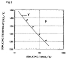
- Fig. 2 is a graph showing K values when the soaking condition of a casting slab is changed.
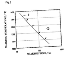
- Fig. 3 is a graph showing K values when the soaking condition of a casting slab is changed.
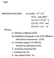
- Fig. 4 shows a relation equation to obtain the diffusion distance K value.
- Fig. 5 is a graph showing the relationship between the standard deviation of Ni segregation in slab and the soaking condition of the casting slab.
- Fig. 6 is a graph showing the relationship between the standard deviation of Ni segregation in a slab and the rank of streaks.
- Fig. 7 is a graph showing the relationship between the K value and the rank of streaks.
- Fig. 8 is a graph showing the result of measurement of the Ni segregation in the casting slab of the present invention and in the casting slab of a comparison example.
- Fig. 9 is a photograph showing the structure of the casting slab of the present invention.
- Fig. 10 is a photograph showing the structure of the casting slab of the comparison example.
- the structure of the casting slab containing this Ni segregation comprises a columnar crystal and/or a chill crystal.
- the material which becomes the subject of the present invention is material for shadow mask comprised of Ni-Fe alloy containing 30 to 45 % of Ni. In most cases, material called "Invar alloy" which contains 36 % of Ni and whose balance is substantially made of Fe is used.
- the composition of the present invention may contain, for example, constituents such as Nb, Co, Cr or the like which substantially amounts to few % at maximum when necessary. However, these constituents do not influence the effect of the present invention and hence, the present invention includes the material containing these constituents.
- the slab for shadow mask of the present invention is restricted to a continuous casting slab which comprises a columnar crystal and/or a chill crystal in an amount of 99 % or more, and preferably 100 % due to a reason set forth below. That is, in the slab solidification step, when the segregation is reduced due to a thermal diffusion in the preliminary step, the most decisive factor is the interval of the fluctuation of components of the segregation. Based on the general finding that the shorter this interval, the heating temperature necessary for the reduction of the segregation can be lowered or the heating time can be shortened, the relationship between the segregation and the solidification structure of the slab has been focused and has been subjected to the detailed investigation.
- the interval between the segregation is extremely short compared with other solidification structure. Further, it was also found that the interval of the segregation in these solidification structures depends on the interval of the primary dendrite arms. Since the segregation derived from the secondary and cubic dendrite arms is dissipated by the heat treatment performed in a relatively short time, they are not taken into consideration specifically in the present invention.
- the structure of the slab for shadow mask comprises the columnar crystal structure and/or the chill crystal structure in an amount of 99 % or more, and preferably 100 %.
- the chill crystal structure since the formation of the structure is limited to a quenching solidification portion which comes into contact with a mold at the time of solidification, the structure is hardly formed and merely amounts to few % of the total volume of an ordinary continuous casting slab.
- the casting is performed while stirring the molten steel with an electromagnetic stirring (EMS) to avoid the concentration of the segregation and the generation of the nests at the central portion of the slab.
- EMS electromagnetic stirring
- the central portion of the slab does not form the columnar crystal structure but forms the equiaxed crystal structure and hence, the method is not preferable.
- it is necessary to perform the operation which intentionally stops the EMS so as to suppress the flow of the molten steel in the inside of the continuous casting mold as much as possible.
- a method which stops the EMS and further suppresses the flow of the molten steel using an electromagnetic brake or the like is also effective.
- the temperature of the molten steel in the non-solidified portion in the slab becomes equal to or below the liquidus thereof, the nucleus of the equiaxed crystal is generated and grown in the molten steel and hence, the targeted columnar crystal structure cannot be obtained. Accordingly, it is preferable to perform the operation in the state that the temperature of the molten steel is maintained above the liquidus in the phase diagram. To be more specific, it is preferable to maintain the degree of separation ( ⁇ T) from the liquidus to more than 25 °C.
- the upper limit of ⁇ T differs within the range of operation conditions of the individual continuous casting machine and hence, it is unnecessary to specifically define the upper limit in the present invention.
- the upper limit of the heating temperature of the slab is not specifically determined, it is preferable to set the upper limit to a temperature which is 10 degrees below a melting point of the material.
- the relationship equation shown in Fig. 4 is a known relationship equation which indicates the diffusion distance that the segregation generated in the slab can be diffused in the slab by the heat treatment of the casting slab performed after the generation of the segregation.
- Fig. 7 is a view which shows the relationship between the K values shown in Table 1 and the rank of streaks. It can be understood as follows from Fig. 7. That is, it is preferable to perform the heat treatment under the condition that the K value becomes equal to or more than 150 ⁇ m to obtain the rank C of streaks. It is preferable to perform the heat treatment under the condition that the K value becomes equal to or more than 160 ⁇ m to obtain the rank B of streaks. It is preferable to perform the heat treatment under the condition that the K value becomes equal to or more than 170 ⁇ m to obtain the rank C of streaks.
- the rank of streaks means the degree of the streaks which practically brings about no problem when the material is actually formed into a shadow mask at an etching maker of shadow masks.
- the rank A indicates a case in which the streaks are not observed at all
- the rank E indicates a case in which the streaks are extremely strongly observed
- the rank difference between the rank A and the rank E is divided into 5 stages. It has been found that, as the degree of the streaks, the rank C or more is preferable from the experience and the achievement of conventional materials. Accordingly, it is preferable to produce the shadow mask material of equal to or above the rank C.
- inventors of the present invention have investigated the relationship between the streaks and the Ni segregation in the slab.
- Fig. 6 is a graph showing the relationship between the standard deviation of the Ni segregation of the slab and the rank of streaks.
- the result shown in Fig. 6 is obtained such that shadow mask materials are produced from materials which differ in the standard deviation of the Ni segregation of the slab by simulating steps up to the plate thickness of the shadow mask material product, the shadow mask materials are etched and the rank of streaks (the strength of streaks) which appear on the etching surface at the time of etching are investigated.
- Fig. 5 is a graph which shows the result of the method. That is, although it is understood from Fig. 5 that when the heat treatment is performed at a high temperature for a long time, the tendency to reduce the Ni segregation is observed, it is also understood from Fig. 5 that it is desirable to set the K value to equal to or more than 150 ⁇ m to set the standard deviation of Ni segregation of slab to equal to or less than 0.07 mass %.
- Fig. 5 also shows the value that the standard deviation of the Ni segregation of slab takes at a portion of the slab which is located in the vicinity of the center of the slab where the diffusion of the segregation hardly progresses due to the longest interval of Ni segregation after soaking when the slab soaking is performed on the condition that the casting slab shows the K value on the axis of abscissas.
- "in the vicinity of the center of the slab” means a position which is approximately 3 mm displaced from the center of the slab in the thickness direction and the sampling was performed at this position.
- Fig. 1 to Fig. 3 show that corresponding to the shifting of the soaking condition from X ⁇ Y ⁇ Z, the diffusion of Ni progresses. That is, to enhance the diffusion of the Ni by performing the heat treatment of the cast slab, it is preferable to perform the heat treatment under the conditions with respect to the time and the temperature of the heat treatment which fall in an area O exceeding an X boundary line of Fig. 1. By performing the heat treatment under the conditions with respect to the time and the temperature of the heat treatment which fall in an area P exceeding a Y boundary line of Fig. 2, the diffusion of Ni can be further enhanced. Further, by performing the heat treatment under the conditions with respect to the time and temperature of the heat treatment which fall in an area Q exceeding a Z boundary line of Fig. 3, the diffusion of Ni can be still further enhanced.
- the areas which are respectively indicated by O in Fig. 1, P in Fig. 2 and Q in Fig. 3 show boundary lines which define areas where the K value of the diffusion distance indicated by the relationship equation (1) of Fig. 4 respectively becomes equal to or above 150 ⁇ m (corresponding to the O area in Fig. 1), preferably equal to or above 160 ⁇ m (corresponding to the P area in Fig. 2) and more preferably equal to or above 170 ⁇ m (corresponding to the Q area in Fig. 3).
- Ni segregation used for the evaluation of the material characteristics in the steps of the present invention are all measured and are subjected to the data processing under following conditions.
- Measuring apparatus X-ray microanalyzer JXA-8600MX produced by Nihon Denshi Ltd.
- Measuring method ray analysis
- Ni segregation measuring conditions were set as follows. Prove diameter 100 - 3000 nm Irradiation current 5.0 ⁇ 10 -7 A Acceleration voltage 20 kV Measuring time 0.5 sec/point Measuring length 10 mm Measuring interval 2 ⁇ m Spectral crystal LiF
- the shadow mask material is etched by immersing the shadow mask material in a ferric chloride solution of 5 degree of Baume at a room temperature for 20 minutes and the degree of the occurrence of the streaks is expressed by the ranking based on the observation of an etched surface with naked eyes.
- Fig. 8 shows the result of the measurement of the Ni segregation after performing the heat treatment of a portion of the slab in the vicinity of the center thereof at 1300 °C for 72 hours with respect to the continuous casting slab which comprises the columnar crystal and/or chill crystal in an amount of 99 % or more which is the requisite of the present invention and the continuous casting slab which is prepared as a comparison example and forms approximately 30 % of equiaxed crystal at the central portion of the slab.
- the measured distance by the ray analysis of the X-ray microanalyzer is taken on the axis of abscissas and the Ni by weight percent is taken on the axis of coordinates.
- the period of the Ni segregation in the continuous casting slab comprising the equiaxed crystal is 1000 m - 2000 m and hence is 2 - 4 times longer than that of the continuous casting slab comprising the columnar crystal so that the progress of the reduction of the segregation due to the heat treatment is difficult to achieve.
- This slab with the equiaxed crystal rate of 30 % was subjected to an experimental rolling to produce a thin film sample and the sample was etched. The result of the judgement of streaks was the rank E. Accordingly, it is not appropriate to use the casting slab having the equiaxed crystal structure as the shadow mask material.
- Fig. 9 shows the structure photograph of the casting slab of the present invention.
- Fig. 10 shows the structure photograph of the casting slab prepared as a comparison example.
- the etching condition in these photographs is that the ferric chloride solution (45 Baume/50°C) was sprayed for etching for one minute.
- the rate of the casting structure is expressed as the rate of area as viewed on a cross section perpendicular to the casting direction.
- the slab heat treatment condition for obtaining a given K value is selected from Table 1 in view of the ability and the productivity of a heat treatment furnace so that a product sheet having an arbitrary quality of streaks at the time of etching can be produced.
- the casting slab is formed into a hot rolled steel plate having a thickness of 2.5 mm and thereafter the steel plate is subjected to nitric acid pickling. It is preferable that the succeeding cold rolling is performed with the working rate in the range of approximately 20 - 95 %, the annealing is performed at a temperature which falls in the range of 700 - 1000 °C when a continuous furnace is used, and the refining rolling is performed with the working rate set in a range of 1 - 50 %. Thorough these steps, the shadowmaskmaterials having different sheet thickness within the range of 0.1 - 0.39 mm were produced. These shadow mask materials were etched and the qualities of streaks was checked. The result shows that the qualities of streaks fall in the areas of the ranks A, B, C shown in Fig. 7.
- the shadow mask materials which use the casting slab for shadow mask of the present invention can exhibit the level of the streaks at a degree which satisfies the conventional requirement of etching makers. Accordingly, it is possible to produce the materials having the quality of streaks which may be varied in compliance with the required quality up to a level served for ultra-definition shadow mask which is completely free from the occurrence of streaks after etching.
Landscapes
- Chemical & Material Sciences (AREA)
- Engineering & Computer Science (AREA)
- Mechanical Engineering (AREA)
- Materials Engineering (AREA)
- Metallurgy (AREA)
- Organic Chemistry (AREA)
- Crystallography & Structural Chemistry (AREA)
- Thermal Sciences (AREA)
- Physics & Mathematics (AREA)
- Manufacturing & Machinery (AREA)
- Continuous Casting (AREA)
- Electrodes For Cathode-Ray Tubes (AREA)
- Heat Treatment Of Steel (AREA)
- Investigating And Analyzing Materials By Characteristic Methods (AREA)
- Metal Rolling (AREA)
Abstract
Description
| K values when the soaking condition is changed. | ||||
| temperature | | |||
| 36 hr | 48 hr | 60 hr | 72 hr | |
| 1280 °C | 93 | 108 | 121 | 132 |
| 1300 °C | 107 | 124 | 138 | 152 |
| 1320 °C | 123 | 142 | 158 | 173 |
| 1340 ° | 140 | 161 | 180 | 198 |
Measuring apparatus: X-ray microanalyzer JXA-8600MX produced by Nihon Denshi Ltd.
Measuring method: ray analysis
| Prove diameter | 100 - 3000 nm |
| Irradiation current | 5.0 × 10⁻⁷ A |
| Acceleration voltage | 20 kV |
| Measuring time | 0.5 sec/ |
| Measuring length | |
| 10 mm | |
| Measuring interval | 2 µm |
| Spectral crystal | LiF |
Claims (5)
- A casting slab for producing a shadow mask comprising a Ni-Fe alloy containing 30 - 45 % of Ni, wherein the casting slab comprises a columnar crystal and/or a chill crystal in an amount of 99 % or more of the casting structure thus exhibiting the excellent quality with respect to streaks.
- A casting slab according to claim 1, wherein the casting slab contains no equiaxed crystal.
- A casting slab according to claim 1 or 2, wherein the casting slab is obtained using a continuous casting method which performs the operation without an electromagnetic stirring while maintaining the melting temperature of an non-solidificated portion in the slab equal to or above a liquidus.
- A heat treatment method of a casting slab for shadow mask characterized in that the heat treatment is performed at a given temperature and for a given time which can set the K value to equal to or more than 150 µm using the casting slab according to any one of claims 1 - 3.
- A material for shadow mask produced through steps including hot rolling, cold rolling and annealing using the casting slab of any one of preceding claims 1 - 4.
Applications Claiming Priority (5)
| Application Number | Priority Date | Filing Date | Title |
|---|---|---|---|
| JP14886699 | 1999-05-27 | ||
| JP14886699 | 1999-05-27 | ||
| JP37571999 | 1999-12-28 | ||
| JP37571999 | 1999-12-28 | ||
| PCT/JP2000/003323 WO2000072995A1 (en) | 1999-05-27 | 2000-05-24 | Casting slab for shadow mask, method for heat treatment therof and material for shadow mask |
Publications (2)
| Publication Number | Publication Date |
|---|---|
| EP1205269A1 true EP1205269A1 (en) | 2002-05-15 |
| EP1205269A4 EP1205269A4 (en) | 2004-12-22 |
Family
ID=26478927
Family Applications (1)
| Application Number | Title | Priority Date | Filing Date |
|---|---|---|---|
| EP00931545A Withdrawn EP1205269A4 (en) | 1999-05-27 | 2000-05-24 | FOUNDRY PLATE FOR SHADOW MASK, ITS HEAT TREATMENT METHOD AND MATERIAL USED FOR THE SHADOW MASK |
Country Status (7)
| Country | Link |
|---|---|
| US (1) | US6632298B1 (en) |
| EP (1) | EP1205269A4 (en) |
| JP (1) | JP4261777B2 (en) |
| KR (1) | KR100530898B1 (en) |
| CN (1) | CN1177662C (en) |
| AU (1) | AU4948500A (en) |
| WO (1) | WO2000072995A1 (en) |
Cited By (1)
| Publication number | Priority date | Publication date | Assignee | Title |
|---|---|---|---|---|
| WO2018160211A1 (en) * | 2017-02-28 | 2018-09-07 | Terrapower, Llc | Method for homogenizing steel compositions |
Families Citing this family (3)
| Publication number | Priority date | Publication date | Assignee | Title |
|---|---|---|---|---|
| JP4240823B2 (en) | 2000-09-29 | 2009-03-18 | 日本冶金工業株式会社 | Method for producing Fe-Ni permalloy alloy |
| KR101499943B1 (en) * | 2013-11-04 | 2015-03-06 | 동국제강주식회사 | Methode of forcasting for casting structure on the cast specimen of low carbon steel |
| JP6188643B2 (en) * | 2014-06-30 | 2017-08-30 | 新報国製鉄株式会社 | Extremely low thermal expansion alloy and manufacturing method thereof |
Family Cites Families (8)
| Publication number | Priority date | Publication date | Assignee | Title |
|---|---|---|---|---|
| CA1319589C (en) * | 1988-08-19 | 1993-06-29 | Masaomi Tsuda | Method of producing fe-ni series alloys having improved effect for restraining streaks during etching |
| JPH0711034B2 (en) * | 1988-12-23 | 1995-02-08 | 新日本製鐵株式会社 | Method for producing Fe-Ni alloy plate for shadow mask |
| JPH05222451A (en) * | 1992-02-14 | 1993-08-31 | Hitachi Metals Ltd | Production of ni-fe alloy |
| JP3222527B2 (en) * | 1992-02-26 | 2001-10-29 | 三菱レイヨン株式会社 | COMPOSITE YARN, FABRIC USING THE SAME, AND PROCESS FOR PRODUCING THEM |
| JP2937707B2 (en) * | 1993-10-04 | 1999-08-23 | 新日本製鐵株式会社 | Steel continuous casting method |
| JP3080301B2 (en) * | 1997-04-22 | 2000-08-28 | 日立金属株式会社 | Fe-Ni alloy thin plate with excellent surface properties and etching properties |
| JPH1180839A (en) * | 1997-09-08 | 1999-03-26 | Nkk Corp | Method for producing low thermal expansion alloy sheet for electronic parts excellent in streak unevenness suppression effect |
| JP2000096190A (en) * | 1998-09-21 | 2000-04-04 | Nisshin Steel Co Ltd | Stock for shadow mask, free from striped irregularity at etching, and its manufacture |
-
2000
- 2000-05-24 KR KR10-2001-7013923A patent/KR100530898B1/en not_active Expired - Fee Related
- 2000-05-24 AU AU49485/00A patent/AU4948500A/en not_active Abandoned
- 2000-05-24 EP EP00931545A patent/EP1205269A4/en not_active Withdrawn
- 2000-05-24 US US09/979,780 patent/US6632298B1/en not_active Expired - Fee Related
- 2000-05-24 JP JP2000621095A patent/JP4261777B2/en not_active Expired - Fee Related
- 2000-05-24 WO PCT/JP2000/003323 patent/WO2000072995A1/en not_active Ceased
- 2000-05-24 CN CNB008079994A patent/CN1177662C/en not_active Expired - Fee Related
Cited By (4)
| Publication number | Priority date | Publication date | Assignee | Title |
|---|---|---|---|---|
| WO2018160211A1 (en) * | 2017-02-28 | 2018-09-07 | Terrapower, Llc | Method for homogenizing steel compositions |
| CN110268076A (en) * | 2017-02-28 | 2019-09-20 | 泰拉能源公司 | Method for homogenizing steel compositions |
| US10738367B2 (en) | 2017-02-28 | 2020-08-11 | Terrapower, Llc | Method for homogenizing steel compositions |
| AU2017401534B2 (en) * | 2017-02-28 | 2023-05-18 | Terrapower, Llc | Method for homogenizing steel compositions |
Also Published As
| Publication number | Publication date |
|---|---|
| CN1351527A (en) | 2002-05-29 |
| JP4261777B2 (en) | 2009-04-30 |
| KR20020013860A (en) | 2002-02-21 |
| WO2000072995A1 (en) | 2000-12-07 |
| US6632298B1 (en) | 2003-10-14 |
| EP1205269A4 (en) | 2004-12-22 |
| AU4948500A (en) | 2000-12-18 |
| CN1177662C (en) | 2004-12-01 |
| KR100530898B1 (en) | 2005-11-23 |
Similar Documents
| Publication | Publication Date | Title |
|---|---|---|
| US10519534B2 (en) | Iron-based amorphous alloy thin strip | |
| US5252151A (en) | Fe-Ni alloy sheet for shadow mask having a low silicon segregation and method for manufacturing same | |
| US6632298B1 (en) | Casting slab for shadow mask, method for heat treatment thereof and material for shadow mask | |
| JP3335616B2 (en) | Powder for continuous casting for B-containing steel and method for producing B-containing steel | |
| JPH04103743A (en) | Fe-Ni alloy thin plate for shadow mask and its manufacturing method | |
| JPH0762217B2 (en) | Fe-Ni alloy thin plate for shadow mask and method for manufacturing the same | |
| JP3584209B2 (en) | Slab for shadow mask material, method for manufacturing the slab, and method for manufacturing shadow mask material excellent in streak quality and surface quality | |
| JPWO2000072995A1 (en) | Cast slab for shadow mask, heat treatment method therefor, and material for shadow mask | |
| JPH03281756A (en) | Fe-ni alloy sheet for shadow mask and its manufacture | |
| JPH04103744A (en) | Fe-ni alloy thin sheet for shadow mask and its manufacture | |
| JP3509643B2 (en) | Low thermal expansion alloy steel slab excellent in etchability after thinning and method for producing the same | |
| JP3615300B2 (en) | Method for producing shadow mask material without uneven stripes | |
| JP3623620B2 (en) | Etching property evaluation method for shadow mask material and shadow mask material that does not cause streak unevenness after etching | |
| JP2001181741A (en) | Method for producing low thermal expansion alloy thin sheet excellent in etching property, thin sheet for shadow mask and shadow mask | |
| KR102034448B1 (en) | Steel and method for the same | |
| JPH09316604A (en) | Iron-nickel base alloy shadow mask stock in which generation of stripe defect is suppressed | |
| JP3157239B2 (en) | Shadow mask material | |
| JP2000096190A (en) | Stock for shadow mask, free from striped irregularity at etching, and its manufacture | |
| JP3781836B2 (en) | Shadow mask material that does not cause uneven stripes during etching | |
| JP2001234247A (en) | Producing method for low thermal expansion alloy thin sheet excellent in etching property, thin sheet for shadow mask and shadow mask | |
| JP3356092B2 (en) | Continuous casting method | |
| JPH0762495A (en) | Alloy thin plate for electronic equipment with excellent etching processability | |
| JPH10280034A (en) | Heat treatment method for Fe-based amorphous alloy ribbon | |
| JP2001164320A (en) | Method for producing low thermal expansion alloy thin sheet excellent in etching property, thin sheet for shadow mask and shadow mask | |
| JP2559914B2 (en) | Method for producing Fe-Cu alloy plate excellent in homogeneity |
Legal Events
| Date | Code | Title | Description |
|---|---|---|---|
| PUAI | Public reference made under article 153(3) epc to a published international application that has entered the european phase |
Free format text: ORIGINAL CODE: 0009012 |
|
| 17P | Request for examination filed |
Effective date: 20011227 |
|
| AK | Designated contracting states |
Kind code of ref document: A1 Designated state(s): AT BE CH CY DE DK ES FI FR GB GR IE IT LI LU MC NL PT SE |
|
| AX | Request for extension of the european patent |
Free format text: AL;LT;LV;MK;RO;SI |
|
| RBV | Designated contracting states (corrected) |
Designated state(s): DE FR |
|
| A4 | Supplementary search report drawn up and despatched |
Effective date: 20041110 |
|
| RIC1 | Information provided on ipc code assigned before grant |
Ipc: 7B 22D 21/00 B Ipc: 7H 01J 9/14 B Ipc: 7C 22C 38/40 B Ipc: 7H 01J 29/07 B Ipc: 7C 22C 38/08 B Ipc: 7B 22D 11/00 A |
|
| 17Q | First examination report despatched |
Effective date: 20090218 |
|
| STAA | Information on the status of an ep patent application or granted ep patent |
Free format text: STATUS: THE APPLICATION IS DEEMED TO BE WITHDRAWN |
|
| 18D | Application deemed to be withdrawn |
Effective date: 20091104 |