EP1204545B1 - Airbag-vorrichtung - Google Patents
Airbag-vorrichtung Download PDFInfo
- Publication number
- EP1204545B1 EP1204545B1 EP00920533A EP00920533A EP1204545B1 EP 1204545 B1 EP1204545 B1 EP 1204545B1 EP 00920533 A EP00920533 A EP 00920533A EP 00920533 A EP00920533 A EP 00920533A EP 1204545 B1 EP1204545 B1 EP 1204545B1
- Authority
- EP
- European Patent Office
- Prior art keywords
- airbag
- vehicle
- airbag device
- housing
- cross
- Prior art date
- Legal status (The legal status is an assumption and is not a legal conclusion. Google has not performed a legal analysis and makes no representation as to the accuracy of the status listed.)
- Expired - Lifetime
Links
- 210000000746 body region Anatomy 0.000 claims description 3
- 238000004519 manufacturing process Methods 0.000 abstract description 2
- 230000002787 reinforcement Effects 0.000 description 4
- 238000007373 indentation Methods 0.000 description 3
- 238000010276 construction Methods 0.000 description 2
- 241001074085 Scophthalmus aquosus Species 0.000 description 1
- 230000004308 accommodation Effects 0.000 description 1
- 230000004913 activation Effects 0.000 description 1
- 239000003351 stiffener Substances 0.000 description 1
Images
Classifications
-
- B—PERFORMING OPERATIONS; TRANSPORTING
- B60—VEHICLES IN GENERAL
- B60R—VEHICLES, VEHICLE FITTINGS, OR VEHICLE PARTS, NOT OTHERWISE PROVIDED FOR
- B60R21/00—Arrangements or fittings on vehicles for protecting or preventing injuries to occupants or pedestrians in case of accidents or other traffic risks
- B60R21/02—Occupant safety arrangements or fittings, e.g. crash pads
- B60R21/16—Inflatable occupant restraints or confinements designed to inflate upon impact or impending impact, e.g. air bags
- B60R21/20—Arrangements for storing inflatable members in their non-use or deflated condition; Arrangement or mounting of air bag modules or components
- B60R21/213—Arrangements for storing inflatable members in their non-use or deflated condition; Arrangement or mounting of air bag modules or components in vehicle roof frames or pillars
Definitions
- the present invention relates to an airbag device with an airbag housing for Inclusion of an activatable, folded in the non-activated state Airbags that are curved along a transverse to the longitudinal direction of a vehicle Body area is arranged.
- An airbag device of the type mentioned is, for example, by DE-OS 197 26 782 A1 became known.
- the known airbag device has an airbag housing with an elongated shape and a rectangular cross section.
- the airbag housing is between one Inner sheet in the roof side and a front pillar and a panel arranged.
- care must be taken when installing the airbag device be that the outlet opening formed in the airbag housing for an activated Airbag is aligned accordingly to provide optimal impact protection for the To ensure vehicle occupants.
- due to the rectangular cross-sectional shape Difficulty in space-saving accommodation the airbag device between an interior lining of the vehicle body and the body components. As a compromise, changes to the Body components (indentations or features on the pillar, etc.) made, which can lead to a reduction in the strength of the column and again through additional body changes (reinforcements or stiffeners) must be balanced.
- An airbag device described in DE-OS 197 52 989 A1 also has Airbag housing with a rectangular cross-sectional shape, so that at Using this airbag housing problems analogous to the aforementioned airbag device result.
- the present invention is therefore based on the object of an airbag device to develop with an airbag housing that better meets the needs of the Body construction is adjusted without the operation of the airbag device too affect.
- an airbag device with an airbag housing to accommodate an activatable, in the non-activated state folded airbags solved that along a transverse to the longitudinal direction of a Vehicle curved body region is arranged and one transverse to Seen in the longitudinal direction of the vehicle, to the curvature of the body area has adapted cross-sectional shape.
- the cross-sectional shape can be “banana-shaped” or similar his.
- Such airbag housings can adapt well to those caused by the vehicle body Adjust the specified contour so that the airbag housing is space-saving can be made without having to make changes to the vehicle body.
- the creation of voids in the vehicle body can be omitted.
- the most Airbag housing-designed outlet opening for the airbag can be selected that this exits between the vehicle body and vehicle occupant and this optimally protects.
- the airbag device is used as head impact protection provided by the vehicle occupant.
- the airbag housing is on the Cross-sectional geometry of the so-called C-pillar of the vehicle body and / or the Adjusted inner contour of the vehicle roof.
- the cross-sectional geometry of the airbag housing proves itself in this vehicle area as particularly advantageous because it is particularly important there to weaken the C-pillar to avoid and a compensating reinforcement of an indentation C-pillar is only possible to a limited extent.
- the outlet opening for an outlet of the activated airbag from the airbag housing can be aligned in another airbag device such that the exit of the activated airbags takes place parallel to the window surface. This helps the Vehicle occupants in a vehicle accident as well as possible before a hard impact Vehicle body parts is protected.
- the airbag device is also used as side impact protection for the vehicle occupant Can be used when the airbag housing matches the cross-sectional geometry of the vehicle door is adjusted.
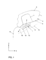
- the figure shows an airbag device in cross section.
- the section through parts of a vehicle body and through an airbag device 1 was carried out transversely to the longitudinal direction of the vehicle body.
- Arrow 2 denotes the direction to the top of the vehicle and arrow 3 denotes the direction to Vehicle interior.
- a pillar 4 of the vehicle body is composed of a outer side part 5 and an inner side part 6 together.
- the Strength of the column 4 increased by a reinforcement 7.
- a surface 8 of the column 4 is curved and by one in the figure only indicated cover 9 covered, so that these body parts are not directly are visible.
- the airbag housing 10 has a curved cross-sectional shape that the curvature of the surface 8 of the side part 6 is simulated.
Landscapes
- Engineering & Computer Science (AREA)
- Mechanical Engineering (AREA)
- Air Bags (AREA)
- Massaging Devices (AREA)
- Supplying Of Containers To The Packaging Station (AREA)
Description
- 1
- Airbag-Vorrichtung
- 2
- Richtung zur Fahrzeugoberseite
- 3
- Richtung zum Fahrzeuginnenraum
- 4
- Säule
- 5
- Äußeres Seitenteil
- 6
- Inneres Seitenteil
- 7
- Verstärkung
- 8
- Fläche
- 9
- Verkleidung
- 10
- Airbag-Gehäuse
- 11
- Airbag
- 12
- Austrittsöffnung
- 13
- Austrittsrichtung
- 14
- Fensterscheibe
Claims (5)
- Airbag-Vorrichtung (1) mit einem Airbag-Gehäuse (10) zur Aufnahme eines aktivierbaren, im nicht aktivierten Zustand zusammengefalteten Airbags (11), das entlang eines quer zur Längsrichtung eines Fahrzeugs gekrümmten Karosseriebereichs angeordnet ist, dadurch gekennzeichnet, daß das Airbag-Gehäuse (10) eine quer zur Längsrichtung des Fahrzeugs gesehene, an die Krümmung des Karosseriebereichs angepaßte Querschnittsform aufweist.
- Airbag-Vorrichtung nach Anspruch 1, dadurch gekennzeichnet, daß die Querschnittsform "bananenförmig" ausgebildet ist.
- Airbag-Vorrichtung nach Anspruch 1 oder 2, dadurch gekennzeichnet, daß die Airbag-Vorrichtung (1) als Kopfaufprallschutz des Fahrzeuginsassen vorgesehen ist, und daß das Airbag-Gehäuse (10) an die Querschnittsgeometrie der sog. C-Säule (4) der Fahrzeugkarosserie und/oder die Innenkontur des Fahrzeugdachs angepaßt ist.
- Airbag-Vorrichtung nach Anspruch 3, dadurch gekennzeichnet, daß die Austrittsöffnung (12) für einen Austritt des aktivierten Airbags (11) aus dem Airbag-Gehäuse (10) derart ausgerichtet ist, daß der Austritt des aktivierten Airbags (11) parallel zur Fensterfläche erfolgt.
- Airbag-Vorrichtung nach Anspruch 1 oder 2, dadurch gekennzeichnet, daß die Airbag-Vorrichtung als Seitenaufprallschutz des Fahrzeuginsassen vorgesehen ist, und daß das Airbag-Gehäuse an die Querschnittsgeometrie der Fahrzeugtür angepaßt ist.
Applications Claiming Priority (3)
| Application Number | Priority Date | Filing Date | Title |
|---|---|---|---|
| DE19919666A DE19919666A1 (de) | 1999-04-29 | 1999-04-29 | Airbag-Vorrichtung |
| DE19919666 | 1999-04-29 | ||
| PCT/EP2000/002522 WO2000066401A1 (de) | 1999-04-29 | 2000-03-22 | Airbag-vorrichtung |
Publications (2)
| Publication Number | Publication Date |
|---|---|
| EP1204545A1 EP1204545A1 (de) | 2002-05-15 |
| EP1204545B1 true EP1204545B1 (de) | 2004-10-20 |
Family
ID=7906393
Family Applications (1)
| Application Number | Title | Priority Date | Filing Date |
|---|---|---|---|
| EP00920533A Expired - Lifetime EP1204545B1 (de) | 1999-04-29 | 2000-03-22 | Airbag-vorrichtung |
Country Status (4)
| Country | Link |
|---|---|
| EP (1) | EP1204545B1 (de) |
| AT (1) | ATE280061T1 (de) |
| DE (2) | DE19919666A1 (de) |
| WO (1) | WO2000066401A1 (de) |
Family Cites Families (7)
| Publication number | Priority date | Publication date | Assignee | Title |
|---|---|---|---|---|
| US5772238A (en) * | 1995-12-12 | 1998-06-30 | Automotive Technologies International Inc. | Efficient airbag module |
| GB2293355B (en) * | 1994-09-08 | 1997-12-17 | Alliedsignal Deutschland Gmbh | Inflatable safety restraint for vehicle occupant protection |
| DE19642964A1 (de) * | 1996-10-18 | 1998-04-23 | Happich Gmbh Gebr | Airbagvorrichtung |
| SE508095C2 (sv) * | 1996-12-04 | 1998-08-24 | Volvo Ab | Anordning för skydd av åkande i ett fordon |
| DE19704051C2 (de) * | 1997-02-04 | 2001-10-18 | Mst Automotive Gmbh | Airbageinrichtung |
| DE19732069C2 (de) * | 1997-07-25 | 2001-02-15 | Daimler Chrysler Ag | Airbagmodul |
| DE19841347A1 (de) * | 1998-09-10 | 2000-03-16 | Volkswagen Ag | Airbagsystem für ein Kraftfahrzeug |
-
1999
- 1999-04-29 DE DE19919666A patent/DE19919666A1/de not_active Withdrawn
-
2000
- 2000-03-22 EP EP00920533A patent/EP1204545B1/de not_active Expired - Lifetime
- 2000-03-22 WO PCT/EP2000/002522 patent/WO2000066401A1/de not_active Ceased
- 2000-03-22 DE DE50008345T patent/DE50008345D1/de not_active Expired - Lifetime
- 2000-03-22 AT AT00920533T patent/ATE280061T1/de not_active IP Right Cessation
Also Published As
| Publication number | Publication date |
|---|---|
| ATE280061T1 (de) | 2004-11-15 |
| EP1204545A1 (de) | 2002-05-15 |
| DE19919666A1 (de) | 2000-11-02 |
| DE50008345D1 (de) | 2004-11-25 |
| WO2000066401A1 (de) | 2000-11-09 |
Similar Documents
| Publication | Publication Date | Title |
|---|---|---|
| DE60031115T2 (de) | Aufblasbarer airbag für ein kraftfahrzeug | |
| DE19632222B4 (de) | Innenverkleidung für ein Fahrzeugdach | |
| EP1364840A1 (de) | Fahrer-oder Beifahrerairbag | |
| EP0714818A1 (de) | Seitenaufprall-Gassack | |
| DE102005010024B4 (de) | Fahrzeugtürverkleidung und Verfahren zu deren Herstellung | |
| WO2008155261A1 (de) | Gassackanordnung für fahrzeuginsassen-rückhaltesystem | |
| DE10063473B4 (de) | Dachholm-Verkleidung für aufblasbares Rückhaltesystem | |
| EP1896299B1 (de) | Gassackanordnung für ein airbagmodul eines kraftfahrzeugs | |
| DE19930157B4 (de) | Luftsack für ein Kraftfahrzeug | |
| EP1607279A1 (de) | Schutzvorrichtung für den Fahrer eines Kraftfahrzeugs | |
| DE4223237A1 (de) | Gaskissen-System | |
| EP1412232B1 (de) | Insassenrückhaltesystem im fondbereich eines kraftfahrzeugs | |
| EP1607275A2 (de) | Fahrerseitige Insassen-Rückhalteeinrichtung | |
| DE19946013B4 (de) | Seitengerippe für eine selbsttragende Karosserie eines Kraftfahrzeuges | |
| EP2176096B1 (de) | Airbagmodul für ein kraftfahrzeug | |
| EP2495138B1 (de) | Airbaggehäuse mit integrierter Generatorstruktur | |
| DE10050689B4 (de) | Struktur zur Absorption von Aufprallenergie | |
| DE10359751A1 (de) | Instrumententafel mit einem Beifahrerairbag | |
| DE102010016749A1 (de) | Airbaggehäuse eines Airbagsystems und Airbagsystem | |
| DE19919666A1 (de) | Airbag-Vorrichtung | |
| DE10147608B4 (de) | Inneres Seitenwandteil einer Kraftfahrzeugkarosserie und Verfahren zur Herstellung desselben | |
| DE19955023A1 (de) | Vorichtung mit Airbag in einem Kraftfahrzeug | |
| DE19732069C2 (de) | Airbagmodul | |
| DE19510418A1 (de) | Sicherheitslenkrad | |
| DE29601497U1 (de) | Gassack-Seitenaufprall-Schutzeinrichtung |
Legal Events
| Date | Code | Title | Description |
|---|---|---|---|
| PUAI | Public reference made under article 153(3) epc to a published international application that has entered the european phase |
Free format text: ORIGINAL CODE: 0009012 |
|
| 17P | Request for examination filed |
Effective date: 20011129 |
|
| AK | Designated contracting states |
Kind code of ref document: A1 Designated state(s): AT BE CH CY DE DK ES FI FR GB GR IE IT LI LU MC NL PT SE |
|
| GRAP | Despatch of communication of intention to grant a patent |
Free format text: ORIGINAL CODE: EPIDOSNIGR1 |
|
| GRAS | Grant fee paid |
Free format text: ORIGINAL CODE: EPIDOSNIGR3 |
|
| GRAA | (expected) grant |
Free format text: ORIGINAL CODE: 0009210 |
|
| AK | Designated contracting states |
Kind code of ref document: B1 Designated state(s): AT BE CH CY DE DK ES FI FR GB GR IE IT LI LU MC NL PT SE |
|
| PG25 | Lapsed in a contracting state [announced via postgrant information from national office to epo] |
Ref country code: NL Free format text: LAPSE BECAUSE OF FAILURE TO SUBMIT A TRANSLATION OF THE DESCRIPTION OR TO PAY THE FEE WITHIN THE PRESCRIBED TIME-LIMIT Effective date: 20041020 Ref country code: IT Free format text: LAPSE BECAUSE OF FAILURE TO SUBMIT A TRANSLATION OF THE DESCRIPTION OR TO PAY THE FEE WITHIN THE PRESCRIBED TIME-LIMIT;WARNING: LAPSES OF ITALIAN PATENTS WITH EFFECTIVE DATE BEFORE 2007 MAY HAVE OCCURRED AT ANY TIME BEFORE 2007. THE CORRECT EFFECTIVE DATE MAY BE DIFFERENT FROM THE ONE RECORDED. Effective date: 20041020 Ref country code: FI Free format text: LAPSE BECAUSE OF FAILURE TO SUBMIT A TRANSLATION OF THE DESCRIPTION OR TO PAY THE FEE WITHIN THE PRESCRIBED TIME-LIMIT Effective date: 20041020 Ref country code: IE Free format text: LAPSE BECAUSE OF FAILURE TO SUBMIT A TRANSLATION OF THE DESCRIPTION OR TO PAY THE FEE WITHIN THE PRESCRIBED TIME-LIMIT Effective date: 20041020 |
|
| REG | Reference to a national code |
Ref country code: GB Ref legal event code: FG4D Free format text: NOT ENGLISH |
|
| REG | Reference to a national code |
Ref country code: CH Ref legal event code: EP |
|
| REG | Reference to a national code |
Ref country code: IE Ref legal event code: FG4D Free format text: GERMAN |
|
| REF | Corresponds to: |
Ref document number: 50008345 Country of ref document: DE Date of ref document: 20041125 Kind code of ref document: P |
|
| PG25 | Lapsed in a contracting state [announced via postgrant information from national office to epo] |
Ref country code: SE Free format text: LAPSE BECAUSE OF FAILURE TO SUBMIT A TRANSLATION OF THE DESCRIPTION OR TO PAY THE FEE WITHIN THE PRESCRIBED TIME-LIMIT Effective date: 20050120 Ref country code: GR Free format text: LAPSE BECAUSE OF FAILURE TO SUBMIT A TRANSLATION OF THE DESCRIPTION OR TO PAY THE FEE WITHIN THE PRESCRIBED TIME-LIMIT Effective date: 20050120 Ref country code: DK Free format text: LAPSE BECAUSE OF FAILURE TO SUBMIT A TRANSLATION OF THE DESCRIPTION OR TO PAY THE FEE WITHIN THE PRESCRIBED TIME-LIMIT Effective date: 20050120 |
|
| PG25 | Lapsed in a contracting state [announced via postgrant information from national office to epo] |
Ref country code: ES Free format text: LAPSE BECAUSE OF FAILURE TO SUBMIT A TRANSLATION OF THE DESCRIPTION OR TO PAY THE FEE WITHIN THE PRESCRIBED TIME-LIMIT Effective date: 20050131 |
|
| GBT | Gb: translation of ep patent filed (gb section 77(6)(a)/1977) |
Effective date: 20050211 |
|
| PG25 | Lapsed in a contracting state [announced via postgrant information from national office to epo] |
Ref country code: CY Free format text: LAPSE BECAUSE OF FAILURE TO SUBMIT A TRANSLATION OF THE DESCRIPTION OR TO PAY THE FEE WITHIN THE PRESCRIBED TIME-LIMIT Effective date: 20050322 Ref country code: LU Free format text: LAPSE BECAUSE OF NON-PAYMENT OF DUE FEES Effective date: 20050322 Ref country code: AT Free format text: LAPSE BECAUSE OF NON-PAYMENT OF DUE FEES Effective date: 20050322 |
|
| PG25 | Lapsed in a contracting state [announced via postgrant information from national office to epo] |
Ref country code: MC Free format text: LAPSE BECAUSE OF NON-PAYMENT OF DUE FEES Effective date: 20050331 Ref country code: LI Free format text: LAPSE BECAUSE OF NON-PAYMENT OF DUE FEES Effective date: 20050331 Ref country code: BE Free format text: LAPSE BECAUSE OF NON-PAYMENT OF DUE FEES Effective date: 20050331 Ref country code: CH Free format text: LAPSE BECAUSE OF NON-PAYMENT OF DUE FEES Effective date: 20050331 |
|
| NLV1 | Nl: lapsed or annulled due to failure to fulfill the requirements of art. 29p and 29m of the patents act | ||
| REG | Reference to a national code |
Ref country code: IE Ref legal event code: FD4D |
|
| PLBE | No opposition filed within time limit |
Free format text: ORIGINAL CODE: 0009261 |
|
| STAA | Information on the status of an ep patent application or granted ep patent |
Free format text: STATUS: NO OPPOSITION FILED WITHIN TIME LIMIT |
|
| ET | Fr: translation filed | ||
| BERE | Be: lapsed |
Owner name: VOLKSWAGEN A.G. Effective date: 20050331 |
|
| 26N | No opposition filed |
Effective date: 20050721 |
|
| REG | Reference to a national code |
Ref country code: CH Ref legal event code: PL |
|
| BERE | Be: lapsed |
Owner name: *VOLKSWAGEN A.G. Effective date: 20050331 |
|
| PG25 | Lapsed in a contracting state [announced via postgrant information from national office to epo] |
Ref country code: PT Free format text: LAPSE BECAUSE OF NON-PAYMENT OF DUE FEES Effective date: 20050320 |
|
| PGFP | Annual fee paid to national office [announced via postgrant information from national office to epo] |
Ref country code: GB Payment date: 20090223 Year of fee payment: 10 |
|
| PGFP | Annual fee paid to national office [announced via postgrant information from national office to epo] |
Ref country code: FR Payment date: 20090306 Year of fee payment: 10 |
|
| GBPC | Gb: european patent ceased through non-payment of renewal fee |
Effective date: 20100322 |
|
| REG | Reference to a national code |
Ref country code: FR Ref legal event code: ST Effective date: 20101130 |
|
| PG25 | Lapsed in a contracting state [announced via postgrant information from national office to epo] |
Ref country code: FR Free format text: LAPSE BECAUSE OF NON-PAYMENT OF DUE FEES Effective date: 20100331 |
|
| PG25 | Lapsed in a contracting state [announced via postgrant information from national office to epo] |
Ref country code: GB Free format text: LAPSE BECAUSE OF NON-PAYMENT OF DUE FEES Effective date: 20100322 |
|
| PGFP | Annual fee paid to national office [announced via postgrant information from national office to epo] |
Ref country code: DE Payment date: 20160331 Year of fee payment: 17 |
|
| REG | Reference to a national code |
Ref country code: DE Ref legal event code: R119 Ref document number: 50008345 Country of ref document: DE |
|
| PG25 | Lapsed in a contracting state [announced via postgrant information from national office to epo] |
Ref country code: DE Free format text: LAPSE BECAUSE OF NON-PAYMENT OF DUE FEES Effective date: 20171003 |