EP1203736B1 - Fördermodul zur gleichzeitigen übersetzen und drehen von Gegenständen - Google Patents
Fördermodul zur gleichzeitigen übersetzen und drehen von Gegenständen Download PDFInfo
- Publication number
- EP1203736B1 EP1203736B1 EP01307047A EP01307047A EP1203736B1 EP 1203736 B1 EP1203736 B1 EP 1203736B1 EP 01307047 A EP01307047 A EP 01307047A EP 01307047 A EP01307047 A EP 01307047A EP 1203736 B1 EP1203736 B1 EP 1203736B1
- Authority
- EP
- European Patent Office
- Prior art keywords
- segment
- support plate
- conveyor module
- chain
- cam track
- Prior art date
- Legal status (The legal status is an assumption and is not a legal conclusion. Google has not performed a legal analysis and makes no representation as to the accuracy of the status listed.)
- Expired - Lifetime
Links
Images


Classifications
-
- B—PERFORMING OPERATIONS; TRANSPORTING
- B65—CONVEYING; PACKING; STORING; HANDLING THIN OR FILAMENTARY MATERIAL
- B65G—TRANSPORT OR STORAGE DEVICES, e.g. CONVEYORS FOR LOADING OR TIPPING, SHOP CONVEYOR SYSTEMS OR PNEUMATIC TUBE CONVEYORS
- B65G47/00—Article or material-handling devices associated with conveyors; Methods employing such devices
- B65G47/22—Devices influencing the relative position or the attitude of articles during transit by conveyors
- B65G47/24—Devices influencing the relative position or the attitude of articles during transit by conveyors orientating the articles
- B65G47/244—Devices influencing the relative position or the attitude of articles during transit by conveyors orientating the articles by turning them about an axis substantially perpendicular to the conveying plane
Definitions
- This invention relates generally to a conveyor system for use in a carton forming and sealing machine, and more particularly to a conveyor module capable of rotating the carton by 90° while translating it from a first sealing station to a second sealing station.
- a flat blank of cardboard or paper board is first driven by a ram through a die to create a rectangular box configuration, the box having a bottom surface integrally joined to opposed side walls and end walls and a lid that is hinged along a top edge of one of the side walls.
- first tab comprising a folded extension of the lid beyond a mating side wall is adhesively bonded to that side wall.
- second and third tabs comprising extensions of the two side edges of the lid beyond the mating end walls of the box are adhesively bonded to the end walls of the box.
- a first overhead endless chain sweep conveyor or a conveyor having suitably spaced lugs on a conveyor chain may be used to translate the partially completed carton with the product therein past a hot glue gun at the first gluing station where a bead of glue is applied to the side wall surface to which the first extension tab of the lid is to be affixed.
- the sweep conveyor then urges the carton past a plow member which forces the first tab on the lid against the glue surface for a length of time sufficient to cause the glue to harden.
- the carton Before the second and third tabs comprising the extension of the two side edges of the lid can be glued to the mating end walls of the carton, the carton must first be rotated 90° so that the end walls will then be oriented parallel to the direction of travel of the conveyor, allowing a pair of glue guns to apply beads of glue to the opposite end walls as they move past the glue guns. Again, plow members downstream of the glue guns are used to urge the second and third extension tabs against their respective end walls of the box as the carton is carried forward by a downstream sweep conveyor.
- CH 394014 describes a conveyor system for rotating ceramic bricks as they pass through a dryer.
- the bricks rest on a pair of drive belts and, at a predetermined position on the conveyor, they are lifted from the belts by a carrier plate and rotated on the plate before being set down again on the belts.
- the carrier plate rotates by virtue of a laterally offset pin / roller assembly which collides, at a predetermined position, with a rail which is oblique to the direction of travel of the carrier plate.
- a 'snap mechanism' under the carrier plate ensures that the carrier plate has only two stable rotational positions, 90 degrees apart from one another.
- the conveyor module constructed in accordance with the present invention is operative to rotate products while in transit there along.
- the conveyor module comprises a frame having first and second sprocket wheels journaled for rotation on the frame about first and second, horizontal, parallel, spaced-apart axes, respectively.
- An endless chain spans the first and second sprocket wheels to define upper and lower chain flights.
- a generally rectangular carton support plate having upper and lower major surfaces is affixed to a first shaft at the center point of the lower major surface.
- the support plate further includes a cam follower on a second shaft that is affixed to the lower major surface and which is laterally offset from the first shaft along a midline of the rectangular support plate to the endless chain.
- the first shaft is secured by a coupler member so as to permit the support plate and first shaft to rotate about a longitudinal axis of the first shaft.
- the frame also supports a cam track where the cam track includes a first segment that is parallel to the upper chain flight over a first predetermined distance and which converges toward and intersects with the upper chain flight in a direction of travel of the upper chain flight.
- the aforementioned cam follower is adapted to engage the cam track to impart rotation of the support plate with the first shaft as the cam follower traverses the cam track.
- An additional cam track is supported on the frame and it includes a first segment that diverges away from the lower chain flight at a predetermined angle and is joined to a second segment that extends parallel to the lower chain flight in the direction of travel of the lower chain flight. Means are disposed adjacent the first segment of the additional cam track for causing the cam follower to traverse the first segment of the additional cam track to cause a return rotation of the support plate.
- the first shaft may be tubular and the support plate may include a cavity in fluid communication with the lumen of the tubular shaft.
- reference numeral 10 identifies a first, upstream gluing station in which partially formed cartons, such as of the type indicated generally by numeral 12 in Figure 2, are received from an infeed conveyor (not shown).
- the carton is seen to comprise a folded paper board or cardboard box-like structure comprising a bottom wall 14 with mutually perpendicular side walls 16 and 18 and mutually perpendicular end walls 20 and 22.
- a lid 24 is hinged to the side wall 18 along fold line 26 and it includes a first tab portion 28 formed by folding the lid 24 along fold line 30.
- Each of the side edges of the lid 24 has a foldable extension tab that is to be glued to end walls 20 and 22.
- the lid 24 has an extension tab 32 at its left end, when viewed in Figure 2, and an extension tab 34 at its right end. Extension tab 32 is adapted to be folded inward against the end wall 22 and, similarly, the extension tab 34 is adapted to be folded inward against the box end wall 20.
- a carton like that shown in Figure 2, is being moved in the direction of arrow 40 by an overhead sweep conveyor (not shown).
- a hot glue gun nozzle 42 As it moves past a hot glue gun nozzle 42, a bead of glue is deposited on the side wall 16 and as the carton moves rightward, the extension tab 28 is made to engage a plow member 44 which causes the tab 28 to be folded and pressed against the bead of glue earlier deposited by the glue gun 42.
- the carton may be held in compression against the plow 44 by a resilient pad or spring 46 for a time sufficient for the hot glue to cool and bond the extension tab 28 to the outer surface of the side wall 16.
- the conveyor module Disposed immediately down stream of the gluing station 10 is the conveyor module comprising the preferred embodiment of the present invention. It is identified generally by numeral 50 and, as will be further explained, receives the partially formed carton 12 from the upstream conveyor 10 and rotates the carton 90° in traveling from an inlet end 52 thereof to its outlet end 54. To illustrate the rotation feature, the carton 12' is shown to have its side walls 16 and 18 parallel to the direction of travel of the carton whereas as at a later time the carton, identified by numeral 12", is shown to have its end walls 20 and 22 parallel to the direction of travel.
- the conveyor module 50 is carried into the downstream gluing station, indicated generally by numeral 56.
- an overhead sweep conveyor or a lugged chain conveyor of conventional design known in the packaging industry timed to the conveyor module 50 may be used to impart movement of the carton 12"' from the inlet end 58 of the downstream gluing station 56 to its outlet end 60.
- the carton 12" In traversing the gluing station 56, the carton 12" has a bead of glue injected by glue guns 62 and 64 onto the end panels 20 and 22 simultaneously.
- the overhead conveyor (not shown) carries the cartons downstream away from the location of the glue guns, the tabs 32 and 34 engage plow members 66 and 68 which function to fold the tabs 32 and 34 against the adhesive surface and, subsequently, the tabs are held against the adhesive surface by resilient members 70 and 72 sufficiently long to permit the adhesive to solidify.
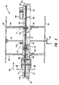
- FIG. 3 there is shown a top plan view of the conveyor module 50. It is seen to comprise a frame having side members 80 and 82 which are supported from the floor legs (not shown). Extending between the side members 80 and 82 of the frame are slide rails 84 and 86 which pass through transversely extending bores formed in a block member 88. Suitable bearings (not shown) may be disposed in the transversely extending bores to facilitate sliding of the block 88 to a desired position along the slide rails 84 and 86. Once a desired position of the block 88 is achieved during machine set-up to accommodate a carton of a given dimension, the block 88 can be locked in place relative to the frame by rotating the locking levers 90 and 92.
- a lead screw having a traveling nut 96 affixed to the block 88 is journaled for rotation between side plates 80 and 82. Rotation of the hand wheel 98 thus shifts the block 88 along the slide rails 84 and 86 in a direction determined by the direction of rotation of the hand wheel 98.
- the block 88 includes a first longitudinal channel 100 in which is disposed an endless chain 102.
- the chain 102 is deployed about a driven sprocket 104 and an idler sprocket 106.
- the sprocket 104 is adapted to be driven by a motor 108.
- the sprocket wheels 104 and 106 are journaled for rotation relative to the frame about first and second horizontal, parallel, spaced-apart axes 110 and 112.
- the length of chain 102 above the axes 110 and 112 may be referred to as the upper chain flight and the length of the endless chain disposed below the axes 110 and 112 is referred to herein as the lower chain flight.
- the block 88 includes a cam track 114 that can be considered to comprise a first segment 116 that is parallel to the upper chain flight over a first predetermined distance and a second segment 118 which is contiguous with the first segment but which converges toward the upper chain flight in the direction of travel of the upper chain flight.
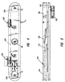
- Figure 5 which shows the underside of the block 88, in addition to the channel 100 in which the endless chain is disposed, it includes an additional cam track 120 that includes a first segment 122 that diverges away from the lower chain flight at a predetermined angle and is joined to a second segment 124 that extends parallel to the lower chain flight in the direction of travel of the lower chain flight.
- the chain 102 includes a coupler member 126 which is generally C-shaped and designed to straddle the chain 102.
- Chain link pins 128 pass through aligned apertures in the coupler 126 and in the chain links and a spring C-clip 130 is used to secure the link pins 128 in place.
- a tubular post 132 Projecting perpendicularly from the upper surface of the coupling member 126 is a tubular post 132 having a I.D. dimensioned to provide a predetermined clearance fit with a tubular stub shaft 134 (Fig. 8) that projects downwardly from the undersurface 136 of a generally rectangular product support plate 138.
- the product support plate 138 includes a rectangular cavity 140 formed inwardly from the upper surface 142 thereof. Disposed within the cavity are first and second cylindrical pedestals 144 and 146 having threaded bores 148 formed therein.
- An apertured top plate 150 (Fig. 9) fits within the cavity 140 and rests on the pedestals 144 and 146. Screws 152 inserted into the threaded bores 148 hold the plate 150 in place.
- the bottom surface of the plate 150 is spaced from the bottom of the product support plate 138 to create a vacuum plenum that is in fluid communication with the lumen of the tubular post 132.
- a vacuum is drawn at the base of the tubular post 132, a suction is created through the apertures in the plate 150 to attract and hold a carton or other product onto the upper surface of the product support plate 138.
- the product support plate 138 further includes laterally projecting arms 156 and 158 to provide additional support surface for a product being carried.
- a cylindrical stud 160 projects downward from the undersurface 136 of the arm 158 of the support plate 138 and affixed proximate the lower end of the stud 160 is a cam follower 162, which preferably comprises a ball bearing set having an outer race 164.
- the cam follower 162 depends from the arm 158 at a location that places the cam follower 162 in the cam track segment 116 which runs parallel to the endless chain 102. At this point, the longitudinal axis of the product support plate 138 is parallel to the chain axis. See Figure 3.
- a permanent magnet 166 is affixed to the block 88 adjacent the diverging segment 122 of the cam track. The permanent magnet attracts the cam follower 162 which then enters the segment 122 and ultimately enters and traverses the parallel segment 124 so that when the carrier traverses the sprocket 106, it will again be positioned like the product support plate 138 closest to the left end of the conveyor module 50 shown in Figure 3.
- an electromagnet air jet or a mechanical plunger to accomplish the same purpose.
- numeral 168 identifies a vacuum inlet to which a vacuum hose may be connected.
- This vacuum inlet leads through a bore in block 88 to the underside of the channel 100 in which the chain 102 resides.
- a suction is drawn through the apertures in the support plate 150, thus more firmly securing a product, such as a carton to the support plate as rotation occurs.
- the vacuum is released when the tubular stub shaft 134 leaves the vacuum chamber formed in the block 88 and, at this point, the product is picked up by a sweep conveyor (not shown) and transported through the gluing station 12"' ( Figure 1).
- the chain 102 has brackets 168 connected to each link.
- the brackets 168 include flanges 170 that are bent outwardly at 90° to the bracket wall and each of the flanges includes a pair of apertures as at 172.
- Plates 174 preferably formed from a plastic material exhibiting a low coefficient of friction are affixed to the flanges by pop rivets 176. The plates 174 overlap at their leading and trailing edges when the chain is moving in a horizontal direction, but do not interfere with one another as the chain traverses the sprockets 104 and 106.
Landscapes
- Engineering & Computer Science (AREA)
- Mechanical Engineering (AREA)
- Making Paper Articles (AREA)
- Chain Conveyers (AREA)
- Attitude Control For Articles On Conveyors (AREA)
- Supplying Of Containers To The Packaging Station (AREA)
- Intermediate Stations On Conveyors (AREA)
- Specific Conveyance Elements (AREA)
Claims (9)
- Fördermodul (50) zum Drehen von Produkten (12) während des Transports längs des Fördermoduls, mit:a) einem Rahmen (80, 82);b) einem ersten und zweiten Kettenrad (104, 106), die relativ zum Rahmen um eine erste bzw. zweite Achse (110, 112) drehbar gelagert sind, die horizontal, parallel und voneinander beabstandet angeordnet sind;c) einer Endloskette (102), die sich über das erste und zweite Kettenrad (104, 106) erstreckt, um eine obere und untere Kettenbahn zu definieren;d) einer im Allgemeinen rechteckigen Produkthalteplatte (138) mit einer oberen und unteren Hauptfläche (142, 136), wobei die Halteplatte an einem ersten Achsenelement (134) an einem Mittelpunkt der unteren Hauptfläche (136) befestigt ist und ein Nockenfolgeelement (162) auf einem zweiten Achsenelement (160) aufweist, das an der unteren Hauptfläche befestigt und zum ersten Achsenelement seitlich versetzt ist;e) einem Kopplungselement (126), das an der Kette (102) befestigt ist und von dieser betragen wird sowie mit dem ersten Achsenelement (134) schwenkbar verbunden ist, um eine Drehung des ersten Achsenelements um eine Längsachse des ersten Achsenelements zu ermöglichen;
dadurch gekennzeichnet, dass das Fördermodul ferner aufweist:f) eine Nockenspur (100), die am Rahmen gehaltert ist und einen ersten Abschnitt (116) aufweist, der über eine erste vorbestimmte Distanz parallel zur oberen Kettenbahn ist, und einen zweiten Abschnitt (118), der in Bewegungsrichtung der oberen Kettenbahn zur oberen Kettenbahn hin konvergiert, wobei das Nockenfolgeelement (162) ausgebildet ist, mit der Nockenspur (100) in Eingriff zu treten, um die Drehung der Produkthalteplatte (138) mit dem ersten Achsenelement (134) zu bewirken. - Fördermodul nach Anspruch 1, welches ferner aufweist:a) eine zusätzliche Nockenspur (120), die am Rahmen gehaltert ist und einen ersten Abschnitt (122) aufweist, der in Bewegungsrichtung der unteren Kettenbahn um einen vorbestimmten Winkel von der unteren Kettenbahn weg divergiert und mit einem zweiten Abschnitt (124) verbunden ist, der sich parallel zur unteren Kettenbahn erstreckt; undb) eine Einrichtung (166), die benachbart zum ersten Abschnitt (120) der zusätzlichen Nockenspur angeordnet ist, um zu bewirken, dass das Nockenfolgeelement (162) den ersten Abschnitt der zusätzlichen Nockenbahn durchläuft.
- Fördermodul nach Anspruch 2, wobei die Einrichtung (166), welche bewirkt, dass das Nockenfolgeelement (162) den ersten Abschnitt (122) der zusätzlichen Nockenbahn (120) durchläuft, auf das Nockenfolgeelement eine magnetische Kraft ausübt.
- Fördermodul nach Anspruch 1, das ferner einen Motor (108) aufweist, der mit dem ersten oder zweiten Kettenrad (104, 106) in Zugverbindung steht.
- Fördermodul nach Anspruch 1, welches ferner eine Einrichtung (168) aufweist, um ein Vakuum durch die Produkthalteplatte (138) hindurch herzustellen, um ein Produkt an der oberen Hauptfläche (142) der Produkthalteplatte anhaften zu lassen.
- Fördermodul nach Anspruch 5, wobei die Einrichtung zum Herstellen eines Vakuums durch die obere Hauptfläche (142) der Produkthalteplatte (138) hindurch eine Längsbohrung aufweist, die sich durch das erste Achsenelement (134) hindurch erstreckt, wobei die Bohrung mit einer Vakuumquelle (168) in Fluidverbindung ist; und wobei die obere Hauptfläche (142) der Halteplatte (138) ein Muster von hindurchgehenden Perforationen aufweist.
- Fördermodul nach Anspruch 2, welches ferner ein längliches, vom Rahmen (80, 82) gehaltenes Blockelement (88) mit im Allgemeinen rechtwinkligem Querschnitt aufweist, wobei das Blockelement eine obere und untere Oberfläche hat, die im Allgemeinen eben sind, sowie eine längliche Nut (100), die von der oberen und unteren ebenen Oberfläche nach innen ausgebildet ist und in der die obere bzw. untere Kettenbahn angeordnet ist,
wobei der erste Abschnitt (116) der Nockenspur (100) parallel zur Längsnut in der oberen ebenen Oberfläche ist und der zweite Abschnitt (118) vom ersten Abschnitt zur Längsnut in der oberen ebenen Oberfläche verläuft,
wobei der erste Abschnitt (122) der zusätzlichen Nockenspur (120) parallel zur Längsnut in der unteren ebenen Oberfläche ist und der zweite Abschnitt (124) von der Längsnut in der unteren ebenen Oberfläche zum ersten Abschnitt (122) der zusätzlichen Nockenspur (120) verläuft. - Fördermodul nach Anspruch 7, welches ferner eine Einrichtung (166) aufweist, die an der unteren Oberfläche des Blockelements (88) befestigt ist, um das Nockenfolgeelement (162) von der Längsnut (100), die innerhalb der unteren Oberfläche ausgebildet ist, in den zweiten Abschnitt (122) der zweiten Nockenspur (120) zu lenken, wenn die Produkthalteplatte (138) von der Endloskette benachbart zur unteren Oberfläche des Blockelements getragen wird.
- Fördermodul nach Anspruch 8, wobei die Einrichtung (166) einen Permanentmagneten oder einen Elektromagneten aufweist.
Applications Claiming Priority (2)
| Application Number | Priority Date | Filing Date | Title |
|---|---|---|---|
| US09/706,107 US6435332B1 (en) | 2000-11-03 | 2000-11-03 | Conveyor module for simultaneous translation and rotation of products |
| US706107 | 2000-11-03 |
Publications (3)
| Publication Number | Publication Date |
|---|---|
| EP1203736A2 EP1203736A2 (de) | 2002-05-08 |
| EP1203736A3 EP1203736A3 (de) | 2002-06-12 |
| EP1203736B1 true EP1203736B1 (de) | 2004-05-06 |
Family
ID=24836242
Family Applications (1)
| Application Number | Title | Priority Date | Filing Date |
|---|---|---|---|
| EP01307047A Expired - Lifetime EP1203736B1 (de) | 2000-11-03 | 2001-08-20 | Fördermodul zur gleichzeitigen übersetzen und drehen von Gegenständen |
Country Status (6)
| Country | Link |
|---|---|
| US (1) | US6435332B1 (de) |
| EP (1) | EP1203736B1 (de) |
| AT (1) | ATE265975T1 (de) |
| AU (1) | AU776859B2 (de) |
| CA (1) | CA2351039C (de) |
| DE (1) | DE60103116T2 (de) |
Families Citing this family (17)
| Publication number | Priority date | Publication date | Assignee | Title |
|---|---|---|---|---|
| WO2002088004A2 (en) * | 2001-04-30 | 2002-11-07 | United States Postal Service | Automated processing of bulk containers |
| GB0116175D0 (en) * | 2001-07-02 | 2001-08-22 | Ishida Europ Mfg Ltd | Reorientation |
| NL1023690C2 (nl) * | 2003-06-18 | 2004-12-21 | Meyn Food Proc Technology Bv | Hangtransporteur voor gevogelte. |
| US7055672B2 (en) * | 2003-11-28 | 2006-06-06 | The Horsley Company | Baggage positioner for baggage conveyor |
| SE526218C2 (sv) * | 2003-12-16 | 2005-08-02 | Tetra Laval Holdings & Finance | Anordning för vändning av behållare |
| US8100252B2 (en) * | 2006-12-14 | 2012-01-24 | Laitram, Llc | Object repositioning system |
| CN201071392Y (zh) * | 2007-07-13 | 2008-06-11 | 富港电子(东莞)有限公司 | 连续式溅镀机工件输送装置 |
| US8783000B2 (en) * | 2008-09-26 | 2014-07-22 | R. A. Jones & Co. Inc. | Rotating bucket for product handling apparatus |
| US9309017B2 (en) * | 2010-02-24 | 2016-04-12 | H. J. Paul Langen | Item loading apparatus |
| ES2480692T3 (es) * | 2011-10-31 | 2014-07-28 | Tetra Laval Holdings & Finance S.A. | Transportador para una unidad de manipulación de artículos, en particular para una unidad de plegado para la producción de envases de productos alimenticios vertibles |
| CN102897349B (zh) * | 2012-09-14 | 2015-08-19 | 浙江济民制药股份有限公司 | 一种硬口管输液袋加工流水线上的翻袋机构 |
| US10315376B2 (en) * | 2012-11-08 | 2019-06-11 | The C.W. Zumbiel Company | System and associated method for digital scoring of carton blanks |
| CA2873752C (en) | 2014-01-24 | 2021-03-09 | Axium Inc. | Product orientor |
| CN106458341B (zh) * | 2014-06-27 | 2019-04-02 | 印刷包装国际有限责任公司 | 具有旋转条板的连续运动包装机器 |
| IT201800010551A1 (it) * | 2018-11-23 | 2020-05-23 | Aper S R L | Metodo e dispositivo di spalmatura |
| CN110550480B (zh) * | 2019-08-28 | 2020-12-18 | 海宁市金石毛绒股份有限公司 | 一种纺织车间流水线用布料活动式悬挂输送机构 |
| CN114590594B (zh) * | 2022-03-14 | 2024-03-15 | 成都中光电科技有限公司 | 利于玻璃传输稳定的挡边杆装置 |
Family Cites Families (20)
| Publication number | Priority date | Publication date | Assignee | Title |
|---|---|---|---|---|
| US2643778A (en) | 1948-12-30 | 1953-06-30 | American Can Co | Conveyer mechanism with article turning units |
| US2779453A (en) * | 1954-04-22 | 1957-01-29 | Andrew Jergens Co | Article-manipulating apparatus for packaging machines |
| US2864281A (en) | 1956-01-12 | 1958-12-16 | Roy E Draper | Egg candling apparatus |
| CH394014A (de) * | 1961-01-05 | 1965-06-15 | Kema Keramikmaschinen Goerlitz | Vorrichtung zum Drehen und Umsetzen keramischer Formlinge |
| DE1178756B (de) | 1961-08-08 | 1964-09-24 | Hauni Werke Koerber & Co Kg | Vorrichtung zum Wenden einer der beiden eine Zigarettenmaschine verlassenden Reihen von Mundstueckzigaretten oder von anderen stabfoermigen Gegenstaenden |
| US3121362A (en) | 1962-08-06 | 1964-02-18 | Taylor Publishing Company | Trimming machine |
| US3187876A (en) | 1963-03-19 | 1965-06-08 | Continental Can Co | Can turning device |
| CH423446A (fr) | 1965-08-31 | 1966-10-31 | Bobst Fils Sa J | Mécanisme transporteur dans une machine pliant des découpes, par exemple de carton |
| US3783991A (en) | 1968-02-20 | 1974-01-08 | Smyth Mfg Co | Conveyor |
| US3847273A (en) | 1973-04-02 | 1974-11-12 | Scott Paper Co | Turning device for flexible web product |
| US4085839A (en) | 1976-08-30 | 1978-04-25 | Genevieve I. Hanscom, Robert M. Magnuson & Lois J. Thomson, Trustees Of The Estate Of Roy M. Magnuson | Apparatus for conveying and turning articles |
| US4246300A (en) | 1979-02-28 | 1981-01-20 | Reynolds Metals Company | Can transport |
| SE456082B (sv) | 1984-03-14 | 1988-09-05 | Sprinter System Ab | Anordning vid en forslutningsmaskin |
| CH673830A5 (de) | 1986-02-12 | 1990-04-12 | Will E C H Gmbh & Co | |
| JPH0524650Y2 (de) * | 1987-08-11 | 1993-06-23 | ||
| DE4402560C2 (de) | 1994-01-28 | 1997-07-03 | Windmoeller & Hoelscher | Vorrichtung zum Drehen von flachliegend voranbewegten Werkstücken |
| DE69820503T2 (de) | 1997-01-30 | 2004-11-04 | Totani Giken Kogyo Co. Ltd. | Blattzuführvorrichtung |
| DE19740809C2 (de) | 1997-09-17 | 2003-07-03 | Zf Sachs Ag | Druckplattenbaugruppe |
| DE19948704C1 (de) * | 1999-10-09 | 2001-02-01 | Boewe Systec Ag | Vorrichtung zum Drehen eines Papierstapels |
| US6290053B1 (en) * | 2000-01-07 | 2001-09-18 | Lockheed Martin Corporation | SMM (half tray) tray orientation device |
-
2000
- 2000-11-03 US US09/706,107 patent/US6435332B1/en not_active Expired - Lifetime
-
2001
- 2001-06-20 CA CA002351039A patent/CA2351039C/en not_active Expired - Fee Related
- 2001-08-20 AT AT01307047T patent/ATE265975T1/de not_active IP Right Cessation
- 2001-08-20 DE DE60103116T patent/DE60103116T2/de not_active Expired - Lifetime
- 2001-08-20 EP EP01307047A patent/EP1203736B1/de not_active Expired - Lifetime
- 2001-08-24 AU AU65437/01A patent/AU776859B2/en not_active Ceased
Also Published As
| Publication number | Publication date |
|---|---|
| ATE265975T1 (de) | 2004-05-15 |
| CA2351039A1 (en) | 2002-05-03 |
| AU776859B2 (en) | 2004-09-23 |
| US6435332B1 (en) | 2002-08-20 |
| CA2351039C (en) | 2006-09-19 |
| EP1203736A2 (de) | 2002-05-08 |
| AU6543701A (en) | 2002-05-09 |
| DE60103116T2 (de) | 2004-10-21 |
| DE60103116D1 (de) | 2004-06-09 |
| EP1203736A3 (de) | 2002-06-12 |
Similar Documents
| Publication | Publication Date | Title |
|---|---|---|
| EP1203736B1 (de) | Fördermodul zur gleichzeitigen übersetzen und drehen von Gegenständen | |
| US5454776A (en) | Carton bottom folder and sealer | |
| US8011495B2 (en) | Transfer device metering apparatus and methods | |
| KR920006489B1 (ko) | 판지상자 손잡이 부착장치 | |
| JP2981388B2 (ja) | 紙差し板および吸引ベルトを固定する方法 | |
| US5595043A (en) | Cartoner with selectively interchangeable tucking and gluing modules | |
| US6059709A (en) | Process for producing bags with folded over and secured handles by a fold-over rod extending at a right angle to the direction of transport | |
| US5535999A (en) | Apparatus for rotating a flat article through a desired angular orientation | |
| US20060070859A1 (en) | Conveyor system and method of using | |
| CN114735296A (zh) | 一种烟草包装机异型烟输送装置 | |
| CN214027437U (zh) | 一种纸质包装盒用围条的成型器 | |
| US4518379A (en) | Apparatus and method for joining individual blanks | |
| KR910007759A (ko) | 관형 카아톤 브랭크의 직립장치 | |
| JP4070760B2 (ja) | 段ボールシートの開函装置 | |
| US20030005566A1 (en) | Method and apparatus for assembling and packing small-sized articles | |
| JP3623535B2 (ja) | 製函装置における段ボールシートの開函装置 | |
| JP2019064698A (ja) | 糊付け装置およびそれを備えた箱詰め装置 | |
| JP3691860B2 (ja) | 段ボール箱の製函方法 | |
| JPH0376657B2 (de) | ||
| CN112356497A (zh) | 一种全自动纸质包装盒成型设备及方法 | |
| JP4070759B2 (ja) | 段ボールシートの供給装置 | |
| CN218114128U (zh) | 一种关节输送机的输送结构 | |
| JPH0346860Y2 (de) | ||
| US3905282A (en) | Process and apparatus for assembling a bulk container | |
| CN214419713U (zh) | 一种纸质包装盒用围条的成型头 |
Legal Events
| Date | Code | Title | Description |
|---|---|---|---|
| PUAI | Public reference made under article 153(3) epc to a published international application that has entered the european phase |
Free format text: ORIGINAL CODE: 0009012 |
|
| PUAL | Search report despatched |
Free format text: ORIGINAL CODE: 0009013 |
|
| AK | Designated contracting states |
Kind code of ref document: A2 Designated state(s): AT BE CH CY DE DK ES FI FR GB GR IE IT LI LU MC NL PT SE TR |
|
| AX | Request for extension of the european patent |
Free format text: AL;LT;LV;MK;RO;SI |
|
| AK | Designated contracting states |
Kind code of ref document: A3 Designated state(s): AT BE CH CY DE DK ES FI FR GB GR IE IT LI LU MC NL PT SE TR |
|
| AX | Request for extension of the european patent |
Free format text: AL;LT;LV;MK;RO;SI |
|
| RIC1 | Information provided on ipc code assigned before grant |
Free format text: 7B 65G 47/244 A, 7B 65G 47/24 B |
|
| 17P | Request for examination filed |
Effective date: 20020830 |
|
| 17Q | First examination report despatched |
Effective date: 20021127 |
|
| AKX | Designation fees paid |
Designated state(s): AT BE CH CY DE DK ES FI FR GB GR IE IT LI LU MC NL PT SE TR |
|
| GRAP | Despatch of communication of intention to grant a patent |
Free format text: ORIGINAL CODE: EPIDOSNIGR1 |
|
| GRAS | Grant fee paid |
Free format text: ORIGINAL CODE: EPIDOSNIGR3 |
|
| GRAA | (expected) grant |
Free format text: ORIGINAL CODE: 0009210 |
|
| AK | Designated contracting states |
Kind code of ref document: B1 Designated state(s): AT BE CH CY DE DK ES FI FR GB GR IE IT LI LU MC NL PT SE TR |
|
| PG25 | Lapsed in a contracting state [announced via postgrant information from national office to epo] |
Ref country code: TR Free format text: LAPSE BECAUSE OF FAILURE TO SUBMIT A TRANSLATION OF THE DESCRIPTION OR TO PAY THE FEE WITHIN THE PRESCRIBED TIME-LIMIT Effective date: 20040506 Ref country code: AT Free format text: LAPSE BECAUSE OF FAILURE TO SUBMIT A TRANSLATION OF THE DESCRIPTION OR TO PAY THE FEE WITHIN THE PRESCRIBED TIME-LIMIT Effective date: 20040506 Ref country code: CY Free format text: LAPSE BECAUSE OF FAILURE TO SUBMIT A TRANSLATION OF THE DESCRIPTION OR TO PAY THE FEE WITHIN THE PRESCRIBED TIME-LIMIT Effective date: 20040506 Ref country code: BE Free format text: LAPSE BECAUSE OF FAILURE TO SUBMIT A TRANSLATION OF THE DESCRIPTION OR TO PAY THE FEE WITHIN THE PRESCRIBED TIME-LIMIT Effective date: 20040506 Ref country code: NL Free format text: LAPSE BECAUSE OF FAILURE TO SUBMIT A TRANSLATION OF THE DESCRIPTION OR TO PAY THE FEE WITHIN THE PRESCRIBED TIME-LIMIT Effective date: 20040506 |
|
| REG | Reference to a national code |
Ref country code: GB Ref legal event code: FG4D |
|
| REG | Reference to a national code |
Ref country code: CH Ref legal event code: EP |
|
| REF | Corresponds to: |
Ref document number: 60103116 Country of ref document: DE Date of ref document: 20040609 Kind code of ref document: P |
|
| REG | Reference to a national code |
Ref country code: IE Ref legal event code: FG4D |
|
| PGFP | Annual fee paid to national office [announced via postgrant information from national office to epo] |
Ref country code: MC Payment date: 20040728 Year of fee payment: 4 |
|
| REG | Reference to a national code |
Ref country code: SE Ref legal event code: TRGR |
|
| PG25 | Lapsed in a contracting state [announced via postgrant information from national office to epo] |
Ref country code: DK Free format text: LAPSE BECAUSE OF FAILURE TO SUBMIT A TRANSLATION OF THE DESCRIPTION OR TO PAY THE FEE WITHIN THE PRESCRIBED TIME-LIMIT Effective date: 20040806 Ref country code: GR Free format text: LAPSE BECAUSE OF FAILURE TO SUBMIT A TRANSLATION OF THE DESCRIPTION OR TO PAY THE FEE WITHIN THE PRESCRIBED TIME-LIMIT Effective date: 20040806 |
|
| PGFP | Annual fee paid to national office [announced via postgrant information from national office to epo] |
Ref country code: IE Payment date: 20040811 Year of fee payment: 4 |
|
| PGFP | Annual fee paid to national office [announced via postgrant information from national office to epo] |
Ref country code: DK Payment date: 20040813 Year of fee payment: 4 |
|
| REG | Reference to a national code |
Ref country code: CH Ref legal event code: NV Representative=s name: R. A. EGLI & CO. PATENTANWAELTE |
|
| PG25 | Lapsed in a contracting state [announced via postgrant information from national office to epo] |
Ref country code: ES Free format text: LAPSE BECAUSE OF FAILURE TO SUBMIT A TRANSLATION OF THE DESCRIPTION OR TO PAY THE FEE WITHIN THE PRESCRIBED TIME-LIMIT Effective date: 20040817 |
|
| PGFP | Annual fee paid to national office [announced via postgrant information from national office to epo] |
Ref country code: LU Payment date: 20040826 Year of fee payment: 4 |
|
| NLV1 | Nl: lapsed or annulled due to failure to fulfill the requirements of art. 29p and 29m of the patents act | ||
| ET | Fr: translation filed | ||
| PLBE | No opposition filed within time limit |
Free format text: ORIGINAL CODE: 0009261 |
|
| STAA | Information on the status of an ep patent application or granted ep patent |
Free format text: STATUS: NO OPPOSITION FILED WITHIN TIME LIMIT |
|
| 26N | No opposition filed |
Effective date: 20050208 |
|
| PG25 | Lapsed in a contracting state [announced via postgrant information from national office to epo] |
Ref country code: LU Free format text: LAPSE BECAUSE OF NON-PAYMENT OF DUE FEES Effective date: 20050820 |
|
| PG25 | Lapsed in a contracting state [announced via postgrant information from national office to epo] |
Ref country code: IE Free format text: LAPSE BECAUSE OF NON-PAYMENT OF DUE FEES Effective date: 20050822 |
|
| PG25 | Lapsed in a contracting state [announced via postgrant information from national office to epo] |
Ref country code: MC Free format text: LAPSE BECAUSE OF NON-PAYMENT OF DUE FEES Effective date: 20050831 |
|
| REG | Reference to a national code |
Ref country code: IE Ref legal event code: MM4A |
|
| PG25 | Lapsed in a contracting state [announced via postgrant information from national office to epo] |
Ref country code: PT Free format text: LAPSE BECAUSE OF NON-PAYMENT OF DUE FEES Effective date: 20041006 |
|
| REG | Reference to a national code |
Ref country code: FR Ref legal event code: PLFP Year of fee payment: 16 |
|
| REG | Reference to a national code |
Ref country code: FR Ref legal event code: PLFP Year of fee payment: 17 |
|
| REG | Reference to a national code |
Ref country code: DE Ref legal event code: R082 Ref document number: 60103116 Country of ref document: DE Representative=s name: FLACH BAUER STAHL PATENTANWAELTE PARTNERSCHAFT, DE |
|
| REG | Reference to a national code |
Ref country code: FR Ref legal event code: PLFP Year of fee payment: 18 |
|
| PGFP | Annual fee paid to national office [announced via postgrant information from national office to epo] |
Ref country code: FR Payment date: 20180824 Year of fee payment: 18 Ref country code: IT Payment date: 20180823 Year of fee payment: 18 |
|
| PGFP | Annual fee paid to national office [announced via postgrant information from national office to epo] |
Ref country code: GB Payment date: 20180828 Year of fee payment: 18 Ref country code: SE Payment date: 20180827 Year of fee payment: 18 Ref country code: FI Payment date: 20180821 Year of fee payment: 18 Ref country code: CH Payment date: 20180827 Year of fee payment: 18 |
|
| PGFP | Annual fee paid to national office [announced via postgrant information from national office to epo] |
Ref country code: DE Payment date: 20181024 Year of fee payment: 18 |
|
| REG | Reference to a national code |
Ref country code: DE Ref legal event code: R119 Ref document number: 60103116 Country of ref document: DE |
|
| REG | Reference to a national code |
Ref country code: FI Ref legal event code: MAE |
|
| REG | Reference to a national code |
Ref country code: SE Ref legal event code: EUG |
|
| GBPC | Gb: european patent ceased through non-payment of renewal fee |
Effective date: 20190820 |
|
| PG25 | Lapsed in a contracting state [announced via postgrant information from national office to epo] |
Ref country code: SE Free format text: LAPSE BECAUSE OF NON-PAYMENT OF DUE FEES Effective date: 20190821 Ref country code: FI Free format text: LAPSE BECAUSE OF NON-PAYMENT OF DUE FEES Effective date: 20190820 |
|
| PG25 | Lapsed in a contracting state [announced via postgrant information from national office to epo] |
Ref country code: LI Free format text: LAPSE BECAUSE OF NON-PAYMENT OF DUE FEES Effective date: 20190831 Ref country code: CH Free format text: LAPSE BECAUSE OF NON-PAYMENT OF DUE FEES Effective date: 20190831 |
|
| PG25 | Lapsed in a contracting state [announced via postgrant information from national office to epo] |
Ref country code: FR Free format text: LAPSE BECAUSE OF NON-PAYMENT OF DUE FEES Effective date: 20190831 Ref country code: DE Free format text: LAPSE BECAUSE OF NON-PAYMENT OF DUE FEES Effective date: 20200303 |
|
| PG25 | Lapsed in a contracting state [announced via postgrant information from national office to epo] |
Ref country code: IT Free format text: LAPSE BECAUSE OF NON-PAYMENT OF DUE FEES Effective date: 20190820 Ref country code: GB Free format text: LAPSE BECAUSE OF NON-PAYMENT OF DUE FEES Effective date: 20190820 |