EP1203142B1 - Brennkraftmaschine mit sekundärlufteinblassystem - Google Patents
Brennkraftmaschine mit sekundärlufteinblassystem Download PDFInfo
- Publication number
- EP1203142B1 EP1203142B1 EP00951490A EP00951490A EP1203142B1 EP 1203142 B1 EP1203142 B1 EP 1203142B1 EP 00951490 A EP00951490 A EP 00951490A EP 00951490 A EP00951490 A EP 00951490A EP 1203142 B1 EP1203142 B1 EP 1203142B1
- Authority
- EP
- European Patent Office
- Prior art keywords
- module
- internal combustion
- combustion engine
- line
- secondary air
- Prior art date
- Legal status (The legal status is an assumption and is not a legal conclusion. Google has not performed a legal analysis and makes no representation as to the accuracy of the status listed.)
- Expired - Lifetime
Links
Images

Classifications
-
- F—MECHANICAL ENGINEERING; LIGHTING; HEATING; WEAPONS; BLASTING
- F02—COMBUSTION ENGINES; HOT-GAS OR COMBUSTION-PRODUCT ENGINE PLANTS
- F02M—SUPPLYING COMBUSTION ENGINES IN GENERAL WITH COMBUSTIBLE MIXTURES OR CONSTITUENTS THEREOF
- F02M35/00—Combustion-air cleaners, air intakes, intake silencers, or induction systems specially adapted for, or arranged on, internal-combustion engines
- F02M35/10—Air intakes; Induction systems
- F02M35/10209—Fluid connections to the air intake system; their arrangement of pipes, valves or the like
- F02M35/10229—Fluid connections to the air intake system; their arrangement of pipes, valves or the like the intake system acting as a vacuum or overpressure source for auxiliary devices, e.g. brake systems; Vacuum chambers
-
- F—MECHANICAL ENGINEERING; LIGHTING; HEATING; WEAPONS; BLASTING
- F01—MACHINES OR ENGINES IN GENERAL; ENGINE PLANTS IN GENERAL; STEAM ENGINES
- F01N—GAS-FLOW SILENCERS OR EXHAUST APPARATUS FOR MACHINES OR ENGINES IN GENERAL; GAS-FLOW SILENCERS OR EXHAUST APPARATUS FOR INTERNAL COMBUSTION ENGINES
- F01N3/00—Exhaust or silencing apparatus having means for purifying, rendering innocuous, or otherwise treating exhaust
- F01N3/08—Exhaust or silencing apparatus having means for purifying, rendering innocuous, or otherwise treating exhaust for rendering innocuous
- F01N3/10—Exhaust or silencing apparatus having means for purifying, rendering innocuous, or otherwise treating exhaust for rendering innocuous by thermal or catalytic conversion of noxious components of exhaust
- F01N3/24—Exhaust or silencing apparatus having means for purifying, rendering innocuous, or otherwise treating exhaust for rendering innocuous by thermal or catalytic conversion of noxious components of exhaust characterised by constructional aspects of converting apparatus
- F01N3/30—Arrangements for supply of additional air
- F01N3/32—Arrangements for supply of additional air using air pump
-
- F—MECHANICAL ENGINEERING; LIGHTING; HEATING; WEAPONS; BLASTING
- F02—COMBUSTION ENGINES; HOT-GAS OR COMBUSTION-PRODUCT ENGINE PLANTS
- F02B—INTERNAL-COMBUSTION PISTON ENGINES; COMBUSTION ENGINES IN GENERAL
- F02B75/00—Other engines
- F02B75/16—Engines characterised by number of cylinders, e.g. single-cylinder engines
- F02B75/18—Multi-cylinder engines
- F02B75/22—Multi-cylinder engines with cylinders in V, fan, or star arrangement
-
- F—MECHANICAL ENGINEERING; LIGHTING; HEATING; WEAPONS; BLASTING
- F02—COMBUSTION ENGINES; HOT-GAS OR COMBUSTION-PRODUCT ENGINE PLANTS
- F02M—SUPPLYING COMBUSTION ENGINES IN GENERAL WITH COMBUSTIBLE MIXTURES OR CONSTITUENTS THEREOF
- F02M26/00—Engine-pertinent apparatus for adding exhaust gases to combustion-air, main fuel or fuel-air mixture, e.g. by exhaust gas recirculation [EGR] systems
- F02M26/13—Arrangement or layout of EGR passages, e.g. in relation to specific engine parts or for incorporation of accessories
- F02M26/36—Arrangement or layout of EGR passages, e.g. in relation to specific engine parts or for incorporation of accessories with means for adding fluids other than exhaust gas to the recirculation passage; with reformers
-
- F—MECHANICAL ENGINEERING; LIGHTING; HEATING; WEAPONS; BLASTING
- F02—COMBUSTION ENGINES; HOT-GAS OR COMBUSTION-PRODUCT ENGINE PLANTS
- F02M—SUPPLYING COMBUSTION ENGINES IN GENERAL WITH COMBUSTIBLE MIXTURES OR CONSTITUENTS THEREOF
- F02M26/00—Engine-pertinent apparatus for adding exhaust gases to combustion-air, main fuel or fuel-air mixture, e.g. by exhaust gas recirculation [EGR] systems
- F02M26/13—Arrangement or layout of EGR passages, e.g. in relation to specific engine parts or for incorporation of accessories
- F02M26/41—Arrangement or layout of EGR passages, e.g. in relation to specific engine parts or for incorporation of accessories characterised by the arrangement of the recirculation passage in relation to the engine, e.g. to cylinder heads, liners, spark plugs or manifolds; characterised by the arrangement of the recirculation passage in relation to specially adapted combustion chambers
-
- F—MECHANICAL ENGINEERING; LIGHTING; HEATING; WEAPONS; BLASTING
- F01—MACHINES OR ENGINES IN GENERAL; ENGINE PLANTS IN GENERAL; STEAM ENGINES
- F01N—GAS-FLOW SILENCERS OR EXHAUST APPARATUS FOR MACHINES OR ENGINES IN GENERAL; GAS-FLOW SILENCERS OR EXHAUST APPARATUS FOR INTERNAL COMBUSTION ENGINES
- F01N2470/00—Structure or shape of gas passages, pipes or tubes
- F01N2470/28—Tubes being formed by moulding or casting x
-
- F—MECHANICAL ENGINEERING; LIGHTING; HEATING; WEAPONS; BLASTING
- F01—MACHINES OR ENGINES IN GENERAL; ENGINE PLANTS IN GENERAL; STEAM ENGINES
- F01N—GAS-FLOW SILENCERS OR EXHAUST APPARATUS FOR MACHINES OR ENGINES IN GENERAL; GAS-FLOW SILENCERS OR EXHAUST APPARATUS FOR INTERNAL COMBUSTION ENGINES
- F01N2530/00—Selection of materials for tubes, chambers or housings
- F01N2530/06—Aluminium or alloys thereof
-
- F—MECHANICAL ENGINEERING; LIGHTING; HEATING; WEAPONS; BLASTING
- F01—MACHINES OR ENGINES IN GENERAL; ENGINE PLANTS IN GENERAL; STEAM ENGINES
- F01N—GAS-FLOW SILENCERS OR EXHAUST APPARATUS FOR MACHINES OR ENGINES IN GENERAL; GAS-FLOW SILENCERS OR EXHAUST APPARATUS FOR INTERNAL COMBUSTION ENGINES
- F01N2530/00—Selection of materials for tubes, chambers or housings
- F01N2530/18—Plastics material, e.g. polyester resin
-
- F—MECHANICAL ENGINEERING; LIGHTING; HEATING; WEAPONS; BLASTING
- F02—COMBUSTION ENGINES; HOT-GAS OR COMBUSTION-PRODUCT ENGINE PLANTS
- F02D—CONTROLLING COMBUSTION ENGINES
- F02D9/00—Controlling engines by throttling air or fuel-and-air induction conduits or exhaust conduits
- F02D9/02—Controlling engines by throttling air or fuel-and-air induction conduits or exhaust conduits concerning induction conduits
- F02D2009/0201—Arrangements; Control features; Details thereof
- F02D2009/0279—Throttle valve control for intake system with two parallel air flow paths, each controlled by a throttle, e.g. a resilient flap disposed on a throttle
-
- F—MECHANICAL ENGINEERING; LIGHTING; HEATING; WEAPONS; BLASTING
- F02—COMBUSTION ENGINES; HOT-GAS OR COMBUSTION-PRODUCT ENGINE PLANTS
- F02D—CONTROLLING COMBUSTION ENGINES
- F02D9/00—Controlling engines by throttling air or fuel-and-air induction conduits or exhaust conduits
- F02D9/02—Controlling engines by throttling air or fuel-and-air induction conduits or exhaust conduits concerning induction conduits
- F02D2009/0201—Arrangements; Control features; Details thereof
- F02D2009/0283—Throttle in the form of an expander
-
- F—MECHANICAL ENGINEERING; LIGHTING; HEATING; WEAPONS; BLASTING
- F02—COMBUSTION ENGINES; HOT-GAS OR COMBUSTION-PRODUCT ENGINE PLANTS
- F02M—SUPPLYING COMBUSTION ENGINES IN GENERAL WITH COMBUSTIBLE MIXTURES OR CONSTITUENTS THEREOF
- F02M26/00—Engine-pertinent apparatus for adding exhaust gases to combustion-air, main fuel or fuel-air mixture, e.g. by exhaust gas recirculation [EGR] systems
- F02M26/13—Arrangement or layout of EGR passages, e.g. in relation to specific engine parts or for incorporation of accessories
- F02M26/17—Arrangement or layout of EGR passages, e.g. in relation to specific engine parts or for incorporation of accessories in relation to the intake system
- F02M26/21—Arrangement or layout of EGR passages, e.g. in relation to specific engine parts or for incorporation of accessories in relation to the intake system with EGR valves located at or near the connection to the intake system
-
- Y—GENERAL TAGGING OF NEW TECHNOLOGICAL DEVELOPMENTS; GENERAL TAGGING OF CROSS-SECTIONAL TECHNOLOGIES SPANNING OVER SEVERAL SECTIONS OF THE IPC; TECHNICAL SUBJECTS COVERED BY FORMER USPC CROSS-REFERENCE ART COLLECTIONS [XRACs] AND DIGESTS
- Y02—TECHNOLOGIES OR APPLICATIONS FOR MITIGATION OR ADAPTATION AGAINST CLIMATE CHANGE
- Y02T—CLIMATE CHANGE MITIGATION TECHNOLOGIES RELATED TO TRANSPORTATION
- Y02T10/00—Road transport of goods or passengers
- Y02T10/10—Internal combustion engine [ICE] based vehicles
- Y02T10/12—Improving ICE efficiencies
Definitions
- the invention relates to an internal combustion engine which has a line system for secondary air for introduction to the exhaust tract, according to the genus of Claim 1.
- the internal combustion engine additionally contain a pipe system for exhaust gas recirculation.
- the invention also relates to a line module for integration into the internal combustion engine according to the preamble of claim 13.
- Such a secondary air intake system is e.g. B. from WO 97/38212.
- the basic structure can be seen in Figure 2.
- the secondary air is through a line 13 to the intake tract of the internal combustion engine removed from the clean side in front of a throttle valve 33 and by a compressor 26 pumped into the exhaust area 31 via a line 14.
- a turbine 35 which is the pressure difference that is in the intake manifold through the throttle valve 33 sets, takes advantage.
- exhaust gas recirculation systems are used especially in the partial load range of the internal combustion engine, which lead to a reduction in NO x .
- Such a system can, for. B. EP 596 855 A1.
- exhaust gas is introduced into the intake tract 14 of an internal combustion engine 1 through a valve 19 and mixes with the intake air. This return reduces the combustion temperature and thus reduces the formation of nitrogen oxides.
- These systems are also implemented using pipes, valves and connecting elements.
- the lines for secondary air and exhaust gas recirculation can go into the cylinder head to get integrated.
- This idea is e.g. B. proposed in US 4,267,812.
- the cylinder head can be designed as a one-part or multi-part casting be, the channels being formed by the mold. This allows Save installation space for the air duct systems. You can also reduce weight to reach. To a certain extent, the Assembly effort for the line system at least for those in the cylinder head integrated areas.
- US 5,640,848 also proposes the lines for secondary air and exhaust gas recirculation to integrate into the cylinder head.
- the cylinder head can do the same be designed as a one-piece or multi-part casting, the channels are formed by the mold. It continues to suggest the number reduce the pipes by using the pipe for the exhaust gas recirculation and the duct for the secondary air from a shared Line is formed. This is possible because the operating states of the Internal combustion engine with exhaust gas recirculation or secondary air injection never occur simultaneously.
- valves, compressors and control devices required for the air duct systems cannot be easily integrated into the cylinder head become.
- This area of the internal combustion engine is already extraordinary complex design, since assemblies of different functions confined space.
- the inlet and Exhaust valves for the cylinders their control and drive to accommodate there.
- Sufficient oil lubrication is required for these mechanical parts to be guaranteed.
- Oil separation as well as cylinder head cooling are housed in this engine area.
- the Control and regulation for secondary air or exhaust gas recirculation systems in line sections housed, which are outside the cylinder head and a connection from this to the intake manifold area in front of the throttle valve or the exhaust system.
- there is an increased assembly and Manufacturing effort there is an increased assembly and Manufacturing effort.
- the object of the invention is therefore a line system for an internal combustion engine to create secondary air injection and / or exhaust gas recirculation, which is inexpensive to manufacture and reliable in function.
- This object is solved by the features of claims 1 and 12. Further a line module is claimed according to claim 13, which for Installation in an internal combustion engine is suitable.
- the internal combustion engine according to the invention has at least one line system for secondary air, which is constructed as already described.
- An internal combustion engine is attached to a module, which has at least one compressor duct with one connection for each supply line, one connection for one Compressor and a line section of the intake tract united.
- this can on Intake pipe are attached so that the air from the intake duct of the intake tract is passed through the line section into the intake manifold.
- the module in other sections of the Intake tract conceivable.
- a compressor can supply secondary air to either the intake tract, in particular behind the air filter or another part of the engine compartment. This is attached to the compressor port, which allows air to enter the module is pumped.
- Hydrodynamic fluid machines come as compressors, but also all other types of pumping, e.g. by an electric motor can be driven.
- the air passes through from the compressor connection a compressor channel and exits the module through the connection to to get into the supply line leading to the exhaust. With exhaust is the broadest Meaning the entire discharge tract for the combustion gases, started meant by the cylinder outlets. If the cylinders are divided into several Cylinder banks can also have multiple supply lines on the internal combustion engine be provided.
- the compressor duct can then be inside branch of the module, which reduces the effort required to connect pipe switches is saved, and have one connection per feed line.
- the use of the module described has several advantages. To my results from the direct connection to the intake manifold or to the engine block the internal combustion engine, especially the cylinder head, an extraordinary compact design. This not only saves installation space but also shortens it additionally the route. This allows the flow resistance of the Pipe system can be reduced, especially since the compressor channels are streamlined can be optimized. The streamlined design of the lines leads to shorter response times of the system and thus to one improved function of the internal combustion engine.
- the module can be pre-assembled Unit z. B. from a system supplier for final assembly of the Internal combustion engine can be delivered. This creates opportunities for errors avoided, which can occur during final assembly. In addition, due to a favorable division of labor a higher efficiency in the production of the Reach the internal combustion engine.
- the module can even be delivered before delivery be attached to the intake manifold. Another option is run the module as an integral part of the intake manifold. A part of Channel structures and connections can then through the housing parts of the intake manifold be formed and supplemented, for example, by a cover.
- the supply lines of the internal combustion engine can be integrated in the cylinder head his. In this case, a connection or integration of the module is both to the intake manifold as well as to the cylinder head. This allows the Internal combustion engine can be made even more compact. Lead the supply lines to the exhaust of the internal combustion engine. In this context, with Exhaust the entire exhaust route of the combustion gases from the cylinder heads meant.
- the secondary air is advantageously introduced upstream of the catalytic converter, to improve its behavior in the cold start phase.
- the compressor connection be designed such that the compressor at least partially in the module can be integrated.
- the housing shell for its impeller be implemented as part of the module. It will manufacture the corresponding one Housing shells saved on the compressor. Is the module as a casting executed, there is no additional manufacturing effort.
- the module can be made of plastic or light metal, e.g. Aluminum become.
- the A drive that uses combustion air in the intake tract results in a special one Favorable embodiment of the invention in that a turbine channel in the Module is integrated, which opens into the line section of the intake manifold.
- the other end of the turbine duct is formed by a turbine connection, deriving the drive air of the turbine and its assembly on Module guaranteed.
- a supply line from the intake tract (before the throttle valve) towards the turbine can be integrated into the module. This will the idea of integration according to the invention continued.
- the turbine at the turbine connection in the for the compressor way already described can be partially integrated into the module.
- the housing shells of the module can even the entire turbine compressor unit can be integrated into the module. hereby a particularly high level of component integration can be achieved.
- control valves for the Secondary air volume can be at least partially integrated into the module.
- appropriate connections can be provided for this, whereby the Component effort for the secondary air system can be further reduced can.
- module valve seats can be provided, with the Commercially available valve body module can be attached.
- the check valves necessary in the feed line be moved. Accordingly, some of these can be in the feed line and partially integrated in the module or even completely in the module.
- a control valve for the turbines which is also in the way described can be integrated into the module.
- the control valve for the turbine in the broader sense is also for controlling the amount of secondary air necessary.
- the control valves can be used as switching valves (positions on and closed) and be designed as stepless valves.
- the stepless one is advantageous Version, as this means that the secondary air volume for each operating state of the Internal combustion engine can be metered optimally.
- an exhaust duct be integrated into the module, which is the supply of the exhaust gas in the line section of the module guaranteed.
- the otherwise necessary is also omitted here Connection effort.
- the necessary can be advantageous Recirculation valve for the exhaust gas can be at least partially integrated in the module.
- the integration of the throttle valve in the line section of the module is particularly advantageous.
- the throttle valve itself is designed as a module, it can easily be attached to the connection of the module to the intake manifold or to the intake tract in front of the intake manifold.
- This arrangement is also advantageous for the introduction of the exhaust gases, since thorough mixing with the intake air is achieved.
- the confluence of the exhaust duct in the line section can be designed cost-effectively from the point of view of fluid mechanics with regard to an optimal mixing of the exhaust gas with the intake air.
- Particularly advantageous is an arrangement in which the throttle valve is attached to one side of the module, the exhaust duct and the turbine duct are fed to the module in the subsequent line section and the collecting space of the intake manifold begins at the other end of the line section.
- the idea of integration can be according to one Another embodiment of the invention also directly on the internal combustion engine realize. This is achieved in that the exhaust gas recirculation at least is partially formed by the supply line for the secondary air line is provided. This can save cable routes, with the common Section of the pipe systems either for exhaust gas extraction from the Exhaust or for secondary air feed into the exhaust is used.
- This Construction variant takes advantage of the fact that the operating states the internal combustion engine with exhaust gas recirculation or secondary air injection never occur at the same time. This design of the invention leads accordingly the task of saving pipeline routes with the advantages of space and component savings already described.
- a module for an internal combustion engine is suitable in the described Arrangements of the internal combustion engine to be installed.
- ES carries the invention Characteristics.
- the module can also be at least partially formed by the intake manifold housing become. This further supports the idea of integration. It can e.g. Connections between module and intake manifold housing saved become. Ideally, the entire module is part of the intake manifold housing. The housing structure the suction pipe can then be manufactured as a whole. manufacturing steps for the production of an additional module are therefore eliminated.
- the feed line 29 is used simultaneously for the exhaust gas removal.
- the exhaust gas enters the module 15 through the connection 28, the check valve 27 prevents a return line to the compressor. From the compressor duct 25 branches off, however, an exhaust duct 30, which an introduction of the exhaust gas into the Line section 14 shortly behind the throttle valve 13 allows. For controlling a recirculation valve 31 is provided for the exhaust gas flow.
- the compressor 23 is driven by a turbine 32.
- This uses the pressure difference in the intake tract 11 caused by the throttle valve 13, by taking intake air through a supply line 33 in front of the throttle valve, which via a turbine connection 34 in a turbine duct 35, the part of Module 15 and in the line section 14 behind the throttle valve 13th flows into the intake tract 11.
- a turbine duct Control valve 26b provided.
- the throttle valve 13 has an actuator 36 stepless adjustment.
- FIG. 2 shows a schematic representation of the spatial arrangement Remove all components involved in the internal combustion engine according to FIG. 1.
- This example shows an engine block 37 with a V-shaped arrangement of the cylinders on two cylinder banks 38.
- the individual components are identified by the reference numerals marked according to Figure 1 and will therefore not be repeated described. However, due to the geometrical arrangement following peculiarities.
- the feed line 29 cannot be seen since it is integrated in the cylinder head.
- the module is fastened with the connections 28.
- Module 15 is disc-shaped. It is flanged to the end of the suction pipe, whereby the line section 14 into an inlet 40 in the collecting space of the intake manifold empties.
- the throttle valve attached to a receptacle 41.
- the module can be an integral part of the Suction pipe to be executed. This eliminates a flange connection between Module and intake manifold. Instead of the disc-shaped structure, the integrated Module e.g. produced together with the suction tube using the lost-core technique become.
- the branching of the exhaust duct 30 from the compressor duct takes place outside of the module body.
- the return valve 31 is on the visible portion of the Exhaust gas duct 30 attached and leads into the base body 42. Is located there a second section of the exhaust duct 31, which is not visible in FIG. 2 is.
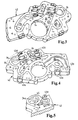
- a possible construction of the base body 42 for the module can be seen in the figures Remove 3 and 4.
- the two sides of the body can be seen, both being provided with end plates so that they are closed Form channel structures.
- the base body could be part of the Suction pipe housing be executed, whereby one of the end plates are omitted would.
- the channel sections in the module are identified by the reference numerals provided according to Figure 1 and should not be described in more detail become. However, there are the following special features.
- the extremely short line section 14 is striking. This is no longer than the base body 42 is thick. In this short section lets both the supply of the turbine duct 35 and the exhaust duct 30 realize.
- the base body can also have the Throttle valve can be attached. This extends the line section by the amount of throttle module thickness.
- the throttle valve can be used as Part of the module can be understood.
- the base body 42 has various valve connections 43a to 43d. These are in particular valve connections 43a for the check valves 27, a valve connection 43b for the return valve 31, a valve connection 43c for the control valve 26a and a valve connection 43d for the control valve 26b.
- the valve connection 43b and the turbine connection 34 and the compressor connection 24 are openings in the end plate of the base body, not shown 42 executed and therefore only represented by dashed circles.
- b valve seats 44 are further provided in the base body 42. This enables a partial integration of these valves in the base body.
- valve seats work with the valve disks of the control valves, not shown 26a, b together, which are inserted into the base body by the receptacles 43c, d become.
- FIG. 5 shows an alternative embodiment of the base body 42.
- the turbine connection 34a is designed such that the turbine blade wheel in can extend the base body 42. This will make a shell the turbine saved.
- the turbine connection 34a corresponds to the outer contours the turbine wheel of the turbine, not shown, funnel-shaped educated. It opens directly into the turbine duct 35.
- a corresponding one Connection channel 45 is shown in dashed lines.
Description
Besonders vorteilhaft ist dabei eine Anordnung, bei der die Drosselklappe an der einen Seite des Moduls angebracht ist, im darauf folgenden Leitungsabschnitt im Modul der Abgaskanal und der Turbinenkanal zugeführt wird und am anderen Ende des Leitungsabschnittes der Sammelraum des Saugrohr beginnt.
- Figur 1
- das Blockschaltbild einer Brennkraftmaschine mit Ansaugtrakt und Auspuff, wobei mögliche Systemgrenzen des Moduls angedeutet sind,
- Figur 2
- eine dreidimensionale Ansicht des Moduls, angebaut an das Saugrohr einer Brennkraftmaschine mit V-förmiger Zylinderanordnung,
- Figur 3
- das Basisteil des Moduls in der dreidimensionalen Ansicht vom Saugrohr gesehen,
- Figur 4
- das Basisteil gemäß Figur 3 in der dreidimensionalen Ansicht von der Drosselklappe aus gesehen und
- Figur 5
- eine Variante des Detail X gemäß Figur 4 mit Einbauraum für eine Turbinenschaufel.
Claims (15)
- Brennkraftmaschine, welcheaufweist, mit einem Leitungssystem für Sekundärluft, welcheseinen Motorblock (37) mit einem Zylinderkopf (19),einen Ansaugtrakt (11) für die Verbrennungsluft mit einem Saugrohr (17), bestehend aus einem Sammelraum (16) und Saugkanälen (18) undeinen Auspuff (21)aufweist, wobei zumindest ein Verdichterkanal (25) mit einem Anschluß (28) für jede Zuführleitung (29), ein Verdichteranschluß (24) und ein Leitungsabschnitt (14) des Ansaugtraktes in einem Modul (15) zusammengefaßt sind, dadurch gekennzeichnet, daß das Modul direkt an das Saugrohr (17) angebunden ist, derart, dass die Luft durch den Leitungsabschnitt (14)in das Saugrohr geleitet wird.eine Entnahmeleitung (22) für Sekundärluft aus dem Ansaugtrakt hin zueinem Verdichter (23) für die Sekundärluft und von diesem ausgehendmindestens eine Zuführleitung (29) für die Sekundärluft in den Auspuff (21)
- Brennkraftmaschine nach Anspruch 1, dadurch gekennzeichnet, daß der Verdichter (23) am Verdichteranschluß (24) zumindest teilweise in das Modul (15) integriert ist.
- Brennkraftmaschine nach einem der vorherigen Ansprüche, wobei der Verdichter mit einer Turbine (32) verbunden ist, die zum Antrieb durch die Verbrennungsluft mit einer vor einer Drosselklappe (13) in den Ansaugtrakt (11) mündenden Zuleitung (33) und einer nach der Drosselklappe (13) in den Ansaugtrakt (11) mündenden Ableitung versehen ist, dadurch gekennzeichnet, daß die Ableitung durch einen Turbinenkanal (35) gebildet ist, der in das Modul (15) integriert ist, in den Leitungsabschnitt (14) mündet und einen Turbinenanschluß (34, 34a) für die Turbine (32) aufweist.
- Brennkraftmaschine nach Anspruch 3, dadurch gekennzeichnet, daß die Zuleitung (33) in das Modul integriert ist.
- Brennkraftmaschine nach Anspruch 3, dadurch gekennzeichnet, daß die Turbine (32) am Turbinenanschluß (34, 34a) zumindest teilweise in das Modul (15) integriert ist.
- Brennkraftmaschine nach einem der vorherigen Ansprüche, wobei zur Steuerung der Sekundärluftmenge mindestens ein Steuerventil (26a, 26b) vorgesehen ist, dadurch gekennzeichnet, daß dieses zumindest teilweise in das Modul integriert ist.
- Brennkraftmaschine nach einem der vorherigen Ansprüche, wobei für die Zuführleitung (29) mindestens ein Rückschlagventil (27) vorgesehen ist, dadurch gekennzeichnet, daß dieses zumindest teilweise in das Modul integriert ist.
- Brennkraftmaschine nach einem der vorherigen Ansprüche, wobei diese eine Abgasrückführung (29, 30, 31) mit einem Rückführventil (31) aufweist, dadurch gekennzeichnet, daß die Abgasrückführung teilweise durch einen Abgaskanal (30) gebildet wird, der in das Modul (15) integriert ist und in den Leitungsabschnitt (14) mündet.
- Brennkraftmaschine nach Anspruch 7, dadurch gekennzeichnet, daß das Rückführventil (31) zumindest teilweise in das Modul integriert ist.
- Brennkraftmaschine nach einem der vorherigen Ansprüche, dadurch gekennzeichnet, daß am Leitungsabschnitt (14) eine Aufnahme (41) für die Drosselklappe (13) vorgesehen ist.
- Brennkraftmaschine nach einem der vorherigen Ansprüche, dadurch gekennzeichnet, daß das Modul (15) derart an dieser befestigt ist, daß der Leitungsabschnitt (14) in einen Einlaß (40) des Saugrohrs mündet.
- Brennkraftmaschine nach einem der vorherigen Ansprüche, dadurch gekennzeichnet, daß das Modul (15) derart an dieser befestigt ist, daß der Anschluß (28) des Verdichterkanals (25) in eine Eingangsöffnung (39) der in den Zylinderkopf integrierten Zuführleitung (29) mündet.
- Brennkraftmaschine, nach einem der vorherigen Ansprüche, wobei die Zuführleitung mit einem Ventil, insbesondere einem Rückschlagventil (27), ausgestattet ist und ein Leitungssystem zur Abgasrückführung, welches, zur Steuerung ein Rückführventil (31) aufweist, dadurch gekennzeichnet, daß die Abgasrückführung teilweise durch die Zuführleitung (29) gebildet ist, wobei Ventil in der Zuführleitung und das Rückführventil (31) parallel geschaltet sind.
- Modul (15) für eine Brennkraftmaschine, welcheaufweist, mit einem Leitungssystem für Sekundärluft, welcheseinen Motorblock (37) mit einem Zylinderkopf (19),einen Ansaugtrakt (11) für die Verbrennungsluft mit einem Saugrohr (17), bestehend aus einem Sammelraum (16) und Saugkanälen (18) undeinen Auspuff (21)wobei in diesem Modul zumindest ein Verdichterkanal (25) für die Sekundärlufteinleitung in jede Zuführleitung (29) und ein Leitungsabschnitt (14) für die Leitung von Verbrennungsluft als Teil des Ansaugtraktes integriert sind, dadurch gekennzeichnet, daß das Modul für die Anbindung direkt an das Saugrohr (17) vorgesehen ist, so dass die Luft durch den Leitungsabschnitt (14) in das Saugrohr geleitet wird.eine Entnahmeleitung (22) für Sekundärluft aus dem Ansaugtrakt hin zueinem Verdichter (23) für die Sekundärluft und von diesem ausgehendmindestens eine Zuführleitung (29) für die Sekundärluft in den Auspuff (21) aufweist,
- Saugrohr für eine Brennkraftmaschine, welcheaufweist, mit einem Leitungssystem für Sekundärluft, welcheseinen Motorblock (37) mit einem Zylinderkopf (19),einen Ansaugtrakt (11) für die Verbrennungsluft mit dem Saugrohr (17), bestehend aus einem Sammelraum (16) und Saugkanälen (18) undeinen Auspuff (21)wobei in ein Modul zumindest ein Verdichterkanal (25) für die Sekundärlufteinleitung in jede Zuführleitung (29) und ein Leitungsabschnitt (14) für die Leitung von Verbrennungsluft als Teil des Ansaugtraktes integriert sind, dadurch gekennzeichnet, daß das Modul zumindest teilweise durch das Saugrohrgehäuse des Ansaugtraktes (11) gebildet wird.eine Entnahmeleitung (22) für Sekundärluft aus dem Ansaugtrakt hin zueinem Verdichter (23) für die Sekundärluft und von diesem ausgehendmindestens eine Zuführleitung (29) für die Sekundärluft in den Auspuff (21) aufweist,
Applications Claiming Priority (3)
| Application Number | Priority Date | Filing Date | Title |
|---|---|---|---|
| DE19937781A DE19937781A1 (de) | 1999-08-10 | 1999-08-10 | Brennkraftmaschine mit Sekundärlufteinblaßsystem |
| DE19937781 | 1999-08-10 | ||
| PCT/EP2000/007738 WO2001011208A1 (de) | 1999-08-10 | 2000-08-09 | Brennkraftmaschine mit sekundärlufteinblassystem |
Publications (2)
| Publication Number | Publication Date |
|---|---|
| EP1203142A1 EP1203142A1 (de) | 2002-05-08 |
| EP1203142B1 true EP1203142B1 (de) | 2004-04-21 |
Family
ID=7917884
Family Applications (1)
| Application Number | Title | Priority Date | Filing Date |
|---|---|---|---|
| EP00951490A Expired - Lifetime EP1203142B1 (de) | 1999-08-10 | 2000-08-09 | Brennkraftmaschine mit sekundärlufteinblassystem |
Country Status (4)
| Country | Link |
|---|---|
| EP (1) | EP1203142B1 (de) |
| AT (1) | ATE264993T1 (de) |
| DE (2) | DE19937781A1 (de) |
| WO (1) | WO2001011208A1 (de) |
Families Citing this family (21)
| Publication number | Priority date | Publication date | Assignee | Title |
|---|---|---|---|---|
| DE10005888A1 (de) | 2000-02-10 | 2001-08-16 | Mann & Hummel Filter | Verfahren Vorrichtung zur gleichzeitigen Einstellung eines Ansaugluftstroms für eine Brennkraftmaschine und eines Sekundärluftstroms in die Abgasanlage derselben Brennkraftmaschine |
| DE10205975A1 (de) * | 2002-02-14 | 2003-08-21 | Mann & Hummel Filter | Ansaugsystem für eine Brennkraftmaschine |
| DE10228247B4 (de) | 2002-06-25 | 2014-05-15 | Pierburg Gmbh | Luftansaugkanalsystem |
| DE10232516A1 (de) * | 2002-07-18 | 2004-01-29 | Daimlerchrysler Ag | Vorrichtung zur Verbesserung der Abgasemission |
| US7152393B2 (en) | 2002-07-18 | 2006-12-26 | Daimlerchrysler Ag. | Arrangement for utilizing the throttle energy of an internal combustion engine |
| DE10243317B4 (de) * | 2002-09-18 | 2015-10-15 | Daimler Ag | Brennkraftmaschine mit Gasfördersystem und Betriebsverfahren hierfür |
| DE10252153A1 (de) * | 2002-11-09 | 2004-05-19 | Daimlerchrysler Ag | Brennkraftmaschine mit Gasfördersystem und Betriebsverfahren hierfür |
| DE10335261A1 (de) * | 2003-08-01 | 2005-02-17 | Daimlerchrysler Ag | Verdichterrad und/oder Turbinenrad für eine Sekundärluftfördereinrichtung |
| DE10335260A1 (de) | 2003-08-01 | 2005-02-17 | Daimlerchrysler Ag | Sekundärluftfördereinrichtung für eine Brennkraftmaschine |
| DE10347842A1 (de) * | 2003-10-10 | 2005-04-28 | Daimler Chrysler Ag | Verdichter- und Turbinenrad für eine Sekundärluftfördereinrichtung |
| DE10347846A1 (de) * | 2003-10-10 | 2005-04-28 | Daimler Chrysler Ag | Verdichter- und Turbinenrad für eine Sekundärluftfördereinrichtung |
| DE102004017608A1 (de) * | 2004-04-07 | 2005-10-27 | Mann + Hummel Gmbh | Brennkraftmaschine mit einem System zur Sekundärlufteinblasung |
| DE102005036365A1 (de) * | 2005-07-29 | 2007-02-01 | Mann + Hummel Gmbh | Brennkraftmaschine mit Sekundärlufteinblassystem |
| RU2011100153A (ru) | 2008-06-12 | 2012-07-20 | Перкинз Энджинз Компани Лимитед (Gb) | Система смешивания выхлопных газов |
| EP2133548B1 (de) * | 2008-06-12 | 2019-06-12 | Perkins Engines Company Limited | Gasmischsystem |
| EP2133547A1 (de) | 2008-06-12 | 2009-12-16 | Perkins Engines Company Limited | Abgasrückführungssystem |
| US9115644B2 (en) | 2009-07-02 | 2015-08-25 | Honeywell International Inc. | Turbocharger system including variable flow expander assist for air-throttled engines |
| EP2705220A1 (de) * | 2011-05-05 | 2014-03-12 | Honeywell International Inc. | Flusssteueranordnung mit einem turbinengeneratoreinsatz |
| US10358987B2 (en) | 2012-04-23 | 2019-07-23 | Garrett Transportation I Inc. | Butterfly bypass valve, and throttle loss recovery system incorporating same |
| DE102016206315A1 (de) | 2016-04-14 | 2017-10-19 | Volkswagen Aktiengesellschaft | Abgassystem und Verfahren zum Betrieb einer Verbrennungskraftmaschine |
| FR3121178B1 (fr) * | 2021-03-29 | 2023-02-10 | Psa Automobiles Sa | Dispositif d’injection d’air secondaire pour moteur a combustion interne |
Family Cites Families (8)
| Publication number | Priority date | Publication date | Assignee | Title |
|---|---|---|---|---|
| US4267812A (en) * | 1979-10-09 | 1981-05-19 | Ford Motor Company | Engine EGR cooler |
| JPH0586851A (ja) * | 1991-09-26 | 1993-04-06 | Mazda Motor Corp | エンジンの2次エア供給装置 |
| FR2696787B1 (fr) * | 1992-10-09 | 1994-11-25 | Renault | Dispositif d'introduction de gaz additionnels pour moteur à combustion interne. |
| DE4435555C1 (de) * | 1994-10-05 | 1996-03-14 | Porsche Ag | Mehrzylindrige Brennkraftmaschine |
| AU2508097A (en) * | 1996-04-04 | 1997-10-29 | Filterwerk Mann + Hummel Gmbh | Secondary-air system for an internal-combustion engine |
| JP2868468B2 (ja) * | 1996-06-19 | 1999-03-10 | 川崎重工業株式会社 | 自動二輪車の二次空気供給装置 |
| DE19629015C2 (de) * | 1996-07-18 | 1998-07-02 | Mtu Friedrichshafen Gmbh | Vorrichtung und Verfahren zur Kühlung eines Abgasstromes einer Brennkraftmaschine sowie deren Verwendung |
| DE19641467C5 (de) * | 1996-10-09 | 2007-08-09 | Mann + Hummel Gmbh | Sekundärluftsystem |
-
1999
- 1999-08-10 DE DE19937781A patent/DE19937781A1/de not_active Withdrawn
-
2000
- 2000-08-09 EP EP00951490A patent/EP1203142B1/de not_active Expired - Lifetime
- 2000-08-09 DE DE50006172T patent/DE50006172D1/de not_active Expired - Lifetime
- 2000-08-09 WO PCT/EP2000/007738 patent/WO2001011208A1/de active IP Right Grant
- 2000-08-09 AT AT00951490T patent/ATE264993T1/de not_active IP Right Cessation
Also Published As
| Publication number | Publication date |
|---|---|
| WO2001011208A1 (de) | 2001-02-15 |
| DE50006172D1 (de) | 2004-05-27 |
| ATE264993T1 (de) | 2004-05-15 |
| DE19937781A1 (de) | 2001-02-15 |
| EP1203142A1 (de) | 2002-05-08 |
Similar Documents
| Publication | Publication Date | Title |
|---|---|---|
| EP1203142B1 (de) | Brennkraftmaschine mit sekundärlufteinblassystem | |
| EP1274928B1 (de) | Turbolader-einrichtung für eine brennkraftmaschine | |
| EP2195514B1 (de) | Saugrohr für einen verbrennungsmotor | |
| DE102010048473B4 (de) | Turbolader | |
| EP1394380A1 (de) | Aufladesystem für eine Brennkraftmaschine | |
| EP2956657B1 (de) | Brennkraftmaschine mit booster | |
| DE10229116A1 (de) | Verbrennungsmotor und Verfahren zum Betreiben eines solchen | |
| EP2554820A1 (de) | Aufgeladene Brennkraftmaschine mit zwei Turbinen und Verfahren zum Betreiben einer derartigen Brennkraftmaschine | |
| EP2143923A1 (de) | Aufgeladene Brennkraftmaschine | |
| EP2020501A2 (de) | Wärmetauschergehäuse, Wärmetauscher oder Baueinheit mit einem oder mehreren Wärmetauschern, Abgasrückführsystem, Ladeluftzuführsystem und Verwendung des Wärmetauschers | |
| WO2008101978A1 (de) | Frischgasmodul für eine frischgasanlage | |
| EP1382816B1 (de) | Anordnung zumindest zweier Abgasturbolader | |
| WO2016096813A1 (de) | Luftleitung für einen ansaugtrakt einer verbrennungskraftmaschine, insbesondere eines kraftwagens | |
| DE102013212904A1 (de) | Brennkraftmaschine | |
| DE102017200184A1 (de) | Brennkraftmaschine mit mindestens einem Zylinderkopf umfassend mindestens zwei Zylinder | |
| DE102016011218A1 (de) | Auslassvorrichtung für einen kompressormotor | |
| DE102007061420B4 (de) | Vorrichtung zur Drucklufterzeugung für ein Fahrzeug und Verfahren zum Betreiben einer Vorrichtung zur Drucklufterzeugung | |
| WO2000022293A2 (de) | Luftführungssystem, insbesondere saugsystem einer verbrennungskraftmaschine | |
| EP1284343B1 (de) | Kraftfahrzeug-Kühlsystem und entsprechendes Kraftfahrzeug | |
| DE4307380A1 (de) | Brennkraftmaschine mit mindestens zwei Zylinderbänken | |
| DE10332989A1 (de) | Aufgeladene Brennkraftmaschine mit im Abgasweg liegendem Turbolader | |
| DE102011075617B4 (de) | Verfahren zur Führung einer Ladeluft, Anschlusskasten für eine Kühleranordnung und Kühleranordnung für eine Brennkraftmaschine und Brennkraftmaschine mit einer zweistufigen Aufladung | |
| DE102020005110A1 (de) | Abgasrückführungseinrichtung für eine Verbrennungskraftmaschine insbesondere eines Kraftfahrzeugs | |
| DE19813747A1 (de) | Ansaugvorrichtung eines Verbrennungsmotors | |
| DE102019202380A1 (de) | Brennkraftmaschine mit einem Abgaskrümmer und einem Abgasturbolader |
Legal Events
| Date | Code | Title | Description |
|---|---|---|---|
| PUAI | Public reference made under article 153(3) epc to a published international application that has entered the european phase |
Free format text: ORIGINAL CODE: 0009012 |
|
| 17P | Request for examination filed |
Effective date: 20020129 |
|
| AK | Designated contracting states |
Kind code of ref document: A1 Designated state(s): AT BE CH CY DE DK ES FI FR GB GR IE IT LI LU MC NL PT SE |
|
| 17Q | First examination report despatched |
Effective date: 20021104 |
|
| GRAP | Despatch of communication of intention to grant a patent |
Free format text: ORIGINAL CODE: EPIDOSNIGR1 |
|
| GRAS | Grant fee paid |
Free format text: ORIGINAL CODE: EPIDOSNIGR3 |
|
| RAP1 | Party data changed (applicant data changed or rights of an application transferred) |
Owner name: MANN + HUMMEL GMBH |
|
| GRAA | (expected) grant |
Free format text: ORIGINAL CODE: 0009210 |
|
| AK | Designated contracting states |
Kind code of ref document: B1 Designated state(s): AT BE CH CY DE DK ES FI FR GB GR IE IT LI LU MC NL PT SE |
|
| PG25 | Lapsed in a contracting state [announced via postgrant information from national office to epo] |
Ref country code: IE Free format text: LAPSE BECAUSE OF FAILURE TO SUBMIT A TRANSLATION OF THE DESCRIPTION OR TO PAY THE FEE WITHIN THE PRESCRIBED TIME-LIMIT Effective date: 20040421 Ref country code: CY Free format text: LAPSE BECAUSE OF FAILURE TO SUBMIT A TRANSLATION OF THE DESCRIPTION OR TO PAY THE FEE WITHIN THE PRESCRIBED TIME-LIMIT Effective date: 20040421 Ref country code: NL Free format text: LAPSE BECAUSE OF FAILURE TO SUBMIT A TRANSLATION OF THE DESCRIPTION OR TO PAY THE FEE WITHIN THE PRESCRIBED TIME-LIMIT Effective date: 20040421 Ref country code: FI Free format text: LAPSE BECAUSE OF FAILURE TO SUBMIT A TRANSLATION OF THE DESCRIPTION OR TO PAY THE FEE WITHIN THE PRESCRIBED TIME-LIMIT Effective date: 20040421 |
|
| REG | Reference to a national code |
Ref country code: GB Ref legal event code: FG4D Free format text: NOT ENGLISH |
|
| REG | Reference to a national code |
Ref country code: CH Ref legal event code: EP |
|
| REG | Reference to a national code |
Ref country code: IE Ref legal event code: FG4D Free format text: GERMAN |
|
| REF | Corresponds to: |
Ref document number: 50006172 Country of ref document: DE Date of ref document: 20040527 Kind code of ref document: P |
|
| PG25 | Lapsed in a contracting state [announced via postgrant information from national office to epo] |
Ref country code: DK Free format text: LAPSE BECAUSE OF FAILURE TO SUBMIT A TRANSLATION OF THE DESCRIPTION OR TO PAY THE FEE WITHIN THE PRESCRIBED TIME-LIMIT Effective date: 20040721 Ref country code: SE Free format text: LAPSE BECAUSE OF FAILURE TO SUBMIT A TRANSLATION OF THE DESCRIPTION OR TO PAY THE FEE WITHIN THE PRESCRIBED TIME-LIMIT Effective date: 20040721 Ref country code: GR Free format text: LAPSE BECAUSE OF FAILURE TO SUBMIT A TRANSLATION OF THE DESCRIPTION OR TO PAY THE FEE WITHIN THE PRESCRIBED TIME-LIMIT Effective date: 20040721 |
|
| PG25 | Lapsed in a contracting state [announced via postgrant information from national office to epo] |
Ref country code: ES Free format text: LAPSE BECAUSE OF FAILURE TO SUBMIT A TRANSLATION OF THE DESCRIPTION OR TO PAY THE FEE WITHIN THE PRESCRIBED TIME-LIMIT Effective date: 20040801 |
|
| PG25 | Lapsed in a contracting state [announced via postgrant information from national office to epo] |
Ref country code: LU Free format text: LAPSE BECAUSE OF NON-PAYMENT OF DUE FEES Effective date: 20040809 Ref country code: AT Free format text: LAPSE BECAUSE OF NON-PAYMENT OF DUE FEES Effective date: 20040809 |
|
| PG25 | Lapsed in a contracting state [announced via postgrant information from national office to epo] |
Ref country code: BE Free format text: LAPSE BECAUSE OF NON-PAYMENT OF DUE FEES Effective date: 20040831 Ref country code: LI Free format text: LAPSE BECAUSE OF NON-PAYMENT OF DUE FEES Effective date: 20040831 Ref country code: CH Free format text: LAPSE BECAUSE OF NON-PAYMENT OF DUE FEES Effective date: 20040831 |
|
| GBT | Gb: translation of ep patent filed (gb section 77(6)(a)/1977) |
Effective date: 20040809 |
|
| NLV1 | Nl: lapsed or annulled due to failure to fulfill the requirements of art. 29p and 29m of the patents act | ||
| REG | Reference to a national code |
Ref country code: IE Ref legal event code: FD4D |
|
| ET | Fr: translation filed | ||
| PLBE | No opposition filed within time limit |
Free format text: ORIGINAL CODE: 0009261 |
|
| STAA | Information on the status of an ep patent application or granted ep patent |
Free format text: STATUS: NO OPPOSITION FILED WITHIN TIME LIMIT |
|
| BERE | Be: lapsed |
Owner name: *MANN + HUMMEL G.M.B.H. Effective date: 20040831 |
|
| 26N | No opposition filed |
Effective date: 20050124 |
|
| REG | Reference to a national code |
Ref country code: CH Ref legal event code: PL |
|
| PGFP | Annual fee paid to national office [announced via postgrant information from national office to epo] |
Ref country code: MC Payment date: 20060811 Year of fee payment: 7 |
|
| PGFP | Annual fee paid to national office [announced via postgrant information from national office to epo] |
Ref country code: FR Payment date: 20060817 Year of fee payment: 7 |
|
| PGFP | Annual fee paid to national office [announced via postgrant information from national office to epo] |
Ref country code: GB Payment date: 20060824 Year of fee payment: 7 |
|
| PGFP | Annual fee paid to national office [announced via postgrant information from national office to epo] |
Ref country code: IT Payment date: 20060831 Year of fee payment: 7 |
|
| BERE | Be: lapsed |
Owner name: *MANN + HUMMEL G.M.B.H. Effective date: 20040831 |
|
| PG25 | Lapsed in a contracting state [announced via postgrant information from national office to epo] |
Ref country code: PT Free format text: LAPSE BECAUSE OF NON-PAYMENT OF DUE FEES Effective date: 20040921 |
|
| GBPC | Gb: european patent ceased through non-payment of renewal fee |
Effective date: 20070809 |
|
| PG25 | Lapsed in a contracting state [announced via postgrant information from national office to epo] |
Ref country code: MC Free format text: LAPSE BECAUSE OF NON-PAYMENT OF DUE FEES Effective date: 20070831 |
|
| REG | Reference to a national code |
Ref country code: FR Ref legal event code: ST Effective date: 20080430 |
|
| PG25 | Lapsed in a contracting state [announced via postgrant information from national office to epo] |
Ref country code: FR Free format text: LAPSE BECAUSE OF NON-PAYMENT OF DUE FEES Effective date: 20070831 |
|
| PG25 | Lapsed in a contracting state [announced via postgrant information from national office to epo] |
Ref country code: GB Free format text: LAPSE BECAUSE OF NON-PAYMENT OF DUE FEES Effective date: 20070809 |
|
| PG25 | Lapsed in a contracting state [announced via postgrant information from national office to epo] |
Ref country code: IT Free format text: LAPSE BECAUSE OF NON-PAYMENT OF DUE FEES Effective date: 20070809 |
|
| PGFP | Annual fee paid to national office [announced via postgrant information from national office to epo] |
Ref country code: DE Payment date: 20150821 Year of fee payment: 16 |
|
| REG | Reference to a national code |
Ref country code: DE Ref legal event code: R119 Ref document number: 50006172 Country of ref document: DE |
|
| PG25 | Lapsed in a contracting state [announced via postgrant information from national office to epo] |
Ref country code: DE Free format text: LAPSE BECAUSE OF NON-PAYMENT OF DUE FEES Effective date: 20170301 |