EP1202889B1 - Verfahren und schaltungsanordnung zur fahrzeugregelung - Google Patents
Verfahren und schaltungsanordnung zur fahrzeugregelung Download PDFInfo
- Publication number
- EP1202889B1 EP1202889B1 EP00951412A EP00951412A EP1202889B1 EP 1202889 B1 EP1202889 B1 EP 1202889B1 EP 00951412 A EP00951412 A EP 00951412A EP 00951412 A EP00951412 A EP 00951412A EP 1202889 B1 EP1202889 B1 EP 1202889B1
- Authority
- EP
- European Patent Office
- Prior art keywords
- vehicle
- wheels
- predetermined
- limit value
- identified
- Prior art date
- Legal status (The legal status is an assumption and is not a legal conclusion. Google has not performed a legal analysis and makes no representation as to the accuracy of the status listed.)
- Expired - Lifetime
Links
- 238000000034 method Methods 0.000 title claims description 26
- 230000001133 acceleration Effects 0.000 claims description 18
- 238000001514 detection method Methods 0.000 claims description 18
- 238000011156 evaluation Methods 0.000 claims description 9
- 230000010355 oscillation Effects 0.000 description 9
- 238000010586 diagram Methods 0.000 description 5
- 238000013016 damping Methods 0.000 description 2
- 230000008878 coupling Effects 0.000 description 1
- 238000010168 coupling process Methods 0.000 description 1
- 238000005859 coupling reaction Methods 0.000 description 1
- 230000000087 stabilizing effect Effects 0.000 description 1
Images

Classifications
-
- B—PERFORMING OPERATIONS; TRANSPORTING
- B60—VEHICLES IN GENERAL
- B60T—VEHICLE BRAKE CONTROL SYSTEMS OR PARTS THEREOF; BRAKE CONTROL SYSTEMS OR PARTS THEREOF, IN GENERAL; ARRANGEMENT OF BRAKING ELEMENTS ON VEHICLES IN GENERAL; PORTABLE DEVICES FOR PREVENTING UNWANTED MOVEMENT OF VEHICLES; VEHICLE MODIFICATIONS TO FACILITATE COOLING OF BRAKES
- B60T8/00—Arrangements for adjusting wheel-braking force to meet varying vehicular or ground-surface conditions, e.g. limiting or varying distribution of braking force
- B60T8/17—Using electrical or electronic regulation means to control braking
- B60T8/175—Brake regulation specially adapted to prevent excessive wheel spin during vehicle acceleration, e.g. for traction control
-
- B—PERFORMING OPERATIONS; TRANSPORTING
- B60—VEHICLES IN GENERAL
- B60T—VEHICLE BRAKE CONTROL SYSTEMS OR PARTS THEREOF; BRAKE CONTROL SYSTEMS OR PARTS THEREOF, IN GENERAL; ARRANGEMENT OF BRAKING ELEMENTS ON VEHICLES IN GENERAL; PORTABLE DEVICES FOR PREVENTING UNWANTED MOVEMENT OF VEHICLES; VEHICLE MODIFICATIONS TO FACILITATE COOLING OF BRAKES
- B60T8/00—Arrangements for adjusting wheel-braking force to meet varying vehicular or ground-surface conditions, e.g. limiting or varying distribution of braking force
- B60T8/17—Using electrical or electronic regulation means to control braking
- B60T8/172—Determining control parameters used in the regulation, e.g. by calculations involving measured or detected parameters
-
- B—PERFORMING OPERATIONS; TRANSPORTING
- B60—VEHICLES IN GENERAL
- B60T—VEHICLE BRAKE CONTROL SYSTEMS OR PARTS THEREOF; BRAKE CONTROL SYSTEMS OR PARTS THEREOF, IN GENERAL; ARRANGEMENT OF BRAKING ELEMENTS ON VEHICLES IN GENERAL; PORTABLE DEVICES FOR PREVENTING UNWANTED MOVEMENT OF VEHICLES; VEHICLE MODIFICATIONS TO FACILITATE COOLING OF BRAKES
- B60T2210/00—Detection or estimation of road or environment conditions; Detection or estimation of road shapes
- B60T2210/10—Detection or estimation of road conditions
- B60T2210/14—Rough roads, bad roads, gravel roads
Definitions
- the invention relates to a method and a circuit arrangement for vehicle control, in which the rotational behavior of the individual wheels is measured and evaluated to determine the vehicle reference speed, the wheel slip, the wheel acceleration and other controlled variables. These quantities are used for dimensioning and / or modulation of the brake pressure in the wheel brakes of the controlled wheels and / or an intervention in the engine management.
- ABS anti-lock braking system
- ASR traction control
- ESP vehicle dynamics control
- ASR Advanced Driver Assistance System
- ASC Drive slip control or traction
- TCS Traction Control System
- ASR additionally throttles the engine torque by intervening in the engine management system in order to keep the load on the brakes as low as possible.
- Brake ASR works exclusively via an automatic brake intervention.
- ASR means all conceivable traction slip regulations, ie those with and without intervention in the engine management.
- the design of the vehicle control systems is carried out basically for the characterized by largely flat ground and at least page by page approximately the same coefficient of friction road use.
- a particular problem in the vehicle control is a driving situation on a gravel roadway or a similar roadway with an increased need for slippage.
- the object of the invention is therefore to provide a method and a circuit arrangement for detecting a gravel roadway or a similar roadway with an increased need for slippage.
- the object is achieved by a method which is characterized in that for detecting a gravel roadway with an increased slip demand the vibration behavior of at least two driven wheels axle is detected and evaluated and that the driving situation of a gravel road is then recognized as and / or a corresponding control function the vehicle control is set in operation only if the wheel acceleration to at least two driven wheels exceeds a predetermined Radbeuggungs limit and when the at least two driven wheels have a specific vibration behavior.
- ballast lane is to be understood as meaning the lanes which are characterized by road bumps and loose ground.
- Such a road condition results in an increased need for slippage, whereby the term "increased slippage requirement" in the sense of the invention means that the longitudinal force (force in the circumferential direction of the tire for transmitting the driving forces and in the case of a braking process of the braking forces) reaches its maximum at higher wheel slippage. Has values.
- the need for slippage of a gravel roadway is even higher than the slip requirement for frozen snow.
- a value in a range from 1 g to 2 g, in particular approximately 1.5, is preferably specified as the wheel acceleration limit value.
- the detection of a predetermined period of the oscillations on at least two driven wheels within a predetermined period of time preferably within a range of 30 msec. to 150 msec., Is or detecting a predetermined period of the oscillations on at least two driven wheels, which reaches a predetermined limit, preferably about 50 msec.
- the period of the oscillations is advantageously detected over a certain period of time to reliably detect a period.
- the period is preferably 30 msec. to 150 msec., In particular about 50 msec. That In general, detecting a period of oscillation is sufficient for detecting a gravel roadway.
- a gravel road is then recognized as and / or a corresponding control function of the vehicle control is only put into function when the driven wheels a predetermined traction, in particular a traction in a range of 0 km / h to 50th km / h.
- a ballast lane is then recognized as recognized and / or a corresponding control function of the vehicle control is only activated if the calculated or estimated vehicle reference speed falls below a predetermined vehicle speed limit, which is advantageously in a range of 60 km / h to 100 km / h and is preferably about 80 km / h.
- a gravel road is then recognized as and / or a corresponding control function of the vehicle control is only activated if the aforementioned conditions for a gravel roadway for the two wheels of a vehicle side and / or a vehicle axle were detected in a vehicle with four-wheel drive, or in a vehicle having a driven axle for both wheels of the driven axle, the above conditions for a ballast carriageway conditions have been recognized.
- vehicles with four-wheel drive includes within the meaning of the invention both vehicles with permanently at least four driven wheels on at least two driven axles, as well as primarily driven with an axle vehicles in which a second axis can be added if necessary in addition. This can be done manually or automatically, for example by means of a viscous coupling.
- an engine control threshold is increased according to the invention to preferably a value in a range of 2 km / h to 10 km / h, more preferably about 3 km / h, and / or a brake control threshold is increased, preferably to a predetermined value in a range of 0 km / h to 10 km / h, more preferably about 3 km / h.
- engine control threshold means the wheel slip to be set to achieve the best possible compromise between traction and driving stability by the engine governor, particularly TCS engine governors.
- brake control threshold is to be understood as the wheel slip to be set by the brake controller, in particular TCS brake controller, in order to achieve the best possible compromise between traction and driving stability.
- the increase in the brake control threshold occurs only when certain driving situations are detected, for example, heavily over-rotating wheels, for example, in the field with large wheel load fluctuations or ⁇ -split ratios.
- the detection circuit preferably has comparators for the wheel acceleration and extreme value detectors in order to detect the vibration behavior of the individual wheels.
- the circuit arrangement is characterized in that the detection circuit is associated with a detection circuit for determining a vehicle reference speed based on measured values whose output is connected to an input of a first comparator, which serves to the determined vehicle reference speed with a predetermined limit Compare and which first comparator via an output to an input of the evaluation circuit that the detected vibration behavior of the individual wheels, in particular the period of an oscillation, compared with predetermined limits that the detection circuit, a second comparator for comparing the wheel acceleration with a Radbeuggungsgrenzwert, a third comparator for comparing the vibration behavior of the individual wheels with each other, and a fourth comparator for comparing the traction of the wheels with a predetermined limit, and that the signal generator is connected via an output to an input with a device, with the aid of an appropriate signal for the detected driving situation of a gravel roadway an intervention in the brake control and / or engine control is vorappel.
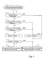
- Fig. 1 is here at the beginning of the start (step 1) as a fundamental condition for detecting the vibration behavior for a ballast track on a wheel with the query 2, a wheel acceleration required above a Radbenchungs limit (B lim ). for example, above 1 g. Then the vibration behavior of the individual wheels is checked for a specific, characteristic of a ballast track vibration behavior.
- the wheel acceleration limit value (B lim ) is exceeded, the time period between the maxima of one oscillation period is determined and it is checked in the interrogation steps 3 and 4 whether the period of the oscillations at the wheel is within a predetermined period of time that passes through an upper limit (T 1 ) (step 3) and a lower limit (T 2 ) (step 4) is defined.
- the interval defined by the upper limit (T 1 ) and the lower limit (T 2 ) is determined depending on the dynamics and vibration behavior of the driveline of the vehicle and the lane to be detected. If these conditions are met, an integrator associated with the wheel under consideration is incremented in a predetermined period of time.
- a counter assigned to the relevant wheel is incremented by 1 in each case. If this is not true, then in step 6 the counter is decremented by one. The value can thus be decremented to the value zero (0).
- a threshold COUNTER lim
- the conditions of a gravel road are detected for the wheel concerned (step 8). In the other case, if the conditions of steps 2 or 3 or 4 or 7 are not have been met, the vibration conditions for a ballast road on the wheel are not recognized (step 9).
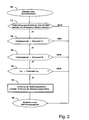
- the driving situation of a ballast lane is advantageously determined according to the flowchart shown in FIG. 2 (initial step 10).
- the determined vibration behavior of the individual wheels is compared with each other. If the vibration behavior for a gravel roadway was detected on at least two wheels (step 11), the traction slip is within a predetermined range, ie below a first limit value (S 1 ), for example 50 km / h (step 12) and above a second limit value ( S 2 ), for example, 0 km / h (step 13), the query proceeds to step 14.
- step 14 it is asked whether the vehicle reference speed (V ref ) below a speed threshold (V lim ), for example below 80 km / h , lies. If this is the case, the driving situation of a gravel road is considered to be detected and a corresponding control function of the vehicle control can take place. This may be, for example, an increase in the engine control threshold and / or the brake control threshold (step 15). In the other cases, if the conditions of the queries in steps 11 or 12 or 13 or 14 are not met, a return to the main program of the control, such as an ASR control (step 16).
- V ref vehicle reference speed
- V lim speed threshold
- Fig. 3 the block diagram of a circuit arrangement is shown, which shows by way of example the essential electrical / electronic components of an embodiment for detecting a gravel roadway.
- the detection circuit (20) is associated with a detection circuit (21) for detecting the vibration behavior of the individual wheels whose output (22) is connected to an input (23) of an evaluation circuit (24) for evaluating the detected vibration behavior.
- the detection circuit (20) has an integrator (25) and a signal generator (26) for generating a signal when, with the aid of the evaluation by the evaluation circuit (23) over a predetermined by the integrator (25) a certain time for a Ballast track typical vibration behavior of the wheels is detected.
- the detection circuit (20) is further associated with a detection circuit (27) for determining a vehicle reference speed (V ref ) based on measured values.
- An output (28) of the detection circuit (27) is connected to an input (29) of a first comparator (30), which serves the determined vehicle reference speed (V ref ) with a predetermined limit value (V lim ) and which first comparator (30) via an output (31) to an input (32) of the evaluation circuit (23) is connected, which compares the detected vibration behavior of the individual wheels, in particular the period of an oscillation with predetermined limit values (T 1 , T 2 ).
- the detection circuit (20) has a second comparator (33) for comparing the wheel acceleration with a wheel acceleration limit (B lim ), a third comparator (34) for comparing the vibration behavior of the individual wheels with each other, and a fourth comparator (35) for comparison the drive slip of the wheels with a predetermined limit (S 1 , S 2 ).
- the signal generator (26) is connected via an output (36) to an input (37) of a device (38), with the help of an appropriate signal for the detected driving situation of a gravel roadway an intervention in the brake control and / or engine control is vor spiritbar.
Landscapes
- Engineering & Computer Science (AREA)
- Transportation (AREA)
- Mechanical Engineering (AREA)
- Chemical & Material Sciences (AREA)
- Combustion & Propulsion (AREA)
- Regulating Braking Force (AREA)
- Control Of Vehicle Engines Or Engines For Specific Uses (AREA)
Applications Claiming Priority (5)
| Application Number | Priority Date | Filing Date | Title |
|---|---|---|---|
| DE19933387 | 1999-07-21 | ||
| DE19933387 | 1999-07-21 | ||
| DE10020215 | 2000-04-25 | ||
| DE10020215A DE10020215A1 (de) | 1999-07-21 | 2000-04-25 | Verfahren und Schaltungsanordnung zur Fahrzeugregelung |
| PCT/EP2000/006955 WO2001007306A1 (de) | 1999-07-21 | 2000-07-20 | Verfahren und schaltungsanordnung zur fahrzeugregelung |
Publications (2)
| Publication Number | Publication Date |
|---|---|
| EP1202889A1 EP1202889A1 (de) | 2002-05-08 |
| EP1202889B1 true EP1202889B1 (de) | 2007-09-26 |
Family
ID=26005454
Family Applications (1)
| Application Number | Title | Priority Date | Filing Date |
|---|---|---|---|
| EP00951412A Expired - Lifetime EP1202889B1 (de) | 1999-07-21 | 2000-07-20 | Verfahren und schaltungsanordnung zur fahrzeugregelung |
Country Status (4)
| Country | Link |
|---|---|
| EP (1) | EP1202889B1 (enExample) |
| JP (1) | JP2003505293A (enExample) |
| DE (1) | DE50014677D1 (enExample) |
| WO (1) | WO2001007306A1 (enExample) |
Families Citing this family (1)
| Publication number | Priority date | Publication date | Assignee | Title |
|---|---|---|---|---|
| JP4229965B2 (ja) | 2006-11-14 | 2009-02-25 | 横浜ゴム株式会社 | ブレーキ制御方法およびブレーキ制御装置 |
Family Cites Families (5)
| Publication number | Priority date | Publication date | Assignee | Title |
|---|---|---|---|---|
| DE4239177A1 (de) * | 1992-11-21 | 1994-05-26 | Teves Gmbh Alfred | Verfahren zur besseren Anpassung einer Blockierschutzregelung an den jeweiligen Straßenzustand |
| DE4418769C1 (de) * | 1994-05-28 | 1995-08-24 | Daimler Benz Ag | Verfahren zur Dämpfung von Regelschwingungen eines mittels Lowrad-Bremseneingriffen traktionsregelnden Systems in einem Kraftfahrzeug |
| US5615935A (en) * | 1995-09-21 | 1997-04-01 | Robert Bosch Gmbh | ABS control for a four wheel drive vehicle experiencing axle oscillations |
| DE19548564A1 (de) * | 1995-12-23 | 1997-06-26 | Bosch Gmbh Robert | Verfahren und Vorrichtung zur Antriebsschlupfregelung |
| DE19705948A1 (de) * | 1997-02-17 | 1998-08-20 | Itt Mfg Enterprises Inc | Verfahren zum Dämpfen von Antriebsstrangschwingungen |
-
2000
- 2000-07-20 DE DE50014677T patent/DE50014677D1/de not_active Expired - Lifetime
- 2000-07-20 JP JP2001512411A patent/JP2003505293A/ja not_active Withdrawn
- 2000-07-20 WO PCT/EP2000/006955 patent/WO2001007306A1/de not_active Ceased
- 2000-07-20 EP EP00951412A patent/EP1202889B1/de not_active Expired - Lifetime
Also Published As
| Publication number | Publication date |
|---|---|
| WO2001007306A1 (de) | 2001-02-01 |
| EP1202889A1 (de) | 2002-05-08 |
| JP2003505293A (ja) | 2003-02-12 |
| DE50014677D1 (de) | 2007-11-08 |
Similar Documents
| Publication | Publication Date | Title |
|---|---|---|
| EP1107894B1 (de) | Verfahren und vorrichtung zur erkennung einer pendelbewegung eines fahrzeugs | |
| EP1562811B1 (de) | Verfahren und einrichtung zum stabilisieren eines gespanns | |
| EP0765787B1 (de) | Verfahren zur Verbesserung der Querstabilität bei Kraftfahrzeugen | |
| DE19949286B4 (de) | Vorrichtung und Verfahren zur Regelung wenigstens einer Fahrzeugbewegungsgrösse | |
| EP0367962A1 (de) | Verfahren und Vorrichtung zur Steuerung von Sperrdifferentialen | |
| EP1005423A1 (de) | Verfahren und vorrichtung zur bestimmung der referenz-geschwindigkeit in einem kraftfahrzeug | |
| WO2007096110A1 (de) | Verfahren und vorrichtung zur regelung des antriebsschlupfes angetriebener räder eines fahrzeugs mit der motordrehzahl als stellgrösse | |
| DE19837521B4 (de) | Verfahren und Vorrichtung zur Antriebsschlupfregelung | |
| DE19834167B4 (de) | Verfahren und Vorrichtung zur Anpassung der Bremsleistung an momentane Rad-Fahrbahn-Kraftschluß-Bedingungen | |
| EP1163135A1 (de) | Verfahren zur fahrzeugregelung | |
| EP0927119A1 (de) | Verfahren und vorrichtung zur ermittlung einer die fahrzeuggeschwindigkeit beschreibenden grösse | |
| EP0859712A1 (de) | Verfahren und vorrichtung zur regelung einer die fahrzeugbewegung repräsentierenden bewegungsgrösse | |
| EP1202889B1 (de) | Verfahren und schaltungsanordnung zur fahrzeugregelung | |
| DE102019202803A1 (de) | Verfahren und System zur Ermittlung mindestens einer Reifenkennlinie für zumindest einen Reifen eines Kraftfahrzeugs | |
| EP1070623B1 (de) | Verfahren zur Antriebsschlupfregelung | |
| DE19859964C2 (de) | Verfahren und Vorrichtung zur Steuerung der Bremswirkung an wenigstens einer Radbremse eines vierradangetriebenen Kraftfahrzeugs | |
| DE10020215A1 (de) | Verfahren und Schaltungsanordnung zur Fahrzeugregelung | |
| EP1419946B1 (de) | ABS-Regellogik mit Gelände-Modul | |
| EP0876272A1 (de) | Verfahren zur verbesserung des regelverhaltens eines bremsdruckregelungssystems | |
| EP1472124A1 (de) | Verfahren zur traktionsregelung schlupfbehafteter räder wenigstens einer antriebsachse | |
| DE10107454B4 (de) | Verfahren zur Verbesserung des Regelverhaltens eines Radschlupfregelungssystems | |
| EP1515881A1 (de) | Verfahren und vorrichtung zur einstellung einer gewünschten längsverzögerung oder längsbeschleunigung | |
| DE19933085A1 (de) | Verfahren und Vorrichtung zur Antriebsschlupfregelung | |
| EP1286848B1 (de) | Verfahren zum betreiben einer fahrzeugsantriebsvorrichtung mit kontinuierlich verstellbarem getriebe (cvt) in einer bremseingriffsbetriebsart | |
| DE10238224B4 (de) | Kurvenabhängige Motorschleppmomentenregelung |
Legal Events
| Date | Code | Title | Description |
|---|---|---|---|
| PUAI | Public reference made under article 153(3) epc to a published international application that has entered the european phase |
Free format text: ORIGINAL CODE: 0009012 |
|
| 17P | Request for examination filed |
Effective date: 20020221 |
|
| AK | Designated contracting states |
Kind code of ref document: A1 Designated state(s): AT BE CH CY DE DK ES FI FR GB GR IE IT LI LU MC NL PT SE |
|
| RBV | Designated contracting states (corrected) |
Designated state(s): DE FR |
|
| 17Q | First examination report despatched |
Effective date: 20050315 |
|
| GRAP | Despatch of communication of intention to grant a patent |
Free format text: ORIGINAL CODE: EPIDOSNIGR1 |
|
| GRAS | Grant fee paid |
Free format text: ORIGINAL CODE: EPIDOSNIGR3 |
|
| GRAA | (expected) grant |
Free format text: ORIGINAL CODE: 0009210 |
|
| AK | Designated contracting states |
Kind code of ref document: B1 Designated state(s): DE FR |
|
| REF | Corresponds to: |
Ref document number: 50014677 Country of ref document: DE Date of ref document: 20071108 Kind code of ref document: P |
|
| ET | Fr: translation filed | ||
| PLBE | No opposition filed within time limit |
Free format text: ORIGINAL CODE: 0009261 |
|
| STAA | Information on the status of an ep patent application or granted ep patent |
Free format text: STATUS: NO OPPOSITION FILED WITHIN TIME LIMIT |
|
| 26N | No opposition filed |
Effective date: 20080627 |
|
| REG | Reference to a national code |
Ref country code: FR Ref legal event code: PLFP Year of fee payment: 17 |
|
| PGFP | Annual fee paid to national office [announced via postgrant information from national office to epo] |
Ref country code: FR Payment date: 20160721 Year of fee payment: 17 |
|
| REG | Reference to a national code |
Ref country code: FR Ref legal event code: ST Effective date: 20180330 |
|
| PG25 | Lapsed in a contracting state [announced via postgrant information from national office to epo] |
Ref country code: FR Free format text: LAPSE BECAUSE OF NON-PAYMENT OF DUE FEES Effective date: 20170731 |
|
| PGFP | Annual fee paid to national office [announced via postgrant information from national office to epo] |
Ref country code: DE Payment date: 20180731 Year of fee payment: 19 |
|
| REG | Reference to a national code |
Ref country code: DE Ref legal event code: R119 Ref document number: 50014677 Country of ref document: DE |
|
| PG25 | Lapsed in a contracting state [announced via postgrant information from national office to epo] |
Ref country code: DE Free format text: LAPSE BECAUSE OF NON-PAYMENT OF DUE FEES Effective date: 20200201 |