EP1202871B1 - Dossier de siège de véhicule à dispositif de protection intégré - Google Patents
Dossier de siège de véhicule à dispositif de protection intégré Download PDFInfo
- Publication number
- EP1202871B1 EP1202871B1 EP00958458A EP00958458A EP1202871B1 EP 1202871 B1 EP1202871 B1 EP 1202871B1 EP 00958458 A EP00958458 A EP 00958458A EP 00958458 A EP00958458 A EP 00958458A EP 1202871 B1 EP1202871 B1 EP 1202871B1
- Authority
- EP
- European Patent Office
- Prior art keywords
- backrest part
- backrest
- normal use
- upper backrest
- use position
- Prior art date
- Legal status (The legal status is an assumption and is not a legal conclusion. Google has not performed a legal analysis and makes no representation as to the accuracy of the status listed.)
- Expired - Lifetime
Links
Images


Classifications
-
- B—PERFORMING OPERATIONS; TRANSPORTING
- B60—VEHICLES IN GENERAL
- B60N—SEATS SPECIALLY ADAPTED FOR VEHICLES; VEHICLE PASSENGER ACCOMMODATION NOT OTHERWISE PROVIDED FOR
- B60N2/00—Seats specially adapted for vehicles; Arrangement or mounting of seats in vehicles
- B60N2/80—Head-rests
- B60N2/806—Head-rests movable or adjustable
- B60N2/838—Tiltable
- B60N2/841—Tiltable characterised by their locking devices
- B60N2/847—Tiltable characterised by their locking devices with stepwise positioning
-
- B—PERFORMING OPERATIONS; TRANSPORTING
- B60—VEHICLES IN GENERAL
- B60N—SEATS SPECIALLY ADAPTED FOR VEHICLES; VEHICLE PASSENGER ACCOMMODATION NOT OTHERWISE PROVIDED FOR
- B60N2/00—Seats specially adapted for vehicles; Arrangement or mounting of seats in vehicles
- B60N2/80—Head-rests
- B60N2/806—Head-rests movable or adjustable
- B60N2/809—Head-rests movable or adjustable vertically slidable
-
- B—PERFORMING OPERATIONS; TRANSPORTING
- B60—VEHICLES IN GENERAL
- B60N—SEATS SPECIALLY ADAPTED FOR VEHICLES; VEHICLE PASSENGER ACCOMMODATION NOT OTHERWISE PROVIDED FOR
- B60N2/00—Seats specially adapted for vehicles; Arrangement or mounting of seats in vehicles
- B60N2/80—Head-rests
- B60N2/806—Head-rests movable or adjustable
- B60N2/838—Tiltable
- B60N2/853—Tiltable characterised by their adjusting mechanisms, e.g. electric motors
-
- B—PERFORMING OPERATIONS; TRANSPORTING
- B60—VEHICLES IN GENERAL
- B60N—SEATS SPECIALLY ADAPTED FOR VEHICLES; VEHICLE PASSENGER ACCOMMODATION NOT OTHERWISE PROVIDED FOR
- B60N2/00—Seats specially adapted for vehicles; Arrangement or mounting of seats in vehicles
- B60N2/80—Head-rests
- B60N2/806—Head-rests movable or adjustable
- B60N2/838—Tiltable
- B60N2/856—Tiltable movable to an inoperative or stowed position
-
- B—PERFORMING OPERATIONS; TRANSPORTING
- B60—VEHICLES IN GENERAL
- B60N—SEATS SPECIALLY ADAPTED FOR VEHICLES; VEHICLE PASSENGER ACCOMMODATION NOT OTHERWISE PROVIDED FOR
- B60N2/00—Seats specially adapted for vehicles; Arrangement or mounting of seats in vehicles
- B60N2/80—Head-rests
- B60N2/888—Head-rests with arrangements for protecting against abnormal g-forces, e.g. by displacement of the head-rest
Definitions
- the present invention relates to a backrest for a vehicle seat with a integrated protective device against accidental injuries to a seat user in the event of a rear impact, especially against cervical spine syndrome or whiplash, with a lower backrest part connected to a seat part and with a upper backrest part, which is in the backrest transverse to the vehicle's longitudinal axis extending axis relative to the lower backrest part from a normal use position out in a swivel direction pointing in the direction of travel by a torque is pivotable through an angular range into a safety position, the Protective device a device for generating the torque means Detection of a rear impact and locking means for fixing the upper part of the backrest in the normal position of use (see, for example, DE 19 743 339 A1).
- the disadvantage here is that the relative movement of the headrest only in the Backrest thrown into the occupants.
- the upper part of the backrest can only be accelerated in the swivel direction by a value that is maximum is equal to the acceleration value that the vehicle seat experiences as a result of the impact.
- the impact of the occupant's head can be intensified and also an ascent of the occupant (vertical movement in the seat upwards) not be avoided.
- Mechanisms opposed by moving the body of the vehicle occupant the direction of travel into the backrest are not shown desired protective effect. They prove to be a particular disadvantage different size dimensions and the associated weights of the Vehicle user. Based on this, there is no guarantee that the triggering device protective device is taken and becomes effective. Another The uncertainty factor is the sluggish reaction of the previously known ones Mechanisms.
- the design of the upholstery also plays an important role Backrest; this should be as thin as possible in the area of the triggering device. This would in turn lead to an undesirable deterioration in the comfort of the upholstery to lead.
- a safe triggering of the protective device is independent on the constitution of the vehicle occupant at a minimum acceleration, which e.g. can be measured at the vehicle seat.
- the measured acceleration value is in a small car at a much lower approach speed achieved than is the case with a sedan with great damping Crumple zone or in a truck.
- the proposed protective device on the one hand has a device that is independent of occupancy of the vehicle seat that acts on the upper backrest part in the pivoting direction Generates torque, on the other hand it includes means for detecting a rear impact, that in operative connection with the torque-generating device stand that the device is activated in the event of a rear impact and the Swiveling movement is initiated.
- locking means are also available Fixation of the upper backrest part in the normal use position and locking device to fix the upper backrest against a backward movement from the safety position provided in the normal use position.
- the present invention has for its object with little design expensive means to create a backrest of the type mentioned, the Protection device an improved protection against injury to the respective seat user guaranteed, in particular by an improved interception and damping when hitting the head and the upper body of those on the seat Person on the headrest or the backrest.
- the Protection device in the Normal use position and additionally in the safety position an effective, but the locking process does not hinder the triggering process.
- the object underlying the invention is achieved by a backrest solved type mentioned, which is characterized in that the device for generating the torque from a force acting independently of an occupancy of the vehicle seat Energy storage, the means for detecting a rear impact by a Vehicle crash sensor, such as an acceleration sensor, and the locking means are formed from a lever system, the vehicle crash sensor being so in Active connection with the power or energy storage and with which the locking means to fix the upper backrest-forming lever system is that in the case of Rear impact the fixation of the upper backrest part in the normal use position canceled, the power and energy storage activated and thereby the pivoting movement is initiated.
- the pivoting of the upper backrest part preferably so quickly run that the upper backrest part is in the safety position before one head movement caused by the rear impact of the seat user.
- the upper backrest part lies directly on the body of the seat user so that it is advantageous despite the impact on it by the impact Acceleration no longer backwards, against the direction of travel of the vehicle, can move freely and suffer accidental damage.
- Protective device is particularly advantageous if one in or on the upper backrest part Headrest is attached. It is convenient to use the headrest, which is usually used Adjusting the height position is carried out on handrails, in the backrest Height of the shoulder area around an axis transverse to the vehicle axis tiltable storage. For this purpose e.g. an upper cross member of the backrest in the upper sections of the side rails of the backrest by means of a swivel bearing be attached.
- the upper backrest part can also be designed in this way be that it takes on the function of a headrest.
- a preloaded torsion spring has been found to be particularly advantageous proven because this has a very low self-acceleration and therefore in Compared to tension or compression springs, less installation space with the same effect is required.
- the lever system of the locking means for fixing the upper backrest part in the Normal use position can preferably consist of at least two cooperating levers.
- a first lever - hereinafter referred to as a jack - can opposite the pivotable cross member biased by the torsion spring support a fixed counter bearing, while a second lever, which is further Locking lever is called, acts as locking the pawl.
- the locking lever In the event of a rear impact the locking lever is pivoted in such a way that it releases the locking of the pawl.
- the locking lever can be released with only a very small actuating force can be realized, whereby a very fast lever movement and thus a quick Unlocking the pawl is possible.
- the locking lever can preferably be actuated by an electromagnet take place, its pulse from the vehicle crash sensor, like one Acceleration sensor, which receives as a means of detecting the rear impact is used.
- this can be activated by reactivating the Means that the torque acting in the pivoting direction on the upper backrest part generated (e.g. by tensioning the torsion spring), back to their starting position brought, this process for safety reasons only in a workshop, in which the seat function can also be checked after a crash is.
- the Means that the torque acting in the pivoting direction on the upper backrest part generated e.g. by tensioning the torsion spring
- a vehicle seat 1 consists of a backrest 2 according to the invention and a seat part 3.
- the backrest 2 is a Protective device integrated to protect the respective person against accidental injuries, especially against cervical spine syndrome or Whiplash in the event of a rear impact.
- the backrest 2 has a lower backrest part 4 connected to the seat part 3 and an upper backrest part 5, about an axis X-X extending in the backrest 2 transversely to the longitudinal axis of the vehicle relative to the lower backrest part 4 from a normal position of use (in Fig. 1 with Solid line drawn) out in a direction of rotation S pointing in the direction of travel F. by a torque acting in the swivel direction S around an angular range in a safety position (drawn with a dash-dotted line in Fig. 1) pivotable is.
- the protective device on the one hand has a device 6 which regardless of an occupancy of the vehicle seat 2 in the swivel direction S.
- the upper backrest part 5 acting torque (arrow M in Fig. 1) generates, on the other hand it has means 7 for detecting a rear-end collision.
- Both the Torque generating device 6 as well as the detection means 7 can be different. Therefore, these parts of the invention Backrest 2 in Fig. 1 only drawn schematically (as a box).
- the torque generating device 6 can, for example, advantageously by a Power or energy storage, in particular by a prestressed spring element or several prestressed spring elements.
- a Power or energy storage in particular by a prestressed spring element or several prestressed spring elements.
- Torque generating device is Torque generating device than in the transverse to the longitudinal axis of the vehicle extending pivot axis X-X of the upper backrest part 5 lying, leaf-shaped Torsion spring (torsion spring 6a) formed, which is advantageously a very low Has self-acceleration and with the same effect compared to train or Compression spring requires little installation space (cf. in particular Fig. 3).
- the means 7 for detecting the rear-end collision can advantageously be formed by a vehicle crash sensor, such as an acceleration sensor.
- the vehicle crash sensor can be set such that it responds at an acceleration a of approximately 40 to 80 m / s 2 .
- the value of the acceleration at which the sensor responds depends on the type and design of a particular motor vehicle (small car / limousine with a damping crumple zone / truck).
- the detection means 7 can thus be operatively connected to the torque-generating one Device 6 stand that the device 6 in the event of a rear impact activated and the pivoting movement of the upper backrest part 5 is initiated.
- the lower backrest part 4 remains in its original (normal use) Position.
- the lower backrest part 4 and the upper backrest part 5 can preferably be used Ensuring optimal protection of the seat user in their respective, not Specified length defined to be coordinated with each other or the transverse to Vehicle longitudinal axis X-X, about which the upper backrest part 5 is pivotable is at a defined height H in the shoulder area of a seat user, preferably about 400 to 580 mm above the seat part 3.
- a headrest 8 is attached, which at one Rear impact from a comfort position (drawn in Fig. 1 with the full line) in which you Distance (A1 in FIG. 2) to the head of a seat user is approximately 80 to 120 mm, in an interception position (drawn in Fig. 1 with a dash-dotted line) is moved in the their distance (A2 in Fig. 2) to the head of a seat user is zero or almost zero.
- locking means 9 for fixing the upper backrest part 5 in the Normal use position provided.
- the fixation is indicated by arrow A in FIG. 1 illustrated.
- These locking means 9 are, as follows with reference to FIGS. 3 to 5 in further described is formed by a lever system.
- arrow B in Fig. 1st is indicated that the locking means 9, the effect of the torque-generating Can block device 6.
- the means 7 for detecting a rear-end collision are thus operatively connected (arrow U in Fig. 1) with the locking means 9 for fixing the upper backrest part 5 in the Normal position of use that in the event of an impact, the fixation A of the upper Backrest part 5 in the normal position of use and the blocking B of the torque-generating device 6 is canceled.
- FIG. 3 which is an enlarged detail of the invention shown in Fig. 2 Backrest 2 in the area of the transition from the lower backrest part 4 to the upper one Backrest part 5 shows a preferred specific embodiment for the Device 6, which in regardless of an occupancy of the vehicle seat 2 in Swing direction S generated on the upper backrest part 5 torque M for the locking means 9 designed as a lever system for fixing the upper backrest part 5 in the normal use position and for the locking means 10 (backstop) to fix the upper backrest part 5 against a backward movement from the Safety position in the normal use position.
- the locking means 9 designed as a lever system for fixing the upper backrest part 5 in the normal use position and for the locking means 10 (backstop) to fix the upper backrest part 5 against a backward movement from the Safety position in the normal use position.
- the torque-generating device 6 in FIG. 3 is, as already mentioned, as a prestressed spring element - and that as a stored in the upper backrest part 5 leaf-shaped torsion spring 6a formed.
- a torsion spring 6a can advantageously very high actuating forces or a very high torque M are generated be a pivoting of the upper backrest part 5 in the millisecond range enable.
- the spring element it has proven to be advantageous if this has a falling characteristic curve which, in order to generate a strong acceleration high initial force, but has only a very low final force. This carries especially the fact that due to its location in the vehicle the upper backrest part 5 experiences an acceleration due to the crash, which counteracts the effect of the spring element.
- the torque generating device 6 is designed such that in the case of its Activation of the upper backrest part 5 in the pivoting direction S by a larger amount accelerates than it is a measured or preferably an empirically determined one is the average amount of acceleration a that the vehicle seat 2 through the rear impact learns what the spring characteristic (thickness and material of the torsion spring 6a) can be adjusted.
- the holding rods 8a, 8b load-bearing cross member 5a of the backrest 2 in the upper, the lower backrest part 4 protruding respective fastening sections 4 a at two with the lower back part 4 firmly connected side rails 4b about the axis X-X, in which the torsion spring 6a lies, pivoted (swivel direction S).
- the torsion spring 6a itself is at its ends Clamped laterally in the fastening sections 4a and approximately in the middle over one Holding part 6b firmly connected to the cross member 5a. So in the - in Fig. 4 exclusively and shown in Fig. 5 as a position - normal use position biased by a rotation against the designated pivoting direction S. become.
- a locking means 9 for fixing the upper backrest part 5 in the normal position of use there is a lever system provided by two (not closer designated) side walls of the pocket-shaped holding part in particular 6b is worn and that acts as a positive or non-positive lock.
- a first in particular one-armed lever (pawl 9a) is laterally in bearings 9c Holding part 6b mounted, the bearing axis Y-Y parallel to the axis of rotation X-X of upper backrest part 5, and supports the biased by the torsion spring 6a pivotable cross member 5a relative to a fixed counter bearing 4c.
- the Counter bearing 4c is located at the upper end of another with the lower back part 4 connected, protruding into the pocket-like holding part 6b Support part 4d and is by a stop surface for approximately at the free end of the lever arranged nose 9d of the pawl 9a formed. In a locked position of the pawl 9a the nose 9d on the counter bearing 4c.
- the second, in particular two-armed lever (locking lever 9b) is used for Locking the pawl 9a in its locked position. It is laterally in bearings 9e of the Holding part 6b mounted, the bearing axis Z-Z in turn parallel to the axis of rotation X-X of the upper backrest part 5, and engages in its locked position with a locking lug 9f so positively into the pawl 9a that it does not come out of its Lock position can move out.
- the representations in FIGS. 4 and 5 each show the locking positions of pawl 9a and locking lever 9b.
- the locking lever 9b When the need arises (rear-end collision), the locking lever 9b is around his Bearing axis Z-Z - according to the representations in Fig. 4 and 5 - pivoted clockwise - wherein the positive engagement of the locking lug 9f in the pawl 9a canceled and the pawl 9a for a pivoting movement about its axis Y-Y (according to the representations in Fig. 4 and 5 - also clockwise) is released.
- the locking lever 9b can be triggered with only a very small amount at one end of the lever 9g attacking operating force and e.g. with the advantage of a (not shown) Electromagnet caused its switching pulse from a Sensor (as means 7 for detecting the rear impact) receives.
- the means 7 for detecting the rear impact could - as an alternative to Sensor training - also be formed by a mechanical control system, which has mechanical parts which - accelerated by the effect of the rear impact - the locking lever 9b out of engagement, i.e. put in an unlocked position. This too corresponds to a direct operative connection U from the means 7 for detection the rear impact on the locking means 9.
- these locking means 10 to prevent a spring or rebound effect when the Protective device are designed so that they are not only in the normal position of use and in the safety position of the upper backrest part 5, but also enable locking in intermediate positions.
- This can - how based on the various embodiments of the Backstop becomes clear - for example by means of self-locking, form and / or non-positive - preferably clamping - acting rolling element or wedge locks or can be realized by means of a locking device.
- Embodiments of the backstop is on the way of a suitable Design of the backstop (size and number of rolling elements, at Swiveling back becomes effective increase in restricted areas, number and size of Teeth of a locking toothing, etc.) advantageously possible, a return play of upper backrest part 5 (backward movement against the pivoting direction S in the direction the normal position of use of the backrest part 5) to a maximum angular amount limit of about 1 °.
- 3 and 4 shows a design of the locking means 10 for Fixing the upper backrest part 5, in particular the cross member 5a, as a detent Ratchet mechanism.
- a carrier element 10a for at least one in the shown embodiment for two locking teeth 10b, 10c, within the pocket-shaped holding part 6b attached.
- the respective toothing 10b, 10c cooperates at least one, in the embodiment shown with two, as counter-locking elements Acting teeth 4e, 4f together on the support part 4d.
- the two Toothings 10b, 10c and the corresponding counter teeth 4e, 4f each are offset against each other, a higher security of the locking connection and a Reduction (halving) of the return play of the upper backrest part 5 reached.
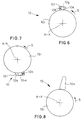
- FIG. 5 shows an embodiment of the locking means 10 for fixation of the upper backrest part 5, in particular the cross member 5a, as a rolling element locking device.
- This rolling element locking device consists of a concentric around the swivel axis X-X of the upper backrest part 5 arranged toothed ring 10d, which is arranged within a cylindrical shell 10e, and from between the teeth 10f of the ring gear 10d and between the ring gear 10d and the jacket 10e arranged rolling elements 10g.
- the torsion spring 6a is fixed to the ring gear 10d connected.
- the tooth flanks of the teeth 10f of the ring gear 10d are of this type executed that the rolling element locking device the pivoting (pivoting direction S) in the safety position of the upper backrest part 5 or in the Interception position of the headrest 8 allows, since the rolling elements 10g between the ring gear 10d and jacket 10e can roll freely while in the event of an opposite Movement a jamming of the rolling elements 10g between the ring gear 10d and the jacket 10e takes place that inhibits this return movement.
- the walls of the Recordings 10k of the jacket part 101 are designed such that the rolling element locking device the swiveling (swiveling direction S) into the safety position of the upper backrest part 5 or in the catching position of the headrest 8, because the Rolling elements 10g between the inner part 10i and the jacket part 10l against the effect the spring 10h can roll freely while in the event of an opposite movement under the additional pointing in this direction of the spring 10h The rolling elements 10g are jammed, which inhibits this return movement.
- the embodiment of the backstop shown in FIG. 7 differs from 6 that in that instead of the rolling elements 10g clamping wedges 10m be used.
- FIGS. 9 and 10 show two views of an upper part 5 of one another preferred embodiment of a backrest 2 according to the invention
- this embodiment includes the lever system of the locking means 9 for fixing A of upper backrest part 5 in the normal use position with the upper one Backrest part 5, in particular via a holder 11 with the cross member 5a of the backrest part 5, and connected to the torque generating device 6 Safety lever 9h.
- this is in particular as an um the pivot axis X-X of the upper backrest part 5 pivotable angle lever and is in a locking position shown in FIGS. 9 and 10 by a Locking bolt 9i secured.
- the locking pin 9i reaches through in the locking position Opening 9k in one angle leg of the safety lever 9h while the other Angle leg is connected to the torsion spring 6a. From the opening 9k Locking pin 9i in the event of a crash to release the torque-generating device 6 - specifically the torsion spring 6a - be moved out.
- the means 7 for detecting the rear-end collision are operatively connected in this way U with the locking means 9 for fixing A of the upper backrest part 5 in the Normal use position - in the case shown with the locking pin 9i -, and Locking means 9 - specifically the locking pin 9i and the locking lever 9h - stand thus in operative connection B with the torque-generating device 6 (Torsion spring 6a) that in the event of an impact release of the torque-generating Device 6 is initiated pyrotechnically by the locking means 9, i.e. preferably by means of an ignition cartridge.
- the pyrotechnic Device 12 can - as shown - in the holder 11 for the locking pin 9i be arranged.
- FIGS. 9 and 10 differs from a special backstop 13 provided, via which the locking lever 9h is connected to the torsion spring 6a.
- This backstop 13 serves as an assembly aid and blocks pivoting of the upper backrest part 5 in the direction S from its normal position of use in its Safety position, however, allows pivoting in the opposite direction to.
- the backstop 13 can be a self-locking, positive and / or non-positive - preferably clamping - acting rolling element or wedge lock or as Locking device can be designed such that it is also in between the safety position and the normal use position of the upper backrest part (5) lying positions enables a lock.
- the backstop 13 can as well be carried out as the locking means 10 described above for fixing K of the upper backrest against a backward movement from the safety position into the Normal use position, only that it works in the opposite direction.
- the Backstop 13 can advantageously be achieved to facilitate assembly, by first, for example, the locking pin 9i in the opening 9k of the Safety lever 9h is introduced, which is preferably in the form of an elongated hole can be formed, and then by means of a tool, the torsion spring 6a (counter the direction S) is tensioned, the backstop 13 this tensioning allows, however, an unwanted snap back (relaxation) of the torsion spring 6a prevented. In the event of a crash, however, such relaxation of the torsion spring 6a is possible, there after removing the locking pin 9i of the backstop on the torsion spring 6a held locking lever 9h can be moved.
- the invention is not limited to the illustrated embodiments are limited. This could be the case, for example Lever system other than shown or as described and executed be arranged elsewhere. As for the graphic representation, so are 6 to 8 partially shown schematically. With regard to other possible Details of the backrest 2 according to the invention and a method that can be implemented therewith to prevent accident-related injuries to a seat user to the German patent application 199 38 904.7 mentioned at the beginning directed.
Claims (22)
- Dossier (2) pour un siège de véhicule (1) comprenant un dispositif de protection intégré (4, 5, 6, 7, 8, 9, 10, 11, 12, 13) contre des blessures d'un utilisateur du siège provoquées lors d'un accident dans le cas d'un choc par l'arrière, en particulier contre le syndrome des vertèbres cervicales ou d'un syndrome de whiplash, avec une partie de dossier inférieure (4) connectée à une partie de siège (3) et avec une partie de dossier supérieure (5) qui peut pivoter autour d'un axe (X-X) s'étendant dans le dossier (2) transversalement à l'axe longitudinal du véhicule par rapport à la partie de dossier inférieure (4) depuis une position d'utilisation normale dans une direction de pivotement (S) tournée dans la direction de conduite (F) par un couple (M) agissant dans la direction de pivotement autour d'une région coudée dans une position de sécurité, le dispositif de protection (4, 5, 6, 7, 8, 9, 10, 11, 12, 13) présentant un dispositif (6) pour produire le couple (M), des moyens (7) pour détecter un choc par l'arrière et des moyens de blocage (9) pour fixer (A) la partie de dossier supérieure (5) dans la position d'utilisation normale,
caractérisé en ce que le dispositif (6) pour produire le couple (M) est formé par un accumulateur de force ou d'énergie agissant indépendamment d'une occupation du siège (2) du véhicule, les moyens (7) pour la détection d'un choc par l'arrière sont formés par un capteur de collision du véhicule, comme un capteur d'accélération, et les moyens de blocage (9) sont formés par un système de levier, le capteur de collision de véhicule étant en liaison coopérante (U, B) avec l'accumulateur de force ou d'énergie et avec le système de levier formant les moyens de blocage (9) pour la fixation () de la partie de dossier supérieure (5) de telle sorte que dans le cas d'un choc par l'arrière, la fixation (A) de la partie de dossier supérieure (5) soit soulevée dans la position d'utilisation normale, que l'accumulateur de force et d'énergie soit activé et que de ce fait le mouvement de pivotement soit amorcé. - Dossier selon la revendication 1,
caractérisé en ce que dans ou sur la partie de dossier supérieur (5) est fixé un appuie-tête (8), qui dans le cas d'un choc par l'arrière se déplace depuis une position de confort, dans laquelle sa distance (A1) à la tête d'un utilisateur du siège mesure environ 40 à 110 mm, dans une position de soutien dans laquelle sa distance (A2) à la tête d'un utilisateur du siège est nulle ou pratiquement nulle. - Dossier selon la revendication 1 ou 2,
caractérisé en ce que le dispositif (6) produisant un couple est formé par un élément à ressort précontraint ou par plusieurs éléments à ressort précontraints. - Dossier selon la revendication 3,
caractérisé en ce que l'élément à ressort est formé par un ressort de torsion (6a) disposé de préférence dans l'axe de pivotement (X-X). - Dossier selon la revendication 3 ou 4,
caractérisé en ce que les moyens (7) pour détecter un choc par l'arrière sont en liaison coopérante (U) de telle sorte avec les moyens de blocage (9) pour la fixation (A) de la partie de dossier supérieure (5) dans la position d'utilisation normale, et les moyens de blocage (9) sont en liaison coopérante (B) de telle sorte avec le dispositif (6) produisant un couple, que dans le cas de la collision, l'élément à ressort précontraint, en particulier le ressort de torsion (6a) soit libéré par les moyens de blocage (9). - Dossier selon l'une quelconque des revendications 1 à 5,
caractérisé par des moyens de blocage (10) pour la fixation (K) de la partie de dossier supérieure (5) contre un mouvement de recul depuis la position de sécurité dans la position d'utilisation normale. - Dossier selon l'une quelconque des revendications 1 à 6,
caractérisé en ce que le système de levier des moyens de blocage (9) pour la fixation (B) de la partie de dossier supérieure (5) dans la position d'utilisation normale est formé par au moins deux leviers coopérants (9a, 9b). - Dossier selon l'une quelconque des revendications 1 à 7,
caractérisé en ce que le système de levier des moyens de blocage (9) pour la fixation (A) de la partie de dossier supérieure (5) dans la position d'utilisation normale comprend un levier de fixation (9h) connecté fixement à la partie de dossier supérieure (5), en particulier par le biais d'une fixation (11) à un longeron transversal (5a) de la partie de dossier (5), et au dispositif (6) produisant le couple, en particulier un levier coudé pouvant pivoter autour de l'axe de pivotement (X-X) de la partie de dossier supérieure (5), qui est fixé dans une position de blocage par un boulon de blocage (9i). - Dossier selon la revendication 8,
caractérisé en ce que le boulon de blocage (9i) dans la position de blocage vient en prise à travers une ouverture (9k) notamment de type trou oblong du levier de fixation (9h), depuis laquelle il est ressorti pour libérer le dispositif (6) produisant le couple. - Dossier selon la revendication 8 ou 9,
caractérisé en ce que le levier de fixation (9h) est connecté au ressort de torsion (6a) par le biais d'une butée de retour (13) qui bloque un pivotement de la partie de dossier supérieure (5) dans la direction (S) depuis sa position d'utilisation normale dans sa position de sécurité, mais l'autorise toutefois dans la direction opposée. - Dossier selon la revendication 10,
caractérisé en ce que la butée de retour (13) est réalisée en tant que butée à éléments roulants ou butée à coin ou en tant que dispositif d'encliquetage agissant de manière autobloquante, par engagement positif et/ou par force, de préférence par serrage, de telle sorte qu'elle permette également un blocage dans des positions se trouvant entre la position de sécurité et la position d'utilisation normale de la partie de dossier supérieure (5). - Dossier selon l'une quelconque des revendications 1 à 7,
caractérisé en ce que le système de levier est formé à partir d'un cliquet (9a) monté pivotant dans la partie de dossier supérieure (5), en particulier dans un longeron transversal (5a) de la partie de dossier (5), qui s'appuie dans une position de blocage contre un palier conjugué (4c) fixé par rapport à la partie de dossier supérieure (5) et à partir d'un levier de blocage (9b) monté pivotant, qui vient en prise dans une position de blocage dans le cliquet (9a), et qui libère le cliquet (9a) dans une position de libération. - Dossier selon l'une quelconque des revendications 1 à 12,
caractérisé en ce que le système de levier est monté dans les parois latérales d'une partie de fixation (6b) de type poche disposée dans la partie de dossier supérieure (5). - Dossier selon la revendication 12 ou 13,
caractérisé en ce que le palier conjugué (4c) est disposé sur une extrémité supérieure d'une partie de support (4d) connectée fixement à l'autre extrémité à la partie de dossier inférieure (4), saillant de préférence dans la partie de fixation (6b) de type poche, et est formé par une surface de butée pour un nez (9d) du cliquet (9a) disposé approximativement à une extrémité libre de levier. - Dossier selon l'une quelconque des revendications 12 à 14,
caractérisé en ce qu'un mouvement du levier de blocage (9b) de sa position de blocage dans sa position de libération est effectué au moyen d'un électroaimant qui obtient son impulsion de commutation d'un capteur servant de moyen (7) pour détecter le choc par l'arrière. - Dossier selon l'une quelconque des revendications 6 à 15,
caractérisé en ce que les moyens de blocage (10) pour la fixation (K) de la partie de dossier supérieure (5) contre un mouvement de recul hors de la position de sécurité dans la position d'utilisation normale sont réalisés à chaque fois sous la forme d'une butée à éléments roulants ou butée à coin ou en tant que dispositif d'encliquetage agissant de manière autobloquante, par engagement positif et/ou par force, de préférence par serrage, les moyens de blocage (10) permettant de préférence également dans des positions se trouvant entre la position de sécurité et la position d'utilisation normale de la partie de dossier supérieure (5) un blocage contre un mouvement de recul. - Dossier selon l'une quelconque des revendications 6 à 16,
caractérisé en ce que les moyens de blocage (10) pour la fixation (K) de la partie de dossier supérieure (5) contre un mouvement de recul hors de la position de sécurité dans la position d'utilisation normale sont réalisés à chaque fois sous la forme d'un mécanisme à cliquet encliquetable avec au moins une, de préférence deux, dentures d'encliquetage (10b, 10c) fixées en particulier à l'intérieur de la partie de fixation (6b) en forme de poche et avec au moins une, de préférence deux, dents (4e, 4f) servant d'éléments d'encliquetage conjugués, disposées en particulier sur la partie de support (4d). - Dossier selon l'une quelconque des revendications 6 à 16,
caractérisé en ce que les moyens de blocage (10) pour la fixation (K) de la partie de dossier supérieure (5) contre un mouvement de recul hors de la position de sécurité dans la position d'utilisation normale sont réalisés sous la forme de dispositif de butée à éléments roulants qui comprend une couronne dentée (10d) disposée conceritriquement autour de l'axe de pivotement (X-X) de la partie de dossier supérieur (5), qui est disposée à l'intérieur d'une enveloppe cylindrique (10e), ainsi qu'un élément roulant (10g) disposé entre les dents (10f) de la couronne dentée (10d) et entre la couronne dentée (10d) et l'enveloppe (10e). - Dossier selon l'une quelconque des revendications 6 à 16,
caractérisé en ce que les moyens de blocage (10) pour la fixation (K) de la partie de dossier supérieure (5) contre un mouvement de recul hors de la position de sécurité dans la position d'utilisation normale sont réalisés sous la forme de butée de retour, qui comprend une partie interne (10i) cylindrique disposée concentriquement autour de l'axe de pivotement (X-X) de la partie de dossier supérieure (5), qui est disposée à l'intérieur d'une partie d'enveloppe (10l) ainsi que des éléments roulants (10g) ou des coins de serrage (10m) disposés dans des logements (10k) de la partie d'enveloppe (10l). - Dossier selon l'une quelconque des revendications 6 à 16,
caractérisé en ce que les moyens de blocage (10) pour la fixation (K) de la partie de dossier supérieure (5) contre un mouvement de recul hors de la position de sécurité dans la position d'utilisation normale sont réalisés sous la forme de butée de retour, qui comprend une partie interne (10i) cylindrique avec une surface d'enveloppe lisse ou structurée pour augmenter les frottements ou pourvue d'un revêtement, et d'un corps pivotant (10n) monté de manière excentrique et venant en prise par engagement par force contre la surface d'enveloppe de la partie interne (10i). - Dossier selon l'une quelconque des revendications 6 à 16,
caractérisé en ce que les moyens de blocage (10) pour la fixation (K) de la partie de dossier supérieure (5) contre un mouvement de recul hors de la position de sécurité dans la position d'utilisation normale sont réalisés de telle sorte que les moyens de blocage (10) limitent un jeu de rappel, c'est-à-dire un mouvement de recul à l'encontre de la direction de pivotement (S) dans la direction de la position d'utilisation normale de la partie de dossier supérieure (5), à une valeur angulaire maximale d'environ 1°. - Dossier selon l'une quelconque des revendications 1 à 21,
caractérisé en ce que les moyens (7) pour détecter un choc par l'arrière sont en liaison coopérante (U) de telle sorte avec les moyens de blocage (9) pour la fixation (A) de la partie de dossier supérieure (5) dans la position d'utilisation normale et les moyens de blocage (9) sont en liaison coopérante (B) de telle sorte avec le dispositif (6) produisant le couple, que dans le cas de la collision, une libération du dispositif (6) produisant le couple s'effectue au moyen des moyens de blocage (9), en particulier par le/un levier de fixation (9h), au moyen d'un dispositif pyrotechnique (12), de préférence au moyen d'une cartouche d'allumage.
Applications Claiming Priority (5)
| Application Number | Priority Date | Filing Date | Title |
|---|---|---|---|
| DE19938904A DE19938904A1 (de) | 1999-08-17 | 1999-08-17 | Fahrzeugsitz-Rückenlehne mit integrierter Schutzeinrichtung und Verfahren zur Vorbeugung gegen unfallbedingte Verletzungen |
| DE19938904 | 1999-08-17 | ||
| DE20002171U DE20002171U1 (de) | 2000-02-08 | 2000-02-08 | Rückenlehne für einen Fahrzeugsitz mit einer integrierten Schutzeinrichtung |
| DE20002171U | 2000-02-08 | ||
| PCT/EP2000/007995 WO2001012465A1 (fr) | 1999-08-17 | 2000-08-16 | Dossier de siège de véhicule à dispositif de protection intégré |
Publications (2)
| Publication Number | Publication Date |
|---|---|
| EP1202871A1 EP1202871A1 (fr) | 2002-05-08 |
| EP1202871B1 true EP1202871B1 (fr) | 2003-11-12 |
Family
ID=26054628
Family Applications (1)
| Application Number | Title | Priority Date | Filing Date |
|---|---|---|---|
| EP00958458A Expired - Lifetime EP1202871B1 (fr) | 1999-08-17 | 2000-08-16 | Dossier de siège de véhicule à dispositif de protection intégré |
Country Status (3)
| Country | Link |
|---|---|
| EP (1) | EP1202871B1 (fr) |
| DE (1) | DE50004441D1 (fr) |
| WO (1) | WO2001012465A1 (fr) |
Cited By (1)
| Publication number | Priority date | Publication date | Assignee | Title |
|---|---|---|---|---|
| US8205941B2 (en) | 2008-07-30 | 2012-06-26 | Trw Vehicle Safety Systems Inc. | Active head restraint for a vehicle seat |
Families Citing this family (8)
| Publication number | Priority date | Publication date | Assignee | Title |
|---|---|---|---|---|
| DE19938904A1 (de) | 1999-08-17 | 2001-03-08 | Johnson Controls Gmbh | Fahrzeugsitz-Rückenlehne mit integrierter Schutzeinrichtung und Verfahren zur Vorbeugung gegen unfallbedingte Verletzungen |
| DE20107765U1 (de) | 2001-05-08 | 2002-09-19 | Johnson Controls Gmbh | Schutzeinrichtung gegen unfallbedingte Verletzungen eines Benutzers eines Fahrzeugsitzes und mechanisches System zur Detektierung eines Fahrzeugaufpralls |
| FR2824799B1 (fr) * | 2001-05-17 | 2004-10-29 | Faurecia Sieges Automobile | Siege de vehicule dote d'un dispositif de protection du cou en cas d'accident |
| DE10215054B4 (de) * | 2002-04-05 | 2007-01-18 | Keiper Gmbh & Co.Kg | Kopfstütze für einen Fahrzeugsitz |
| WO2004056606A1 (fr) | 2002-12-21 | 2004-07-08 | Keiper Gmbh & Co. Kg | Appui-tete actif en cas de choc |
| DE10325472A1 (de) | 2003-06-05 | 2004-12-30 | Keiper Gmbh & Co. Kg | Crashaktive Kopfstütze |
| DE102004035582B3 (de) | 2004-07-22 | 2006-02-02 | Keiper Gmbh & Co.Kg | Crashaktive Kopfstütze |
| WO2006089930A1 (fr) * | 2005-02-23 | 2006-08-31 | Heinz Peter | Systeme de protection pour ameliorer la securite des passagers dans un vehicule a moteur |
Family Cites Families (4)
| Publication number | Priority date | Publication date | Assignee | Title |
|---|---|---|---|---|
| SE9402877L (sv) * | 1994-08-30 | 1996-05-15 | Autosafe Automobile I Stockhol | Anordning för att motverka pisksnärtskador |
| GB2318045B (en) * | 1996-10-09 | 2000-08-09 | Delphi Automotive Systems Gmbh | Vehicle seat and headrest arrangement |
| JP2000062557A (ja) * | 1998-08-20 | 2000-02-29 | Honda Motor Co Ltd | 乗員保護装置 |
| US6196579B1 (en) * | 1998-09-24 | 2001-03-06 | Trw Vehicle Safety Systems Inc. | Rear impact occupant protection system |
-
2000
- 2000-08-16 EP EP00958458A patent/EP1202871B1/fr not_active Expired - Lifetime
- 2000-08-16 WO PCT/EP2000/007995 patent/WO2001012465A1/fr active IP Right Grant
- 2000-08-16 DE DE50004441T patent/DE50004441D1/de not_active Expired - Lifetime
Cited By (1)
| Publication number | Priority date | Publication date | Assignee | Title |
|---|---|---|---|---|
| US8205941B2 (en) | 2008-07-30 | 2012-06-26 | Trw Vehicle Safety Systems Inc. | Active head restraint for a vehicle seat |
Also Published As
| Publication number | Publication date |
|---|---|
| EP1202871A1 (fr) | 2002-05-08 |
| DE50004441D1 (de) | 2003-12-18 |
| WO2001012465A1 (fr) | 2001-02-22 |
Similar Documents
| Publication | Publication Date | Title |
|---|---|---|
| EP1077155B1 (fr) | Dossier de siège de véhicule à dispositif de protection intégré et méthode de prévention de blessures dues à des accidents | |
| EP0791501B1 (fr) | Siège de véhicule | |
| DE19643977C2 (de) | Fahrzeugsitz mit Multifunktionslehne | |
| DE19853981B4 (de) | Kraftfahrzeugsitz | |
| EP1736373B1 (fr) | Système de protection pour le capotage d'un véhicule automobile | |
| EP1608529B1 (fr) | Ensemble appui-tete pour un siege de vehicule automobile | |
| WO2010106183A1 (fr) | Système d'enrouleur de ceinture de sécurité à enclencheur | |
| DE2432956B2 (fr) | ||
| EP1202871B1 (fr) | Dossier de siège de véhicule à dispositif de protection intégré | |
| WO2008031605A1 (fr) | Dispositif de sécurité pour véhicules | |
| EP1955908B1 (fr) | Système de protection en cas de tonneaux pour véhicules automobiles comprenant un arceau orientable dirigé par capteur pouvant être placé activement | |
| WO2005084998A1 (fr) | Siege de vehicule | |
| DE102005028879B4 (de) | Überrollschutzsystem für ein Kraftfahrzeug | |
| WO2002090141A1 (fr) | Dispositif de protection servant a eviter les lesions accidentelles de l'utilisateur d'un siege de vehicule, et systeme mecanique servant a detecter un choc affectant le vehicule | |
| WO2004030981A1 (fr) | Ensemble appuie-tete pour siege de vehicule | |
| EP1736374B1 (fr) | Système d'arceau de sécurité pour un véhicule à moteur | |
| DE102017207379A1 (de) | Gurtintegralsitz als kinematisches Rückhaltesystem | |
| DE102005028966B4 (de) | Kraftfahrzeug mit einem Überrollschutzsystem an einer Fahrzeugquerwand | |
| DE102006000909B4 (de) | Überrollschutzsystem für ein Cabriolet-Fahrzeug mit gekrümmtem Überrollkörper | |
| DE102006002476B4 (de) | Überrollschutzsystem für ein Kraftfahrzeug | |
| DE102008063357A1 (de) | Fahrzeugsitz, insbesondere Nutzfahrzeugsitz | |
| DE10013325B4 (de) | Fahrzeugsitz mit einer Kopfstütze | |
| DE102006036336A1 (de) | Verfahren zum Betreiben einer Insassenrückhaltevorrichtung und Insassenrückhaltevorrichtung | |
| DE102008043019A1 (de) | Gurtsystem für ein Insassenschutzsystem in einem Fahrzeug | |
| EP2722223B9 (fr) | Système de sécurité pour un siège de véhicule |
Legal Events
| Date | Code | Title | Description |
|---|---|---|---|
| PUAI | Public reference made under article 153(3) epc to a published international application that has entered the european phase |
Free format text: ORIGINAL CODE: 0009012 |
|
| 17P | Request for examination filed |
Effective date: 20011207 |
|
| AK | Designated contracting states |
Kind code of ref document: A1 Designated state(s): AT BE CH CY DE DK ES FI FR GB GR IE IT LI LU MC NL PT SE |
|
| RTI1 | Title (correction) |
Free format text: SEAT BACK FOR A VEHICLE SEAT COMPRISING AN INTEGRATED PROTECTIVE DEVICE |
|
| RTI1 | Title (correction) |
Free format text: SEAT BACK FOR A VEHICLE SEAT COMPRISING AN INTEGRATED PROTECTIVE DEVICE |
|
| GRAH | Despatch of communication of intention to grant a patent |
Free format text: ORIGINAL CODE: EPIDOS IGRA |
|
| GRAS | Grant fee paid |
Free format text: ORIGINAL CODE: EPIDOSNIGR3 |
|
| GRAA | (expected) grant |
Free format text: ORIGINAL CODE: 0009210 |
|
| AK | Designated contracting states |
Kind code of ref document: B1 Designated state(s): DE FR GB IT |
|
| REG | Reference to a national code |
Ref country code: GB Ref legal event code: FG4D Free format text: NOT ENGLISH |
|
| REF | Corresponds to: |
Ref document number: 50004441 Country of ref document: DE Date of ref document: 20031218 Kind code of ref document: P |
|
| REG | Reference to a national code |
Ref country code: IE Ref legal event code: FG4D Free format text: GERMAN |
|
| GBT | Gb: translation of ep patent filed (gb section 77(6)(a)/1977) |
Effective date: 20040202 |
|
| REG | Reference to a national code |
Ref country code: IE Ref legal event code: FD4D |
|
| ET | Fr: translation filed | ||
| PLBE | No opposition filed within time limit |
Free format text: ORIGINAL CODE: 0009261 |
|
| STAA | Information on the status of an ep patent application or granted ep patent |
Free format text: STATUS: NO OPPOSITION FILED WITHIN TIME LIMIT |
|
| 26N | No opposition filed |
Effective date: 20040813 |
|
| PGFP | Annual fee paid to national office [announced via postgrant information from national office to epo] |
Ref country code: FR Payment date: 20050711 Year of fee payment: 6 |
|
| PGFP | Annual fee paid to national office [announced via postgrant information from national office to epo] |
Ref country code: GB Payment date: 20050713 Year of fee payment: 6 |
|
| PGFP | Annual fee paid to national office [announced via postgrant information from national office to epo] |
Ref country code: IT Payment date: 20060831 Year of fee payment: 7 |
|
| GBPC | Gb: european patent ceased through non-payment of renewal fee |
Effective date: 20060816 |
|
| REG | Reference to a national code |
Ref country code: FR Ref legal event code: ST Effective date: 20070430 |
|
| PG25 | Lapsed in a contracting state [announced via postgrant information from national office to epo] |
Ref country code: GB Free format text: LAPSE BECAUSE OF NON-PAYMENT OF DUE FEES Effective date: 20060816 |
|
| PG25 | Lapsed in a contracting state [announced via postgrant information from national office to epo] |
Ref country code: FR Free format text: LAPSE BECAUSE OF NON-PAYMENT OF DUE FEES Effective date: 20060831 |
|
| PG25 | Lapsed in a contracting state [announced via postgrant information from national office to epo] |
Ref country code: IT Free format text: LAPSE BECAUSE OF NON-PAYMENT OF DUE FEES Effective date: 20070816 |
|
| PGFP | Annual fee paid to national office [announced via postgrant information from national office to epo] |
Ref country code: DE Payment date: 20120831 Year of fee payment: 13 |
|
| PG25 | Lapsed in a contracting state [announced via postgrant information from national office to epo] |
Ref country code: DE Free format text: LAPSE BECAUSE OF NON-PAYMENT OF DUE FEES Effective date: 20140301 |
|
| REG | Reference to a national code |
Ref country code: DE Ref legal event code: R119 Ref document number: 50004441 Country of ref document: DE Effective date: 20140301 |