EP1202871B1 - Seat back for a vehicle seat comprising an integrated protective device - Google Patents
Seat back for a vehicle seat comprising an integrated protective device Download PDFInfo
- Publication number
- EP1202871B1 EP1202871B1 EP00958458A EP00958458A EP1202871B1 EP 1202871 B1 EP1202871 B1 EP 1202871B1 EP 00958458 A EP00958458 A EP 00958458A EP 00958458 A EP00958458 A EP 00958458A EP 1202871 B1 EP1202871 B1 EP 1202871B1
- Authority
- EP
- European Patent Office
- Prior art keywords
- backrest part
- backrest
- normal use
- upper backrest
- use position
- Prior art date
- Legal status (The legal status is an assumption and is not a legal conclusion. Google has not performed a legal analysis and makes no representation as to the accuracy of the status listed.)
- Expired - Lifetime
Links
Images


Classifications
-
- B—PERFORMING OPERATIONS; TRANSPORTING
- B60—VEHICLES IN GENERAL
- B60N—SEATS SPECIALLY ADAPTED FOR VEHICLES; VEHICLE PASSENGER ACCOMMODATION NOT OTHERWISE PROVIDED FOR
- B60N2/00—Seats specially adapted for vehicles; Arrangement or mounting of seats in vehicles
- B60N2/80—Head-rests
- B60N2/806—Head-rests movable or adjustable
- B60N2/838—Tiltable
- B60N2/841—Tiltable characterised by their locking devices
- B60N2/847—Tiltable characterised by their locking devices with stepwise positioning
-
- B—PERFORMING OPERATIONS; TRANSPORTING
- B60—VEHICLES IN GENERAL
- B60N—SEATS SPECIALLY ADAPTED FOR VEHICLES; VEHICLE PASSENGER ACCOMMODATION NOT OTHERWISE PROVIDED FOR
- B60N2/00—Seats specially adapted for vehicles; Arrangement or mounting of seats in vehicles
- B60N2/80—Head-rests
- B60N2/806—Head-rests movable or adjustable
- B60N2/809—Head-rests movable or adjustable vertically slidable
-
- B—PERFORMING OPERATIONS; TRANSPORTING
- B60—VEHICLES IN GENERAL
- B60N—SEATS SPECIALLY ADAPTED FOR VEHICLES; VEHICLE PASSENGER ACCOMMODATION NOT OTHERWISE PROVIDED FOR
- B60N2/00—Seats specially adapted for vehicles; Arrangement or mounting of seats in vehicles
- B60N2/80—Head-rests
- B60N2/806—Head-rests movable or adjustable
- B60N2/838—Tiltable
- B60N2/853—Tiltable characterised by their adjusting mechanisms, e.g. electric motors
-
- B—PERFORMING OPERATIONS; TRANSPORTING
- B60—VEHICLES IN GENERAL
- B60N—SEATS SPECIALLY ADAPTED FOR VEHICLES; VEHICLE PASSENGER ACCOMMODATION NOT OTHERWISE PROVIDED FOR
- B60N2/00—Seats specially adapted for vehicles; Arrangement or mounting of seats in vehicles
- B60N2/80—Head-rests
- B60N2/806—Head-rests movable or adjustable
- B60N2/838—Tiltable
- B60N2/856—Tiltable movable to an inoperative or stowed position
-
- B—PERFORMING OPERATIONS; TRANSPORTING
- B60—VEHICLES IN GENERAL
- B60N—SEATS SPECIALLY ADAPTED FOR VEHICLES; VEHICLE PASSENGER ACCOMMODATION NOT OTHERWISE PROVIDED FOR
- B60N2/00—Seats specially adapted for vehicles; Arrangement or mounting of seats in vehicles
- B60N2/80—Head-rests
- B60N2/888—Head-rests with arrangements for protecting against abnormal g-forces, e.g. by displacement of the head-rest
Definitions
- the present invention relates to a backrest for a vehicle seat with a integrated protective device against accidental injuries to a seat user in the event of a rear impact, especially against cervical spine syndrome or whiplash, with a lower backrest part connected to a seat part and with a upper backrest part, which is in the backrest transverse to the vehicle's longitudinal axis extending axis relative to the lower backrest part from a normal use position out in a swivel direction pointing in the direction of travel by a torque is pivotable through an angular range into a safety position, the Protective device a device for generating the torque means Detection of a rear impact and locking means for fixing the upper part of the backrest in the normal position of use (see, for example, DE 19 743 339 A1).
- the disadvantage here is that the relative movement of the headrest only in the Backrest thrown into the occupants.
- the upper part of the backrest can only be accelerated in the swivel direction by a value that is maximum is equal to the acceleration value that the vehicle seat experiences as a result of the impact.
- the impact of the occupant's head can be intensified and also an ascent of the occupant (vertical movement in the seat upwards) not be avoided.
- Mechanisms opposed by moving the body of the vehicle occupant the direction of travel into the backrest are not shown desired protective effect. They prove to be a particular disadvantage different size dimensions and the associated weights of the Vehicle user. Based on this, there is no guarantee that the triggering device protective device is taken and becomes effective. Another The uncertainty factor is the sluggish reaction of the previously known ones Mechanisms.
- the design of the upholstery also plays an important role Backrest; this should be as thin as possible in the area of the triggering device. This would in turn lead to an undesirable deterioration in the comfort of the upholstery to lead.
- a safe triggering of the protective device is independent on the constitution of the vehicle occupant at a minimum acceleration, which e.g. can be measured at the vehicle seat.
- the measured acceleration value is in a small car at a much lower approach speed achieved than is the case with a sedan with great damping Crumple zone or in a truck.
- the proposed protective device on the one hand has a device that is independent of occupancy of the vehicle seat that acts on the upper backrest part in the pivoting direction Generates torque, on the other hand it includes means for detecting a rear impact, that in operative connection with the torque-generating device stand that the device is activated in the event of a rear impact and the Swiveling movement is initiated.
- locking means are also available Fixation of the upper backrest part in the normal use position and locking device to fix the upper backrest against a backward movement from the safety position provided in the normal use position.
- the present invention has for its object with little design expensive means to create a backrest of the type mentioned, the Protection device an improved protection against injury to the respective seat user guaranteed, in particular by an improved interception and damping when hitting the head and the upper body of those on the seat Person on the headrest or the backrest.
- the Protection device in the Normal use position and additionally in the safety position an effective, but the locking process does not hinder the triggering process.
- the object underlying the invention is achieved by a backrest solved type mentioned, which is characterized in that the device for generating the torque from a force acting independently of an occupancy of the vehicle seat Energy storage, the means for detecting a rear impact by a Vehicle crash sensor, such as an acceleration sensor, and the locking means are formed from a lever system, the vehicle crash sensor being so in Active connection with the power or energy storage and with which the locking means to fix the upper backrest-forming lever system is that in the case of Rear impact the fixation of the upper backrest part in the normal use position canceled, the power and energy storage activated and thereby the pivoting movement is initiated.
- the pivoting of the upper backrest part preferably so quickly run that the upper backrest part is in the safety position before one head movement caused by the rear impact of the seat user.
- the upper backrest part lies directly on the body of the seat user so that it is advantageous despite the impact on it by the impact Acceleration no longer backwards, against the direction of travel of the vehicle, can move freely and suffer accidental damage.
- Protective device is particularly advantageous if one in or on the upper backrest part Headrest is attached. It is convenient to use the headrest, which is usually used Adjusting the height position is carried out on handrails, in the backrest Height of the shoulder area around an axis transverse to the vehicle axis tiltable storage. For this purpose e.g. an upper cross member of the backrest in the upper sections of the side rails of the backrest by means of a swivel bearing be attached.
- the upper backrest part can also be designed in this way be that it takes on the function of a headrest.
- a preloaded torsion spring has been found to be particularly advantageous proven because this has a very low self-acceleration and therefore in Compared to tension or compression springs, less installation space with the same effect is required.
- the lever system of the locking means for fixing the upper backrest part in the Normal use position can preferably consist of at least two cooperating levers.
- a first lever - hereinafter referred to as a jack - can opposite the pivotable cross member biased by the torsion spring support a fixed counter bearing, while a second lever, which is further Locking lever is called, acts as locking the pawl.
- the locking lever In the event of a rear impact the locking lever is pivoted in such a way that it releases the locking of the pawl.
- the locking lever can be released with only a very small actuating force can be realized, whereby a very fast lever movement and thus a quick Unlocking the pawl is possible.
- the locking lever can preferably be actuated by an electromagnet take place, its pulse from the vehicle crash sensor, like one Acceleration sensor, which receives as a means of detecting the rear impact is used.
- this can be activated by reactivating the Means that the torque acting in the pivoting direction on the upper backrest part generated (e.g. by tensioning the torsion spring), back to their starting position brought, this process for safety reasons only in a workshop, in which the seat function can also be checked after a crash is.
- the Means that the torque acting in the pivoting direction on the upper backrest part generated e.g. by tensioning the torsion spring
- a vehicle seat 1 consists of a backrest 2 according to the invention and a seat part 3.
- the backrest 2 is a Protective device integrated to protect the respective person against accidental injuries, especially against cervical spine syndrome or Whiplash in the event of a rear impact.
- the backrest 2 has a lower backrest part 4 connected to the seat part 3 and an upper backrest part 5, about an axis X-X extending in the backrest 2 transversely to the longitudinal axis of the vehicle relative to the lower backrest part 4 from a normal position of use (in Fig. 1 with Solid line drawn) out in a direction of rotation S pointing in the direction of travel F. by a torque acting in the swivel direction S around an angular range in a safety position (drawn with a dash-dotted line in Fig. 1) pivotable is.
- the protective device on the one hand has a device 6 which regardless of an occupancy of the vehicle seat 2 in the swivel direction S.
- the upper backrest part 5 acting torque (arrow M in Fig. 1) generates, on the other hand it has means 7 for detecting a rear-end collision.
- Both the Torque generating device 6 as well as the detection means 7 can be different. Therefore, these parts of the invention Backrest 2 in Fig. 1 only drawn schematically (as a box).
- the torque generating device 6 can, for example, advantageously by a Power or energy storage, in particular by a prestressed spring element or several prestressed spring elements.
- a Power or energy storage in particular by a prestressed spring element or several prestressed spring elements.
- Torque generating device is Torque generating device than in the transverse to the longitudinal axis of the vehicle extending pivot axis X-X of the upper backrest part 5 lying, leaf-shaped Torsion spring (torsion spring 6a) formed, which is advantageously a very low Has self-acceleration and with the same effect compared to train or Compression spring requires little installation space (cf. in particular Fig. 3).
- the means 7 for detecting the rear-end collision can advantageously be formed by a vehicle crash sensor, such as an acceleration sensor.
- the vehicle crash sensor can be set such that it responds at an acceleration a of approximately 40 to 80 m / s 2 .
- the value of the acceleration at which the sensor responds depends on the type and design of a particular motor vehicle (small car / limousine with a damping crumple zone / truck).
- the detection means 7 can thus be operatively connected to the torque-generating one Device 6 stand that the device 6 in the event of a rear impact activated and the pivoting movement of the upper backrest part 5 is initiated.
- the lower backrest part 4 remains in its original (normal use) Position.
- the lower backrest part 4 and the upper backrest part 5 can preferably be used Ensuring optimal protection of the seat user in their respective, not Specified length defined to be coordinated with each other or the transverse to Vehicle longitudinal axis X-X, about which the upper backrest part 5 is pivotable is at a defined height H in the shoulder area of a seat user, preferably about 400 to 580 mm above the seat part 3.
- a headrest 8 is attached, which at one Rear impact from a comfort position (drawn in Fig. 1 with the full line) in which you Distance (A1 in FIG. 2) to the head of a seat user is approximately 80 to 120 mm, in an interception position (drawn in Fig. 1 with a dash-dotted line) is moved in the their distance (A2 in Fig. 2) to the head of a seat user is zero or almost zero.
- locking means 9 for fixing the upper backrest part 5 in the Normal use position provided.
- the fixation is indicated by arrow A in FIG. 1 illustrated.
- These locking means 9 are, as follows with reference to FIGS. 3 to 5 in further described is formed by a lever system.
- arrow B in Fig. 1st is indicated that the locking means 9, the effect of the torque-generating Can block device 6.
- the means 7 for detecting a rear-end collision are thus operatively connected (arrow U in Fig. 1) with the locking means 9 for fixing the upper backrest part 5 in the Normal position of use that in the event of an impact, the fixation A of the upper Backrest part 5 in the normal position of use and the blocking B of the torque-generating device 6 is canceled.
- FIG. 3 which is an enlarged detail of the invention shown in Fig. 2 Backrest 2 in the area of the transition from the lower backrest part 4 to the upper one Backrest part 5 shows a preferred specific embodiment for the Device 6, which in regardless of an occupancy of the vehicle seat 2 in Swing direction S generated on the upper backrest part 5 torque M for the locking means 9 designed as a lever system for fixing the upper backrest part 5 in the normal use position and for the locking means 10 (backstop) to fix the upper backrest part 5 against a backward movement from the Safety position in the normal use position.
- the locking means 9 designed as a lever system for fixing the upper backrest part 5 in the normal use position and for the locking means 10 (backstop) to fix the upper backrest part 5 against a backward movement from the Safety position in the normal use position.
- the torque-generating device 6 in FIG. 3 is, as already mentioned, as a prestressed spring element - and that as a stored in the upper backrest part 5 leaf-shaped torsion spring 6a formed.
- a torsion spring 6a can advantageously very high actuating forces or a very high torque M are generated be a pivoting of the upper backrest part 5 in the millisecond range enable.
- the spring element it has proven to be advantageous if this has a falling characteristic curve which, in order to generate a strong acceleration high initial force, but has only a very low final force. This carries especially the fact that due to its location in the vehicle the upper backrest part 5 experiences an acceleration due to the crash, which counteracts the effect of the spring element.
- the torque generating device 6 is designed such that in the case of its Activation of the upper backrest part 5 in the pivoting direction S by a larger amount accelerates than it is a measured or preferably an empirically determined one is the average amount of acceleration a that the vehicle seat 2 through the rear impact learns what the spring characteristic (thickness and material of the torsion spring 6a) can be adjusted.
- the holding rods 8a, 8b load-bearing cross member 5a of the backrest 2 in the upper, the lower backrest part 4 protruding respective fastening sections 4 a at two with the lower back part 4 firmly connected side rails 4b about the axis X-X, in which the torsion spring 6a lies, pivoted (swivel direction S).
- the torsion spring 6a itself is at its ends Clamped laterally in the fastening sections 4a and approximately in the middle over one Holding part 6b firmly connected to the cross member 5a. So in the - in Fig. 4 exclusively and shown in Fig. 5 as a position - normal use position biased by a rotation against the designated pivoting direction S. become.
- a locking means 9 for fixing the upper backrest part 5 in the normal position of use there is a lever system provided by two (not closer designated) side walls of the pocket-shaped holding part in particular 6b is worn and that acts as a positive or non-positive lock.
- a first in particular one-armed lever (pawl 9a) is laterally in bearings 9c Holding part 6b mounted, the bearing axis Y-Y parallel to the axis of rotation X-X of upper backrest part 5, and supports the biased by the torsion spring 6a pivotable cross member 5a relative to a fixed counter bearing 4c.
- the Counter bearing 4c is located at the upper end of another with the lower back part 4 connected, protruding into the pocket-like holding part 6b Support part 4d and is by a stop surface for approximately at the free end of the lever arranged nose 9d of the pawl 9a formed. In a locked position of the pawl 9a the nose 9d on the counter bearing 4c.
- the second, in particular two-armed lever (locking lever 9b) is used for Locking the pawl 9a in its locked position. It is laterally in bearings 9e of the Holding part 6b mounted, the bearing axis Z-Z in turn parallel to the axis of rotation X-X of the upper backrest part 5, and engages in its locked position with a locking lug 9f so positively into the pawl 9a that it does not come out of its Lock position can move out.
- the representations in FIGS. 4 and 5 each show the locking positions of pawl 9a and locking lever 9b.
- the locking lever 9b When the need arises (rear-end collision), the locking lever 9b is around his Bearing axis Z-Z - according to the representations in Fig. 4 and 5 - pivoted clockwise - wherein the positive engagement of the locking lug 9f in the pawl 9a canceled and the pawl 9a for a pivoting movement about its axis Y-Y (according to the representations in Fig. 4 and 5 - also clockwise) is released.
- the locking lever 9b can be triggered with only a very small amount at one end of the lever 9g attacking operating force and e.g. with the advantage of a (not shown) Electromagnet caused its switching pulse from a Sensor (as means 7 for detecting the rear impact) receives.
- the means 7 for detecting the rear impact could - as an alternative to Sensor training - also be formed by a mechanical control system, which has mechanical parts which - accelerated by the effect of the rear impact - the locking lever 9b out of engagement, i.e. put in an unlocked position. This too corresponds to a direct operative connection U from the means 7 for detection the rear impact on the locking means 9.
- these locking means 10 to prevent a spring or rebound effect when the Protective device are designed so that they are not only in the normal position of use and in the safety position of the upper backrest part 5, but also enable locking in intermediate positions.
- This can - how based on the various embodiments of the Backstop becomes clear - for example by means of self-locking, form and / or non-positive - preferably clamping - acting rolling element or wedge locks or can be realized by means of a locking device.
- Embodiments of the backstop is on the way of a suitable Design of the backstop (size and number of rolling elements, at Swiveling back becomes effective increase in restricted areas, number and size of Teeth of a locking toothing, etc.) advantageously possible, a return play of upper backrest part 5 (backward movement against the pivoting direction S in the direction the normal position of use of the backrest part 5) to a maximum angular amount limit of about 1 °.
- 3 and 4 shows a design of the locking means 10 for Fixing the upper backrest part 5, in particular the cross member 5a, as a detent Ratchet mechanism.
- a carrier element 10a for at least one in the shown embodiment for two locking teeth 10b, 10c, within the pocket-shaped holding part 6b attached.
- the respective toothing 10b, 10c cooperates at least one, in the embodiment shown with two, as counter-locking elements Acting teeth 4e, 4f together on the support part 4d.
- the two Toothings 10b, 10c and the corresponding counter teeth 4e, 4f each are offset against each other, a higher security of the locking connection and a Reduction (halving) of the return play of the upper backrest part 5 reached.
- FIG. 5 shows an embodiment of the locking means 10 for fixation of the upper backrest part 5, in particular the cross member 5a, as a rolling element locking device.
- This rolling element locking device consists of a concentric around the swivel axis X-X of the upper backrest part 5 arranged toothed ring 10d, which is arranged within a cylindrical shell 10e, and from between the teeth 10f of the ring gear 10d and between the ring gear 10d and the jacket 10e arranged rolling elements 10g.
- the torsion spring 6a is fixed to the ring gear 10d connected.
- the tooth flanks of the teeth 10f of the ring gear 10d are of this type executed that the rolling element locking device the pivoting (pivoting direction S) in the safety position of the upper backrest part 5 or in the Interception position of the headrest 8 allows, since the rolling elements 10g between the ring gear 10d and jacket 10e can roll freely while in the event of an opposite Movement a jamming of the rolling elements 10g between the ring gear 10d and the jacket 10e takes place that inhibits this return movement.
- the walls of the Recordings 10k of the jacket part 101 are designed such that the rolling element locking device the swiveling (swiveling direction S) into the safety position of the upper backrest part 5 or in the catching position of the headrest 8, because the Rolling elements 10g between the inner part 10i and the jacket part 10l against the effect the spring 10h can roll freely while in the event of an opposite movement under the additional pointing in this direction of the spring 10h The rolling elements 10g are jammed, which inhibits this return movement.
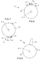
- the embodiment of the backstop shown in FIG. 7 differs from 6 that in that instead of the rolling elements 10g clamping wedges 10m be used.
- FIGS. 9 and 10 show two views of an upper part 5 of one another preferred embodiment of a backrest 2 according to the invention
- this embodiment includes the lever system of the locking means 9 for fixing A of upper backrest part 5 in the normal use position with the upper one Backrest part 5, in particular via a holder 11 with the cross member 5a of the backrest part 5, and connected to the torque generating device 6 Safety lever 9h.
- this is in particular as an um the pivot axis X-X of the upper backrest part 5 pivotable angle lever and is in a locking position shown in FIGS. 9 and 10 by a Locking bolt 9i secured.
- the locking pin 9i reaches through in the locking position Opening 9k in one angle leg of the safety lever 9h while the other Angle leg is connected to the torsion spring 6a. From the opening 9k Locking pin 9i in the event of a crash to release the torque-generating device 6 - specifically the torsion spring 6a - be moved out.
- the means 7 for detecting the rear-end collision are operatively connected in this way U with the locking means 9 for fixing A of the upper backrest part 5 in the Normal use position - in the case shown with the locking pin 9i -, and Locking means 9 - specifically the locking pin 9i and the locking lever 9h - stand thus in operative connection B with the torque-generating device 6 (Torsion spring 6a) that in the event of an impact release of the torque-generating Device 6 is initiated pyrotechnically by the locking means 9, i.e. preferably by means of an ignition cartridge.
- the pyrotechnic Device 12 can - as shown - in the holder 11 for the locking pin 9i be arranged.
- FIGS. 9 and 10 differs from a special backstop 13 provided, via which the locking lever 9h is connected to the torsion spring 6a.
- This backstop 13 serves as an assembly aid and blocks pivoting of the upper backrest part 5 in the direction S from its normal position of use in its Safety position, however, allows pivoting in the opposite direction to.
- the backstop 13 can be a self-locking, positive and / or non-positive - preferably clamping - acting rolling element or wedge lock or as Locking device can be designed such that it is also in between the safety position and the normal use position of the upper backrest part (5) lying positions enables a lock.
- the backstop 13 can as well be carried out as the locking means 10 described above for fixing K of the upper backrest against a backward movement from the safety position into the Normal use position, only that it works in the opposite direction.
- the Backstop 13 can advantageously be achieved to facilitate assembly, by first, for example, the locking pin 9i in the opening 9k of the Safety lever 9h is introduced, which is preferably in the form of an elongated hole can be formed, and then by means of a tool, the torsion spring 6a (counter the direction S) is tensioned, the backstop 13 this tensioning allows, however, an unwanted snap back (relaxation) of the torsion spring 6a prevented. In the event of a crash, however, such relaxation of the torsion spring 6a is possible, there after removing the locking pin 9i of the backstop on the torsion spring 6a held locking lever 9h can be moved.
- the invention is not limited to the illustrated embodiments are limited. This could be the case, for example Lever system other than shown or as described and executed be arranged elsewhere. As for the graphic representation, so are 6 to 8 partially shown schematically. With regard to other possible Details of the backrest 2 according to the invention and a method that can be implemented therewith to prevent accident-related injuries to a seat user to the German patent application 199 38 904.7 mentioned at the beginning directed.
Description
Die vorliegende Erfindung betrifft eine Rückenlehne für einen Fahrzeugsitz mit einer integrierten Schutzeinrichtung gegen unfallbedingte Verletzungen eines Sitzbenutzers im Falle eines Heckaufpralls, insbesondere gegen Halswirbelsyndrom bzw. Schleudertrauma, mit einem unteren, mit einem Sitzteil verbundenen Lehnenteil und mit einem oberen Lehnenteil, das um eine in der Rückenlehne quer zur Fahrzeuglängsachse verlaufende Achse relativ zum unteren Lehnenteil aus einer Normal-Gebrauchsstellung heraus in einer in Fahrtrichtung weisenden Schwenkrichtung durch ein Drehmoment um einen Winkelbereich in eine Sicherheitsstellung verschwenkbar ist, wobei die Schutzeinrichtung eine Einrichtung zur Erzeugung des Drehmomentes Mittel zur Detektierung eines Heckaufpralls und Arretiermittel zur Fixierung des oberen Lehnenteils in der Normal-Gebrauchsstellung aufweist (s. zum Beispiel DE 19 743 339 A1).The present invention relates to a backrest for a vehicle seat with a integrated protective device against accidental injuries to a seat user in the event of a rear impact, especially against cervical spine syndrome or whiplash, with a lower backrest part connected to a seat part and with a upper backrest part, which is in the backrest transverse to the vehicle's longitudinal axis extending axis relative to the lower backrest part from a normal use position out in a swivel direction pointing in the direction of travel by a torque is pivotable through an angular range into a safety position, the Protective device a device for generating the torque means Detection of a rear impact and locking means for fixing the upper part of the backrest in the normal position of use (see, for example, DE 19 743 339 A1).
Die heutige Entwicklung in der Fahrzeugtechnik geht vielfach dahin, daß mit den zur Verfügung stehenden Materialien und Konstruktionsmethoden die Rückenlehnen der Fahrzeugsitze leicht, aber mit hoher Steifigkeit ausgeführt werden, um bei geringem Gewicht dennoch den auftretenden hohen Belastungen bei einem Unfallgeschehen standzuhalten und den Körper des Fahrzeug-Insassen ausreichend abzustützen. Dies führt aber dazu, daß beispielsweise bereits bei einem sogenannten Stoßstangen-Unfall bei niedriger Geschwindigkeit im Bereich von 10 bis 30 km/h (low speed crash), bei dem eine Beschleunigung (ca. 8 - 20 g) des Körpers auftritt, eine Schädigung von dessen Halsmuskulatur und Halswirbelsäule entstehen kann, weil die Stoßkraft nahezu ungedämpft auf die Person einwirkt. Es tritt ein unerwünschter Effekt, der sogenannte Peitscheneffekt auf Kopf und Hals auf, der zu einem Schleudertrauma - einer Überdehnung und Überbelastung der Halswirbelsäule und der Haltemuskulatur des Kopfes - führt. Dieser Effekt und die dabei insbesondere im Halsbereich möglichen Wirbelsäulenverletzungen sind auch unter dem englischen Begriff "whiplash" bekannt.The current development in vehicle technology is often that with the Available materials and construction methods the backrests of the Vehicle seats run light but with high rigidity to be low Weight nevertheless the high loads occurring in the event of an accident withstand and adequately support the body of the vehicle occupant. This but leads to the fact that, for example, already in a so-called bumper accident at low speed in the range of 10 to 30 km / h (low speed crash), at an acceleration (approx. 8 - 20 g) of the body, a damage of whose neck muscles and cervical spine can develop because the impact force is almost acts undamped on the person. An undesirable effect occurs, the so-called Whip effect on the head and neck, which leads to whiplash - an overextension and overloading the cervical spine and the muscles of the head - leads. This effect and the possible spinal injuries, especially in the neck area are also known under the English term "whiplash".
Zum Schutz gegen diese Verletzungen sind passive und aktive Vorrichtungen bekannt, wobei letztere bei einem Unfall aktiv den Abstand zwischen dem Kopf der Person und der Kopfstütze der Rückenlehne verkürzen sollen. Eine solche bekannte (aktive) Vorrichtung der eingangs genannten Art ist in der o.g. DE 197 43 339 A1 beschrieben. Dabei trifft der durch sein Beharrungsvermögen bei einem Aufprall relativ zur Fahrtrichtung in die Rückenlehne des Fahrzeugsitzes beschleunigte bzw. nach rückwärts gebogenen Körper des Fahrzeuginsassen (Sitzbenutzers) auf ein unterhalb der Schwenkachse des oberen Lehnenteils angebrachtes Prallblech auf, das schwenkbar mit dem oberen Lehnenteil, insbesondere mit einer Kopfstütze am Lehnenteil, verbunden ist. Durch die Relativbewegung des Prallblechs nach hinten schwenkt die Kopfstütze nach vom. Mit der Kopfstützenbewegung soll die Wirkung des Peitscheneffektes vermindert werden.To protect against these injuries, passive and active devices are known the latter actively separating the head from the person and in the event of an accident the headrest of the backrest should shorten. Such a known (active) device of the type mentioned is in the above DE 197 43 339 A1 described. there due to its persistence in the event of an impact, it hits in relative to the direction of travel the backrest of the vehicle seat accelerated or bent backwards Body of the vehicle occupant (seat user) on a below the pivot axis baffle plate attached to the upper part of the backrest, which swivels with the upper part Backrest part, in particular with a headrest on the backrest part, is connected. Through the Relative movement of the baffle plate swivels the headrest away from. With the headrest movement should reduce the effect of the whip effect.
Nachteilig ist hierbei, daß die Relativbewegung der Kopfstütze erst durch den in die Rückenlehne hineingeschleuderten Insassen erfolgt. Das obere Lehnenteil kann dadurch in Schwenkrichtung nur um einen Wert beschleunigt werden, der maximal gleich dem Beschleunigungswert ist, den der Fahrzeugsitz durch den Aufprall erfährt. Da sich aber das Bewegungsverhalten des Sitzbenutzers nicht in jedem Fall genau vorhersehen läßt, können deshalb unter Umständen durch die aktive Gegenbewegung der Rückenlehne bzw. Kopfstütze sogar falsche, nicht gewollte, womöglich gefährliche, Effekte auftreten. So kann der Aufprall des Kopfes des Insassen sogar noch verstärkt und auch ein Aufsteigen des Insassen (Vertikalbewegung im Sitz nach oben) nicht vermieden werden. Bei einem Heckaufprall wird nämlich der Insasse derart in die meist aus der Senkrechten nach rückwärts geneigte Rückenlehne geschleudert, daß er das Bestreben hat, an der Rückenlehne, ähnlich einer Rampe, nach oben aufzusteigen. Dies führt in der Regel zum Versagen der Rückenlehne, die durch Überbelastung abknickt und nicht mehr in der Lage ist, den Insassen abzustützen. Insbesondere kann der Kopf des Sitzbenutzers so in eine Höhenposition gelangen, die sich oberhalb der Kopfstütze befindet, wo er nicht mehr abgestützt werden kann. Somit besteht bei der bekannten Rückenlehne ein erhebliches Unfallrestrisiko.The disadvantage here is that the relative movement of the headrest only in the Backrest thrown into the occupants. The upper part of the backrest can can only be accelerated in the swivel direction by a value that is maximum is equal to the acceleration value that the vehicle seat experiences as a result of the impact. However, since the movement behavior of the seat user is not precise in every case can therefore foresee under certain circumstances through the active countermovement the backrest or headrest even wrong, unwanted, possibly dangerous, Effects occur. The impact of the occupant's head can be intensified and also an ascent of the occupant (vertical movement in the seat upwards) not be avoided. In the event of a rear-end collision, the occupant is usually in such a way hurled from the vertical backward inclined backrest that he Has to strive to ascend the backrest, like a ramp. This usually leads to back failure due to overload kinks and is no longer able to support the occupant. In particular, can the head of the seat user can reach a height position that is above the Headrest is where it can no longer be supported. Thus there is at known backrest a considerable risk of accident.
Mechanismen, die durch das Verlagern des Körpers des Fahrzeuginsassen entgegen der Fahrtrichtung in die Rückenlehne hinein ausgelöst werden, zeigen nicht die gewünschte Schutzwirkung. Als besonderer Nachteil erweisen sich die unterschiedlichen Größenabmessungen und die damit einhergehenden Gewichte der Fahrzeugbenutzer. Basierend hierauf ist nicht sicher gewährleistet, daß die Auslöseeinrichtung einer Schutzeinrichtung getroffen und wirksam wird. Ein weiterer Unsicherheitsfaktor ist die träge Reaktion der bisher bekannt gewordenen derartigen Mechanismen. Eine wesentliche Rolle spielt auch die Ausführung der Polsterung der Rückenlehne; diese sollte möglichst dünn im Bereich der Auslöseeinrichtung sein. Dies würde aber wiederum zu einer unerwünschten Verschlechterung des Polsterkomforts führen.Mechanisms opposed by moving the body of the vehicle occupant the direction of travel into the backrest are not shown desired protective effect. They prove to be a particular disadvantage different size dimensions and the associated weights of the Vehicle user. Based on this, there is no guarantee that the triggering device protective device is taken and becomes effective. Another The uncertainty factor is the sluggish reaction of the previously known ones Mechanisms. The design of the upholstery also plays an important role Backrest; this should be as thin as possible in the area of the triggering device. This would in turn lead to an undesirable deterioration in the comfort of the upholstery to lead.
In der nicht vorveröffentlichten deutschen Patentanmeldung 199 38 904.7 ist daher vorgeschlagen worden, daß eine sichere Auslösung der Schutzeinrichtung unabhängig von der Konstitution des Fahrzeuginsassen bei einer Mindestbeschleunigung, welche z.B. am Fahrzeugsitz gemessen werden kann, erfolgt. Der gemessene Beschleunigungswert wird bei einem Kleinwagen bei einer wesentlich geringeren Auffahrgeschwindigkeit erreicht, als dies der Fall bei einer Limousine mit großer dämpfender Knautschzone oder bei einem Lastkraftwagen ist. Die vorgeschlagene Schutzeinrichtung weist einerseits eine Einrichtung auf, die unabhängig von einer Belegung des Fahrzeugsitzes das in Schwenkrichtung auf das obere Lehnenteil wirkende Drehmoment erzeugt, andererseits umfaßt sie Mittel zur Detektierung eines Heckaufpralls, die derart in Wirkverbindung mit der drehmomentenerzeugenden Einrichtung stehen, daß die Einrichtung im Falle des Heckaufpralls aktiviert und die Schwenkbewegung eingeleitet wird. Des weiteren sind dabei auch Arretiermittel zur Fixierung des oberen Lehnenteils in der Normal-Gebrauchsstellung und Arretiermittel zur Fixierung des oberen Lehnenteils gegen eine Rückbewegung aus der Sicherheitsstellung in die Normal-Gebrauchsstellung vorgesehen.In the unpublished German patent application 199 38 904.7 is therefore it has been proposed that a safe triggering of the protective device is independent on the constitution of the vehicle occupant at a minimum acceleration, which e.g. can be measured at the vehicle seat. The measured acceleration value is in a small car at a much lower approach speed achieved than is the case with a sedan with great damping Crumple zone or in a truck. The proposed protective device on the one hand has a device that is independent of occupancy of the vehicle seat that acts on the upper backrest part in the pivoting direction Generates torque, on the other hand it includes means for detecting a rear impact, that in operative connection with the torque-generating device stand that the device is activated in the event of a rear impact and the Swiveling movement is initiated. Furthermore, locking means are also available Fixation of the upper backrest part in the normal use position and locking device to fix the upper backrest against a backward movement from the safety position provided in the normal use position.
Der vorliegenden Erfindung liegt die Aufgabe zugrunde, mit konstruktiv wenig aufwendigen Mitteln eine Rückenlehne der genannten Art zu schaffen, deren Schutzeinrichtung einen verbesserten Verletzungsschutz des jeweiligen Sitzbenutzers gewährleistet, insbesondere durch eine verbesserte Abfangmöglichkeit und Dämpfung beim Auftreffen des Kopfes sowie des Oberkörpers der auf dem Sitz befindlichen Person auf die Kopfstütze bzw. die Rückenlehne. Dabei soll insbesondere in der Normal-Gebrauchsstellung und zusätzlich in der Sicherheitsstellung eine wirksame, aber den Auslösevorgang nicht behindernde Arretierung realisiert werden.The present invention has for its object with little design expensive means to create a backrest of the type mentioned, the Protection device an improved protection against injury to the respective seat user guaranteed, in particular by an improved interception and damping when hitting the head and the upper body of those on the seat Person on the headrest or the backrest. In particular, in the Normal use position and additionally in the safety position an effective, but the locking process does not hinder the triggering process.
Die der Erfindung zugrundeliegende Aufgabe wird durch eine Rückenlehne der eingangs genannten Art gelöst, die dadurch gekennzeichnet ist, daß die Einrichtung zur Erzeugung des Drehmomentes aus einem unabhängig von einer Belegung des Fahrzeugsitzes wirkenden Kraftoder Energiespeicher, die Mittel zur Detektierung eines Heckaufpralls durch einen Fahrzeug-Crash-Sensor, wie einen Beschleunigungssensor, und die Arretiermittel aus einem Hebelsystem gebildet sind, wobei der Fahrzeug-Crash-Sensor derart in Wirkverbindung mit dem Kraft- oder Energiespeicher und mit dem die Arretiermittel zur Fixierung des oberen Lehnenteils bildenden Hebelsystem steht, daß im Falle des Heckaufpralls die Fixierung des oberen Lehnenteils in der Normal-Gebrauchsstellung aufgehoben, der Kraft- und Energiespeicher aktiviert und dadurch die Schwenkbewegung eingeleitet wird.The object underlying the invention is achieved by a backrest solved type mentioned, which is characterized in that the device for generating the torque from a force acting independently of an occupancy of the vehicle seat Energy storage, the means for detecting a rear impact by a Vehicle crash sensor, such as an acceleration sensor, and the locking means are formed from a lever system, the vehicle crash sensor being so in Active connection with the power or energy storage and with which the locking means to fix the upper backrest-forming lever system is that in the case of Rear impact the fixation of the upper backrest part in the normal use position canceled, the power and energy storage activated and thereby the pivoting movement is initiated.
Erfindungsgemäß kann dabei insbesondere durch die Entarretierung des Hebelsystems das Verschwenken des oberen Lehnenteils vorzugsweise derart schnell verlaufen, daß das obere Lehnenteil sich in der Sicherheitsstellung befindet, ehe eine durch den Heckaufprall bedingte Kopfbewegung des Sitzbenutzers einsetzt. In der Sicherheitsstellung liegt das obere Lehnenteil unmittelbar am Körper des Sitzbenutzers an, so daß dieser sich vorteilhafterweise trotz der durch den Aufprall auf ihn wirkenden Beschleunigung nicht mehr nach hinten, entgegen der Fahrtrichtung des Fahrzeugs, frei bewegen und sich Unfallschäden zuziehen kann.According to the invention, in particular by unlocking the Lever system the pivoting of the upper backrest part preferably so quickly run that the upper backrest part is in the safety position before one head movement caused by the rear impact of the seat user. In the In the safety position, the upper backrest part lies directly on the body of the seat user so that it is advantageous despite the impact on it by the impact Acceleration no longer backwards, against the direction of travel of the vehicle, can move freely and suffer accidental damage.
Bei der erfindungsgemäßen Rückenlehne ist es hinsichtlich der Effizienz der Schutzeinrichtung besonders vorteilhaft, wenn in oder an dem oberen Lehnenteil eine Kopfstütze befestigt ist. Dabei ist es günstig, die Kopfstütze, die in der Regel zum Einstellen der Höhenposition an Haltestangen geführt wird, in der Rückenlehne in Höhe des Schulterbereiches um eine zur Fahrzeugachse quer verlaufenden Achse kippbar zu lagern. Zu diesem Zweck kann z.B. ein oberer Querholm der Rückenlehne in oberen Abschnitten der Seitenholme der Rückenlehne mittels einer Schwenklagerung befestigt sein. Allerdings kann das obere Lehnenteil auch derartig ausgebildet sein, daß es die Funktion einer Kopfstütze übernimmt. In jedem Fall kann sich dadurch die jeweilige, den Fahrzeugsitz benutzende Person - vornehmlich bei besonderem Schutz des Hals- und Kopfbereiches - gleichmäßig unter abbremsender Energieabsorption durch den Fahrzeugsitz in die Lehne - hineinbewegen. Für die Kopfstütze wird somit erreicht, daß diese sich bei Vorliegen der Normal-Gebrauchsstellung der Rückenlehne in einer sogenannten Komfortstellung befindet, in der ihr Abstand zum Kopf eines Sitzbenutzers etwa 40 bis 110 mm betragen kann. Durch die Schwenkbewegung des oberen Lehnenteils wird die Kopfstütze dann in eine sogenannte Abfangstellung überführt, in der ihr Abstand zum Kopf eines Sitzbenutzers Null oder nahezu Null ist. Der Normal-Gebrauchsstellung und der Sicherheitsstellung des oberen Lehnenteils entsprechen bei Vorhandensein einer Kopfstütze somit deren Komfort- und die Abfangstellung.In the backrest according to the invention, it is in terms of efficiency Protective device is particularly advantageous if one in or on the upper backrest part Headrest is attached. It is convenient to use the headrest, which is usually used Adjusting the height position is carried out on handrails, in the backrest Height of the shoulder area around an axis transverse to the vehicle axis tiltable storage. For this purpose e.g. an upper cross member of the backrest in the upper sections of the side rails of the backrest by means of a swivel bearing be attached. However, the upper backrest part can also be designed in this way be that it takes on the function of a headrest. In any case, it can the respective person using the vehicle seat - especially if there is something special Protection of the neck and head area - evenly while braking energy absorption through the vehicle seat into the backrest - move in. For the headrest is thus achieved that this is in the presence of the normal position of use Backrest is in a so-called comfort position, in which its distance from the Head of a seat user can be about 40 to 110 mm. Through the The headrest then turns into a swiveling movement of the upper backrest part so-called intercept position, in which their distance to Head of a seat user is zero or almost zero. The normal use position and correspond to the safety position of the upper backrest part in the presence of one Headrest thus their comfort and the interception position.
Als drehmomenterzeugende Einrichtung für die Schwenkbewegung des die Kopfstütze tragenden Querholmes ist dabei ein Kraft- oder Energiespeicher vorgesehen. Hierbei hat sich insbesondere eine vorgespannte Drehfeder als vorteilhaft erwiesen, weil diese eine sehr geringe Eigenbeschleunigung aufweist und daher im Vergleich zu Zug- oder Druckfedern weniger Bauraum bei gleicher Wirkung erfordert.As a torque-generating device for the pivoting movement of the The crossbar carrying the headrest is a power or energy store intended. A preloaded torsion spring has been found to be particularly advantageous proven because this has a very low self-acceleration and therefore in Compared to tension or compression springs, less installation space with the same effect is required.
Das Hebelsystem der Arretiermittel zur Fixierung des oberen Lehnenteils in der Normal-Gebrauchsstellung kann dabei in bevorzugter Weise aus mindestens zwei zusammenwirkenden Hebeln besteht. Ein erster Hebel - im weiteren Klinke genannt - kann den durch die Drehfeder vorgespannten schwenkbaren Querholm gegenüber einem feststehenden Gegenlager abstützen, während ein zweiter Hebel, der im weiteren Arretierhebel genannt wird, als Arretierung der Klinke wirkt. Bei einem Heckaufprall wird der Arretierhebel derart verschwenkt, daß er die Arretierung der Klinke freigibt. Das Auslösen des Arretierhebels kann mit einer nur sehr geringen Betätigungskraft realisiert werden, wodurch eine sehr schnelle Hebelbewegung und damit eine rasche Entriegelung der Klinke möglich ist.The lever system of the locking means for fixing the upper backrest part in the Normal use position can preferably consist of at least two cooperating levers. A first lever - hereinafter referred to as a jack - can opposite the pivotable cross member biased by the torsion spring support a fixed counter bearing, while a second lever, which is further Locking lever is called, acts as locking the pawl. In the event of a rear impact the locking lever is pivoted in such a way that it releases the locking of the pawl. The locking lever can be released with only a very small actuating force can be realized, whereby a very fast lever movement and thus a quick Unlocking the pawl is possible.
Die Betätigung des Arretierhebels kann in bevorzugter Weise durch einen Elektromagneten erfolgen, der seinen Impuls von dem Fahrzeug-Crash-Sensor, wie einem Beschleunigungssensor, erhält welcher als ein Mittel zur Detektierung des Heckaufpralls eingesetzt wird.The locking lever can preferably be actuated by an electromagnet take place, its pulse from the vehicle crash sensor, like one Acceleration sensor, which receives as a means of detecting the rear impact is used.
Nach Freigabe der Klinke schwenkt diese aus ihrer Abstützstellung heraus, wobei sich der Querholm der Rückenlehne mit der Kopfstütze in Richtung auf den Hinterkopf des Fahrzeuginsassen bewegen kann.After release of the pawl, it pivots out of its support position, whereby the crossbar of the backrest with the headrest towards the back of the head Vehicle occupants can move.
Nach einem Auslösen der Schutzeinrichtung kann diese durch erneute Aktivierung der Einrichtung, die das in Schwenkrichtung auf das obere Lehnenteil wirkende Drehmoment erzeugt (z.B. durch Spannen der Drehfeder), wieder in ihre Ausgangsposition gebracht werden, wobei dieser Vorgang aus Sicherheitsgründen nur in einer Werkstatt, in der nach einem Crash gleichzeitiq auch die Sitzfunktion überprüfbar ist, auszuführen ist.After the protective device has been triggered, this can be activated by reactivating the Means that the torque acting in the pivoting direction on the upper backrest part generated (e.g. by tensioning the torsion spring), back to their starting position brought, this process for safety reasons only in a workshop, in which the seat function can also be checked after a crash is.
Von besonderem Vorteil für eine sichere Verhinderung eines Feder- bzw. Rückpralleffektes beim Wirksamwerden der Schutzeinrichtung ist es, wenn die Arretiermittel zur Fixierung des oberen Lehnenteils gegen eine Rückbewegung aus der Sicherheitsstellung in die Normal-Gebrauchsstellung, die im weiteren auch als Rücklaufsperre bezeichnet werden, derart ausgeführt sind, daß sie nicht nur in der Normal-Gebrauchsstellung und in der Sicherheitsstellung selbst, sondern auch in mehreren dazwischenliegenden Positionen eine Arretierung ermöglichen. Dies kann beispielsweise mittels selbsthemmender, form- und oder kraftschlüssig - vorzugsweise klemmend - wirkender Wälzkörper- oder Keilsperren oder mittels einer Rasteinrichtung realisiert werden. Dabei ist es durch eine geeignete Auslegung der Rücklaufsperre vorteilhafterweise möglich, ein Rücklaufspiel des oberen Lehnenteils (Bewegung in Richtung der Sicherheitsstellung) auf einen maximalen Winkelbetrag von 1° zu begrenzen.Of particular advantage for the safe prevention of a spring or A rebound effect when the protective device takes effect is when the locking means to fix the upper backrest part against a backward movement out of the Safety position in the normal position of use, which in the following also as Backstop are called, are designed so that they are not only in the Normal use position and in the safety position itself, but also in allow several intervening positions to be locked. This can for example by means of self-locking, positive and or non-positive - preferably clamping - acting rolling element or wedge locks or by means of a locking device will be realized. It is through a suitable design of the backstop advantageously possible, a return play of the upper backrest part (movement in Direction of the safety position) to a maximum angle of 1 ° limit.
Weitere vorteilhafte Ausgestaltungsmerkmale der Erfindung sind in den Unteransprüchen sowie der folgenden Beschreibung enthalten.Further advantageous design features of the invention are in the Subclaims and the following description included.
Anhand der Zeichnung soll die Erfindung beispielhaft genauer erläutert werden. Dabei zeigen:
- Fig. 1
- eine perspektivische, teilweise schematisierte Seitenansicht einer erfindungsgemäßen Rückenlehne,
- Fig. 2
- eine Seitenansicht einer bevorzugten Ausführungsform einer erfindungsgemäßen Rückenlehne mit Darstellung eines Sitzbenutzers,
- Fig.3
- eine perspektivische Darstellung des oberen Teils der in Fig. 2 dargestellten erfindungsgemäßen Rückenlehne,
- Fig. 4
- eine seitliche Schnittansicht durch den in Fig. 3 dargestellten oberen Teil der erfindungsgemäßen Rückenlehne in einem mittleren Bereich (Ebene IV-IV-IV-IV),
- Fig. 5
- eine weitere Ausführung einer erfindungsgemäßen Rückenlehne in einer Fig. 4 entsprechenden seitlichen Schnittansicht,
- Fig. 6 bis 8
- drei weitere Ausführungen der Arretiermittel zur Fixierung des oberen Lehnenteils gegen eine Rückbewegung aus der Sicherheitsstellung in die Normal-Gebrauchsstellung einer erfindungsgemäßen Rückenlehne in einer Fig. 4 und 5 entsprechenden seitlichen Schnittansicht.
- Fig. 9
- eine perspektivische Ansicht eines oberen Teils einer weiteren bevorzugten Ausführungsform einer erfindungsgemäßen Rückenlehne,
- Fig. 10
- eine Seitenansicht der in Fig. 9 dargestellten Ausführungsform einer erfindungsgemäßen Rückenlehne.
- Fig. 1
- 2 shows a perspective, partially schematic side view of a backrest according to the invention,
- Fig. 2
- 2 shows a side view of a preferred embodiment of a backrest according to the invention, showing a seat user,
- Figure 3
- 2 shows a perspective illustration of the upper part of the backrest according to the invention shown in FIG. 2,
- Fig. 4
- 3 shows a side sectional view through the upper part of the backrest according to the invention shown in FIG. 3 in a central region (plane IV-IV-IV-IV),
- Fig. 5
- 4 shows a further embodiment of a backrest according to the invention in a side sectional view corresponding to FIG. 4,
- 6 to 8
- three further versions of the locking means for fixing the upper backrest part against a return movement from the safety position into the normal use position of a backrest according to the invention in a side sectional view corresponding to FIGS. 4 and 5.
- Fig. 9
- 2 shows a perspective view of an upper part of a further preferred embodiment of a backrest according to the invention,
- Fig. 10
- a side view of the embodiment shown in Fig. 9 of a backrest according to the invention.
In den verschiedenen Figuren der Zeichnung sind gleiche Teile stets mit denselben Bezugszeichen versehen, so daß sie in der Regel auch jeweils nur einmal beschrieben werden.In the different figures of the drawing, the same parts are always the same Provide reference numerals so that they are usually only described once become.
Wie sich zunächst aus Fig. 1 ergibt, besteht ein Fahrzeugsitz 1 aus einer
erfindungsgemäßen Rückenlehne 2 und einem Sitzteil 3. In die Rückenlehne 2 ist eine
Schutzeinrichtung integriert, die zum Schutz der jeweiligen Person gegen
unfallbedingte Verletzungen, insbesondere gegen Halswirbelsyndrom bzw.
Schleudertrauma im Falle eines Heckaufpralls, dient. Die Rückenlehne 2 weist ein
unteres, mit dem Sitzteil 3 verbundenes Lehnenteil 4 und ein oberes Lehnenteil 5 auf,
das um eine in der Rückenlehne 2 quer zur Fahrzeuglängsachse verlaufende Achse X-X
relativ zum unteren Lehnenteil 4 aus einer Normal-Gebrauchsstellung (in Fig. 1 mit
Vollinie gezeichnet) heraus in einer in Fahrtrichtung F weisenden Schwenkrichtung S
durch ein in Schwenkrichtung S wirkendes Drehmoment um einen Winkelbereich in
eine Sicherheitsstellung (in Fig. 1 mit strichpunktierter Linie gezeichnet) verschwenkbar
ist. 1, a
Erfindungsgemäß weist die Schutzeinrichtung einerseits eine Einrichtung 6 auf, die
unabhängig von einer Belegung des Fahrzeugsitzes 2 das in Schwenkrichtung S auf
das obere Lehnenteil 5 wirkende Drehmoment (Pfeil M in Fig. 1) erzeugt, andererseits
weist sie Mittel 7 zur Detektierung eines Heckaufpralls auf. Sowohl die
drehmomenterzeugende Einrichtung 6 als auch die Detektierungsmittel 7 können
unterschiedlich ausgebildet sein. Daher sind diese Teile der erfindungsgemäßen
Rückenlehne 2 in Fig. 1 nur schematisiert (als Kästchen) gezeichnet.According to the invention, the protective device on the one hand has a
Die drehmomenterzeugende Einrichtung 6 kann beispielsweise mit Vorteil durch einen
Kraft- oder Energiespeicher, insbesondere durch ein vorgespanntes Federelement
oder mehrere vorgespannte Federelemente, gebildet sein. In den verschiedenen
Ausführungen der Erfindung, die in den weiteren Figuren dargestellt sind, ist die
drehmomenterzeugende Einrichtung als in der quer zur Fahrzeuglängsachse
verlaufenden Schwenkachse X-X des oberen Lehnenteils 5 liegende, blattförmige
Drehfeder (Torsionsfeder 6a) ausgebildet, die vorteilhafterweise eine sehr geringe
Eigenbeschleunigung aufweist und bei gleicher Wirkung im Vergleich zu Zug- oder
Druckfedem nur wenig Bauraum erfordert (vgl. insbesondere Fig. 3).The
Die Mittel 7 zur Detektierung des Heckaufpralls können mit Vorteil durch einen
Fahrzeug-Crash-Sensor, wie einen Beschleunigungssensor, gebildet sein. Zur
Detektierung eines sogenannten Low Speed Crash kann der Fahrzeug-Crash-Sensor
dabei derart eingestellt sein, daß er bei einer Beschleunigung a von etwa 40 bis 80
m/s2 anspricht. Wie bereits erwähnt, richtet sich der Wert der Beschleunigung, bei dem
der Sensor anspricht, nach der Art und Ausführung eines jeweiligen Kraftfahrzeugs
(Kleinwagen / Limousine mit dämpfender Knautschzone / Lkw).The
Die Detektierungsmittel 7 können derart in Wirkverbindung mit der drehmomenterzeugenden
Einrichtung 6 stehen, daß die Einrichtung 6 im Falle des Heckaufpralls
aktiviert und die Schwenkbewegung des oberen Lehnenteils 5 eingeleitet wird. Das
untere Lehnenteil 4 verbleibt dabei in seiner ursprünglichen (Normal-Gebrauchs-)
Stellung.The detection means 7 can thus be operatively connected to the torque-generating one
Das untere Lehnenteil 4 und das obere Lehnenteil 5 können bevorzugt zur
Gewährleistung eines optimalen Schutzes des Sitzbenutzers in ihrer jeweiligen, nicht
näher bezeichneten Länge definiert aufeinander abgestimmt sein bzw. die quer zur
Fahrzeuglängsachse verlaufende Achse X-X, um die das obere Lehnenteil 5 verschwenkbar
ist, kann in einer definierten Höhe H im Schulterbereich eines Sitzbenutzers,
vorzugsweise etwa 400 bis 580 mm über dem Sitzteil 3, angeordnet sein.The
In oder an dem oberen Lehnenteil 5 ist eine Kopfstütze 8 befestigt, die bei einem
Heckaufprall aus einer Komfortstellung (in Fig. 1 mit Vollinie gezeichnet), in der ihr
Abstand (A1 in Fig. 2) zum Kopf eines Sitzbenutzers etwa 80 bis 120 mm beträgt, in
eine Abfangstellung (in Fig. 1 mit strichpunktierter Linie gezeichnet) bewegt wird, in der
ihr Abstand (A2 in Fig. 2) zum Kopf eines Sitzbenutzers Null oder nahezu Null ist.In or on the
Des weiteren sind Arretiermittel 9 zur Fixierung des oberen Lehnenteils 5 in der
Normal-Gebrauchsstellung vorgesehen. Die Fixierung wird durch den Pfeil A in Fig. 1
veranschaulicht. Diese Arretiermittel 9 sind, wie nachfolgend anhand der Fig. 3 bis 5 im
weiteren beschrieben wird, durch ein Hebelsystem gebildet. Durch den Pfeil B in Fig. 1
ist dabei angedeutet, daß die Arretiermittel 9 die Wirkung der drehmomenterzeugenden
Einrichtung 6 blockieren können.Furthermore, locking means 9 for fixing the
Die Mittel 7 zur Detektierung eines Heckaufpralls stehen derart in Wirkverbindung (Pfeil
U in Fig. 1) mit den Arretiermitteln 9 zur Fixierung des oberen Lehnenteils 5 in der
Normal-Gebrauchsstellung, daß im Falle des Aufpralls die Fixierung A des oberen
Lehnenteils 5 in der Normal-Gebrauchsstellung und die Blockierung B der
drehmomenterzeugenden Einrichtung 6 aufgehoben wird.The
Weitere Arretiermittel 10, deren Wirkung durch den Pfeil K in Fig. 1 veranschaulicht
wird und die nachstehend unter Bezugnahme auf Fig. 4 bis 8 genauer erläutert
werden, können mit Vorteil zur Fixierung des oberen Lehnenteils 5 gegen eine
Rückbewegung aus der Sicherheitsstellung in die Normal-Gebrauchsstellung vorgesehen
sein.Further locking means 10, the effect of which is illustrated by the arrow K in FIG. 1
is explained in more detail below with reference to FIGS. 4 to 8
can be advantageous to fix the
Die als Ganzes nicht näher bezeichnete, in die erfindungsgemäße Rückenlehne 2 integrierte
Schutzeinrichtung gegen unfallbedingte Verletzungen wird somit in der
beschriebenen Ausführung der Erfindung durch das untere Lehnenteil 4, das um die
Achse X-X schwenkbare obere Lehnenteil 5 mit der Kopfstütze 8, die drehmomenterzeugende
Einrichtung 6, die Mittel 7 zur Detektierung eines Heckaufpralls, die als
Hebelsystem ausgebildeten Arretiermittel 9 zur Fixierung des oberen Lehnenteils 5 in
der Normal-Gebrauchsstellung und die Arretiermittel 10 zur Fixierung des oberen
Lehnenteils 5 gegen eine Rückbewegung aus der Sicherheitsstellung in die Normal-Gebrauchsstellung
gebildet.The not shown as a whole, integrated into the
Fig. 3, die ein vergrößertes Detail der in Fig. 2 dargestellten erfindungsgemäßen
Rückenlehne 2 im Bereich des Übergangs vom unteren Lehnenteil 4 zum oberen
Lehnenteil 5 zeigt, veranschaulicht eine bevorzugte konkrete Ausführungsform für die
Einrichtung 6, die unabhängig von einer Belegung des Fahrzeugsitzes 2 das in
Schwenkrichtung S auf das obere Lehnenteil 5 wirkende Drehmoment M erzeugt, für
die als Hebelsystem ausgebildeten Arretiermittel 9 zur Fixierung des oberen Lehnenteils
5 in der Normal-Gebrauchsstellung und für die Arretiermittel 10 (Rücklaufsperre)
zur Fixierung des oberen Lehnenteils 5 gegen eine Rückbewegung aus der
Sicherheitsstellung in die Normal-Gebrauchsstellung.Fig. 3, which is an enlarged detail of the invention shown in Fig. 2
Die drehmomenterzeugende Einrichtung 6 in Fig. 3 ist, wie bereits erwähnt wurde, als
ein vorgespanntes Federelement - und zwar als eine im oberen Lehnenteil 5 gelagerte
blattförmige Drehfeder 6a ausgebildet. Durch eine solche Drehfeder 6a können vorteilhafterweise
sehr hohe Steltkräfte bzw. ein sehr hohes Drehmoment M erzeugt
werden, die ein Verschwenken des oberen Lehnenteils 5 im Millisekundenbereich
ermöglichen. Für das Federelement hat es sich als vorteilhaft erwiesen, wenn dieses
eine fallende Kennlinie aufweist, die zur Erzeugung einer starken Beschleunigung eine
hohe Anfangskraft, aber nur eine sehr geringe Endkraft aufweist. Dies trägt
insbesondere der Tatsache Rechnung, daß aufgrund seiner Anordnung im Fahrzeug
das obere Lehnenteil 5 durch den Crash eine Beschleunigung erfährt, die entgegen
der Wirkung des Federelementes steht. Es ist insbesondere äußerst vorteilhaft, wenn
die drehmomenterzeugende Einrichtung 6 derart ausgelegt ist, daß sie im Falle ihrer
Aktivierung das obere Lehnenteil 5 in Schwenkrichtung S um einen größeren Betrag
beschleunigt als es ein gemessener oder vorzugsweise ein empirisch bestimmter
mittlerer Betrag der Beschleunigung a ist, den der Fahrzeugsitz 2 durch den Heckaufprall
erfährt, was durch die Federkennlinie (Dicke und Material der Drehfeder 6a)
eingestellt werden kann.The torque-generating
In Fig. 3 sind - wie an sich bekannt - zum Einstellen der Höhenposition vorgesehene
Haltestangen 8a, 8b der Kopfstütze 8 erkennbar, mittels derer die Kopfstütze 8 in der
Rückenlehne 2 in Höhe des Schulterbereiches eines Sitzbenutzers um eine zur
Fahrzeugachse quer verlaufenden Achse X-X kippbar gelagert ist (zur Höhenlage der
Achse X-X siehe H in Fig. 1). Zu diesem Zweck ist ein oberer, die Haltestangen 8a, 8b
tragender Querholm 5a der Rückenlehne 2 in oberen, das untere Lehnenteil 4 überragenden
jeweiligen Befestigungsabschnitten 4a an zwei mit dem unteren Lehnenteil 4
fest verbundenen Seitenholmen 4b um die Achse X-X, in der die Drehfeder 6a liegt,
schwenkbar gelagert (Schwenkrichtung S). Die Drehfeder 6a selbst ist an ihren Enden
seitlich in den Befestigungsabschnitten 4a eingespannt und etwa mittig über ein
Halteteil 6b fest mit dem Querholm 5a verbunden. So kann sie in der - in Fig. 4 ausschließlich
und in Fig. 5 als eine Position dargestellten - Normal-Gebrauchsstellung
durch eine Verdrehung entgegen der bezeichneten Schwenkrichtung S vorgespannt
werden.3, as is known per se, are provided for setting the height
Als Arretiermittel 9 zur Fixierung des oberen Lehnenteils 5 in der Normal-Gebrauchsstellung
ist ein Hebelsystem vorgesehen, das von zwei (nicht näher
bezeichneten) Seitenwänden des insbesondere taschenartig ausgebildeten Halteteils
6b getragen wird und das als eine form- bzw. kraftformschlüssige Sperre wirkt.As a locking means 9 for fixing the
Wie dazu Fig. 4 und insbesondere auch Fig. 5 genauer zeigen, besteht das
Hebelsystem in den dargestellten Ausführungen aus zwei zusammenwirkenden
Hebeln 9a, 9b, die in dem Halteteil 6b schwenkbar gelagert sind. Ein erster,
insbesondere einarmig ausgebildeter, Hebel (Klinke 9a) ist seitlich in Lagern 9c des
Halteteils 6b gelagert, wobei die Lagerachse Y-Y parallel zur Drehachse X-X des
oberen Lehnenteils 5 verläuft, und stützt den durch die Drehfeder 6a vorgespannten
schwenkbaren Querholm 5a gegenüber einem feststehenden Gegenlager 4c ab. Das
Gegenlager 4c befindet sich dabei am oberen Ende eines anderendig fest mit dem
unteren Lehnenteil 4 verbundenen, in das taschenartige Halteteil 6b hineinragenden
Tragteiles 4d und ist durch eine Anschlagfläche für eine etwa am freien Hebelende
angeordnete Nase 9d der Klinke 9a gebildet. In einer Sperrstellung der Klinke 9a liegt
die Nase 9d am Gegenlager 4c an.As shown in FIG. 4 and in particular also in FIG. 5, this exists
Lever system in the versions shown from two interacting
Der zweite, insbesondere zweiarmig ausgebildete, Hebel (Arretierhebel 9b) dient zur
Arretierung der Klinke 9a in ihrer Sperrstellung. Er ist seitlich in Lagern 9e des
Halteteils 6b gelagert, wobei die Lagerachse Z-Z wiederum parallel zur Drehachse X-X
des oberen Lehnenteils 5 verläuft, und greift in seiner Sperrstellung mit einer Sperrnase
9f derart formschlüssig in die Klinke 9a ein, daß diese sich nicht aus ihrer
Sperrstellung herausbewegen kann. Die Darstellungen in Fig. 4 und 5 zeigen jeweils
die Sperrstellungen von Klinke 9a und Arretierhebel 9b.The second, in particular two-armed lever (locking
Bei Eintreten des Bedarfsfalles (Heckaufprall) wird der Arretierhebel 9b um seine
Lagerachse Z-Z - gemäß den Darstellungen in Fig. 4 und 5 - im Uhrzeigersinn - verschwenkt,
wobei der formschlüssige Eingriff der Sperrnase 9f in die Klinke 9a
aufgehoben und die Klinke 9a für eine Schwenkbewegung um ihre Achse Y-Y (gemäß
den Darstellungen in Fig. 4 und 5 - ebenfalls im Uhrzeigersinn) freigegeben wird. Das
Auslösen des Arretierhebels 9b kann dabei mit nur sehr geringer, an einem Hebelende
9g angreifender Betätigungskraft erfolgen und z.B. mit Vorteil mittels eines (nicht
dargestellten) Elektromagneten bewirkt werden, der seinen Schaltimpuls von einem
Sensor (als Mittel 7 zur Detektierung des Heckaufpralls) erhält.When the need arises (rear-end collision), the locking
Nachdem die Klinke 9a durch den Arretierhebel 9b freigegeben ist, wird sie
(entsprechend der gewählten Darstellung - im Uhrzeigersinn) - allein unter der Wirkung
der Drehfeder 6a um ihre Lagerachse Y-Y aus ihrer Sperrstellung in ihre
Freigabestellung geschwenkt. Dabei wird die Reibung zwischen der feststehenden
Anschlagfläche des Gegenlagers 4c und der Abstützfläche an der Nase 9d der Klinke
9a überwunden. Der Querholm 4a schwenkt mit der Kopfstütze 8 in Richtung des
Hinterkopfs des Fahrzeuginsassen (Abfangstellung der Kopfstütze 8). Die Positionen,
die dabei das obere Lehnenteil 5 und die Kopfstütze 8 einnehmen, sind in Fig. 1 - wie
bereits erwähnt - strichpunktiert gezeichnet und in Fig. 5 für die zweite bevorzugte
Ausführung der Erfindung durch strichpunktierte Bezugslinien gekennzeichnet.After the
Die Mittel 7 zur Detektierung des Heckaufpralls könnten - alternativ zur
Sensorausbildung - auch durch ein mechanisches Steuersystem gebildet sein, welches
mechanische Teile aufweist, die - beschleunigt durch die Wirkung des Heckaufpralls -
den Arretierhebel 9b außer Eingriff, d.h. in eine entsperrte Lage bringen. Auch dies
entspricht einer unmittelbaren Wirkverbindung U von den Mitteln 7 zur Detektierung
des Heckaufpralls auf die Arretiermittel 9.The
Als Arretiermittel 10 zur Fixierung des oberen Lehnenteils 5 gegen eine
Rückbewegung des oberen Lehnenteils 5 aus der Sicherheitsstellung in die Normal-Gebrauchsstellung
bzw. der Kopfstütze 8 aus der Abfangstellung in die Komfortstellung
sind gemäß Fig. 3 bis 8 verschiedene Ausführungsformen möglich.As a locking means 10 for fixing the
Es wurde dabei schon eingangs erwähnt, daß diese Arretiermittel 10 (Rücklaufsperre)
zur Unterbindung eines Feder- bzw. Rückpralleffektes beim Wirksamwerden der
Schutzeinrichtung derart ausgeführt sind, daß sie nicht nur in der Normal-Gebrauchsstellung
und in der Sicherheitsstellung des oberen Lehnenteils 5, sondern auch
in dazwischenliegenden Positionen eine Arretierung ermöglichen. Dies kann - wie
anhand der nachstehend beschriebenen verschiedenen Ausführungsformen der
Rücklaufsperre deutlich wird - beispielsweise mittels selbsthemmender, form- und/oder
kraftschlüssig - vorzugsweise klemmend - wirkender Wälzkörper- oder Keilsperren
oder mittels einer Rasteinrichtung realisiert werden. Für die beschriebenen
Ausführungsformen der Rücklaufsperre ist es dabei auf dem Wege einer geeigneten
Auslegung der Rücklaufsperre (Größe und Anzahl von Wälzkörpem, beim
Rückschwenken wirksam werdender Anstieg von Sperrflächen, Anzahl und Größe der
Zähne einer Rastverzahnung usw.) vorteilhafterweise möglich, ein Rücklaufspiel des
oberen Lehnenteils 5 (Rückbewegung entgegen der Schwenkrichtung S in Richtung
der Normal-Gebrauchsstellung des Lehnenteils 5) auf einen maximalen Winkelbetrag
von etwa 1° zu begrenzen.It was mentioned at the beginning that these locking means 10 (backstop)
to prevent a spring or rebound effect when the
Protective device are designed so that they are not only in the normal position of use
and in the safety position of the
Die Ausführung gemäß Fig. 3 und 4 zeigt eine Ausbildung der Arretiermittel 10 zur
Fixierung des oberen Lehnenteils 5, insbesondere des Querholms 5a, als rastender
Ratschenmechanismus. Dabei ist ein Trägerelement 10a für mindestens eine, in der
dargestellten Ausführung für zwei Rastverzahnungen 10b, 10c, innerhalb des
taschenförmigen Halteteils 6b befestigt. Die jeweilige Verzahnung 10b, 10c wirkt mit
mindestens einem, in der dargestellten Ausführung mit zwei, als Gegenrastelemente
fungierenden Zähnen 4e, 4f am Tragteil 4d zusammen. Durch die beiden
Verzahnungen 10b, 10c und die korrespondierenden Gegenzähne 4e, 4f, die jeweils
gegeneinander versetzt sind, wird eine höhere Sicherheit der Rastverbindung und eine
Verkleinerung (Halbierung) des Rücklaufspiels des oberen Lehnenteils 5 erreicht.3 and 4 shows a design of the locking means 10 for
Fixing the
Die Ausführung gemäß Fig. 5 zeigt eine Ausbildung der Arretiermittel 10 zur Fixierung
des oberen Lehnenteils 5, insbesondere des Querholms 5a, als Wälzkörper-Sperreinrichtung.
Diese Wälzkörper-Sperreinrichtung besteht aus einem konzentrisch
um die Schwenkachse X-X des oberen Lehnenteils 5 angeordneten Zahnkranz 10d,
der innerhalb eines zylinderförmigen Mantels 10e angeordnet ist, sowie aus zwischen
den Zähnen 10f des Zahnkranzes 10d sowie zwischen Zahnkranz 10d und Mantel 10e
angeordneten Wälzkörpem 10g. Die Drehfeder 6a ist fest mit dem Zahnkranz 10d
verbunden. Die Zahnflanken der Zähne 10f des Zahnkranzes 10d sind derart
ausgeführt, daß die Wälzkörper-Sperreinrichtung das Verschwenken (Schwenkrichtung
S) in die Sicherheitsstellung des oberen Lehnenteils 5 bzw. in die
Abfangstellung der Kopfstütze 8 zuläßt, da die Wälzkörper 10g zwischen Zahnkranz
10d und Mantel 10e frei rollen können, während im Falle einer gegenläufigen
Bewegung ein Verklemmen der Wälzkörper 10g zwischen Zahnkranz 10d und Mantel
10e erfolgt, das diese Rückbewegung hemmt.5 shows an embodiment of the locking means 10 for fixation
of the
Ein ähnliches Prinzip liegt auch der in Fig. 6 dargestellten Ausführung der
Rücklaufsperre zugrunde. Unterschiede zur vorstehend beschriebenen Ausführung
bestehen hierbei jedoch darin, daß der bzw. die Wälzkörper 10g jeweils unter der
Belastung einer Feder 10h stehen und daß nicht ein dem Zahnkranz 10d
entsprechendes, konzentrisch um die Schwenkachse X-X des oberen Lehnenteils 5
angeordnetes Innenteil 10i Aufnahmen 10k für die Wälzkörper 10g aufweist, sondem
ein dem zylinderförmigen Mantel 10e entsprechendes Mantelteil 10l. Die Funktionsweise
dieser Einrichtung entspricht der vorstehend beschriebenen. Die Wände der
Aufnahmen 10k des Mantelteils 101 sind derart ausgeführt, daß die Wälzkörper-Sperreinrichtung
das Verschwenken (Schwenkrichtung S) in die Sicherheitsstellung
des oberen Lehnenteils 5 bzw. in die Abfangstellung der Kopfstütze 8 zuläßt, da die
Wälzkörper 10g zwischen dem Innenteil 10i und dem Mantelteil 10l gege die Wirkung
der Feder 10h frei rollen können, während im Falle einer gegenläufigen Bewegung
unter der zusätzlich in diese Richtung weisenden Wirkung der Feder 10h ein
Verklemmen der Wälzkörper 10g erfolgt, das diese Rückbewegung hemmt.A similar principle also lies in the embodiment of FIG. 6
Backstop. Differences from the execution described above
however, consist in that the rolling element or
Die in Fig. 7 dargestellte Ausführung der Rücklaufsperre unterscheidet sich von
derjenigen gemäß Fig. 6 dadurch, daß anstelle der Wälzkörper 10g Klemmkeile 10m
verwendet werden.The embodiment of the backstop shown in FIG. 7 differs from
6 that in that instead of the rolling
Bei der in Fig. 8 dargestellten Ausführung der Rücklaufsperre ist wie bei den beiden
vorhergehenden Ausführungen ein zylinderförmiges Innenteil 10i mit glatter (oder auch
zur Reibungserhöhung strukturierter oder mit einem Belag versehener) Mantelfläche
vorgesehen, die Verklemmung im Falle der beschriebenen Rückbewegung erfolgt
jedoch mittels mindestens eines exzentrisch gelagerten, kraftschlüssig an der
Mantelfläche des Innenteils 10i angreifenden Schwenkkörpers 10n.In the embodiment of the backstop shown in Fig. 8 is like the two
previous versions, a cylindrical
Wie bereits erwähnt, zeigen Fig. 9 und 10 zwei Ansichten eines oberen Teils 5 einer
weiteren bevorzugten Ausführungsform einer erfindungsgemäßen Rückenlehne 2. Bei
dieser Ausführung umfaßt das Hebelsystem der Arretiermittel 9 zur Fixierung A des
oberen Lehnenteils 5 in der Normal-Gebrauchsstellung einen fest mit dem oberen
Lehnenteil 5, insbesondere über einen Halter 11 mit dem Querholm 5a des Lehnenteils
5, und mit der drehmomenterzeugenden Einrichtung 6 verbundenen
Sicherungshebel 9h. Dieser ist in der gezeigten Ausführung insbesondere als ein um
die Schwenkachse X-X des oberen Lehnenteils 5 verschwenkbarer Winkelhebel ausgebildet
und ist in einer, in den Fig. 9 und 10 gezeigten Sperrstellung durch einen
Sperrbolzen 9i gesichert. Der Sperrbolzen 9i durchgreift dazu in der Sperrstellung eine
Öffnung 9k in einem Winkelschenkel des Sicherungshebels 9h, während der andere
Winkelschenkel mit der Drehfeder 6a verbunden ist. Aus der Öffnung 9k kann der
Sperrbolzen 9i im Crashfall zur Freigabe der drehmomenterzeugenden Einrichtung 6 -
konkret der Drehfeder 6a - herausbewegt werden.As already mentioned, FIGS. 9 and 10 show two views of an
Die Mittel 7 zur Detektierung des Heckaufpralls stehen dabei derart in Wirkverbindung
U mit den Arretiermitteln 9 zur Fixierung A des oberen Lehnenteils 5 in der
Normal-Gebrauchsstellung - im dargestellten Fall mit dem Sperrbolzen 9i -, und die
Arretiermittel 9 - konkret der Sperrbolzen 9i und der Sicherungshebel 9h - stehen
derart in Wirkverbindung B mit der drehmomenterzeugenden Einrichtung 6
(Drehfeder 6a), daß im Falle des Aufpralls eine Freigabe der drehmomenterzeugenden
Einrichtung 6 durch die Arretiermittel 9, pyrotechnisch initiiert wird, d.h.
vorzugsweise mittels einer Zündpatrone, erfolgt. Die dazu dienende pyrotechnische
Einrichtung 12 kann - wie dargestellt - in dem Halter 11 für den Sperrbolzen 9i
angeordnet sein.The
Des weiteren ist bei der in Fig. 9 und 10 dargestellten Ausführung im Unterschied zu
den vorhergehend dargestellten Ausführungen eine spezielle Rücklaufsperre 13
vorgesehen, über die der Sicherungshebel 9h mit der Drehfeder 6a verbunden ist.
Diese Rücklaufsperre 13 dient als Montagehilfe und blockiert eine Verschwenkung des
oberen Lehnenteils 5 in Richtung S aus seiner Normal-Gebrauchsstellung in seine
Sicherheitsstellung, läßt eine Verschwenkung in entgegengesetzter Richtung jedoch
zu. Die Rücklaufsperre 13 kann als eine selbsthemmende, form- und/oder kraftschlüssig
- vorzugsweise klemmend - wirkende Wälzkörper- oder Keilsperre oder auch als
Rasteinrichtung derart ausgeführt sein, daß sie auch in zwischen der Sicherheitsstellung
und der Normal-Gebrauchsstellung des oberen Lehnenteils (5) liegenden Positionen
eine Arretierung ermöglicht. Im Detail kann die Rücklaufsperre 13 ebenso
ausgeführt sein, wie die vorstehend beschriebenen Arretiermittel 10 zur Fixierung K
des oberen Lehnenteils gegen eine Rückbewegung aus der Sicherheitsstellung in die
Normal-Gebrauchsstellung, nur das sie in umgekehrter Richtung wirkt. Durch die
Rücklaufsperre 13 kann vorteilhafterweise eine Montage-erleichterung erzielt werden,
indem zunächst beispielsweise der Sperrbolzen 9i in die Öffnung 9k des
Sicherungshebels 9h eingeführt wird, die dazu in bevorzugter Weise als Langloch
ausgebildet sein kann, und dann mittels eines Werkzeugs die Drehfeder 6a (entgegen
der Richtung S) verspannt wird, wobei die Rücklaufsperre 13 dieses Verspannen
zuläßt, jedoch ein ungewolltes Zurückschnellen (Entspannen) der Drehfeder 6a
verhindert. Im Crashfall ist ein solches Entspannen der Drehfeder 6a jedoch möglich,
da nach Entfernen des Sperrbolzens 9i der über die Rücklaufsperre an der Drehfeder
6a festgehaltene Sicherungshebel 9h mitbewegt werden kann.Furthermore, the embodiment shown in FIGS. 9 and 10 differs from
a
Wie bereits aus der vorstehenden Beschreibung hervorgeht, ist die Erfindung nicht auf
die dargestellten Ausführungsbeispiele beschränkt. So könnte beispielsweise das
Hebelsystem auch anders als dargestellt bzw. als beschrieben ausgeführt und an
anderer Stelle angeordnet sein. Was die zeichnerische Darstellung anbelangt, so sind
die Fig. 6 bis 8 teilweise schematisiert dargestellt. Im Hinblick auf weitere mögliche
Details der erfindungsgemäßen Rückenlehne 2 und ein damit realisierbares Verfahren
zur Vorbeugung unfallbedingter Verletzungen eines Sitzbenutzers wird
auf die eingangs erwähnte deutsche Patentanmeldung 199 38 904.7
verwiesen. As is already apparent from the above description, the invention is not limited to
the illustrated embodiments are limited. This could be the case, for example
Lever system other than shown or as described and executed
be arranged elsewhere. As for the graphic representation, so are
6 to 8 partially shown schematically. With regard to other possible
Details of the
- 11
- Fahrzeugsitzvehicle seat
- 22
- Rückenlehnebackrest
- 33
- Sitzteilseat part
- 44
- unteres Lehnenteil von 2lower back part of 2
- 4a4a
- Befestigungsabschnitt von 2 bzw. 4bAttachment section of 2 or 4b
- 4b4b
- Seitenholm von 2Side spar of 2
- 4c4c
- Gegenlager für 9a an 4dCounter bearing for 9a to 4d
- 4d4d
- Tragteil an 4Support part on 4
- 4e4e
- erster Zahn an 4dfirst tooth at 4d
- 4f4f
- zweiter Zahn an 4dsecond tooth at 4d
- 55
- oberes Lehnenteil von 2upper backrest part of 2
- 5a5a
- oberer Querholm von 2upper cross spar of 2
- 66
- drehmomentenerzeugende EinrichtungTorque generating device
- 6a6a
- Drehfedertorsion spring
- 6b6b
- Halteteilholding part
- 77
- Mittel zur Detektierung eines HeckaufprallsMeans for detecting a rear impact
- 88th
- Kopfstützeheadrest
- 8a, 8b8a, 8b
- Haltestangen von 8Handrails from 8
- 99
- Arretiermittellocking
- 9a9a
- erster Hebel von 9, Klinkefirst lever of 9, jack
- 9b9b
- zweiter Hebel von 9, Arretierhebelsecond lever of 9, locking lever
- 9c9c
- Lager für 9a in 6bBearings for 9a in 6b
- 9d9d
- Nase an 9a (zum Anschlag an 4c)Nose at 9a (to stop at 4c)
- 9e9e
- Lager für 9b in 6bBearings for 9b in 6b
- 9f9f
- Sperrnase für 9a an 9bLocking nose for 9a on 9b
- 9g9g
- Hebelende (Kraftangriff zur Betätigung)Lever end (force application for actuation)
- 9h9h
- Sicherungshebelsafety lever
- 9i9i
- Sperrbolzenlocking pin
- 9k9k
- Öffnung in 9h für 9i Opening in 9h for 9i
- 1010
- Arretiermittellocking
- 10a10a
- Trägerelement für 10b/10c von 10Support element for 10b / 10c of 10
- 10b10b
- erste Rastverzahnung an 10afirst locking teeth on 10a
- 10c10c
- zweite Rastverzahnung an 10asecond locking teeth on 10a
- 10d10d
- Zahnkranz von 10Sprocket of 10
- 10e10e
- Mantel von 10Coat of 10
- 10f10f
- Zahn von 10dTooth of 10d
- 10g10g
- Wälzkörper von 10Rolling elements from 10
- 10h10h
- Feder an 10g/10mSpring at 10g / 10m
- 10i10i
- Innenteil von 10Inner part of 10
- 10k10k
- Aufnahme für 10g/10m in 10d/10lRecording for 10g / 10m in 10d / 10l
- 10l10l
- Mantelteil von 10Mantle part of 10
- 10m10m
- Klemmkeil von 10Wedge of 10
- 10n10n
- Schwenkkörper von 10Swivel body of 10
- 1111
- Halter für 9i und 12Bracket for 9i and 12
- 1212
- pyrotechnische Einrichtungpyrotechnic device
- AA
- Wirkverbindung von 9 auf 5Active connection from 9 to 5
- A1A1
- Abstand zwischen Kopf und 8 (Komfortstellung)Distance between head and 8 (comfort position)
- A2A2
- Abstand zwischen Kopf und 8 (Abfangstellung)Distance between head and 8 (catch position)
- aa
- Beschleunigungacceleration
- BB
- Wirkverbindung von 9 auf 6Active connection from 9 to 6
- FF
- Fahrtrichtungdirection of travel
- HH
- Höhe, Abstand zwischen 3 und X-XHeight, distance between 3 and X-X
- KK
- Wirkverbindung von 10 auf 5Active connection from 10 to 5
- MM
- Drehmoment, Wirkverbindung von 6 auf 5Torque, active connection from 6 to 5
- SS
- Schwenkrichtung von 5 bzw. 8Swiveling direction of 5 or 8
- UU
- Wirkverbindung von 7 auf 9Active connection from 7 to 9
- X-XX X
- Lager- und Schwenkachse von 5/6Bearing and swivel axis from 5/6
- Y-YY-Y
- Lager- und Schwenkachse von 9aBearing and swivel axis from 9a
- Z-ZZ-Z
- Lager- und Schwenkachse von 9bBearing and swivel axis from 9b
Claims (22)
- Backrest (2) for a vehicle seat (1) having an integrated protection device (4, 5, 6, 7, 8, 9, 10, 11, 12, 13) against accident-induced injuries to a seat user in the event of a rear impact, in particular against cervical vertebrae syndrome or whiplash, having a lower backrest part (4) which is connected to a seat part (3) and having an upper backrest part (5) which can be caused by a torque (M) acting in the pivoting direction to pivot by an angular range about an axis (X-X), which runs in the backrest (2) transversely with respect to the longitudinal axis of the vehicle, relative to the lower backrest part (4) from a normal use position in a pivoting direction (S) pointing in the direction of travel (F) into a safety position, the protection device (4, 5, 6, 7, 8, 9, 10, 11, 12, 13) having a device (6) for producing the torque (M), means (7) for detecting a rear impact and arresting means (9) for fixing (A) the upper backrest part (5) in the normal use position, characterized in that the device (6) for producing the torque (M) is formed from a force or energy store which operates irrespective of whether the vehicle seat (2) is occupied, the means (7) for detecting a rear impact are formed by a vehicle crash sensor, such as an acceleration sensor, and the arresting means (9) are formed from a lever system, the vehicle crash sensor being operatively connected (U, B) to the force or energy store and to the lever system forming the arresting means (9) for fixing (A) the upper backrest part (5) in such a manner that, in the event of the rear impact, the fixing (A) of the upper backrest part (5) in the normal use position is cancelled, the force and energy store is activated and the pivoting movement is thereby initiated.
- Backrest according to Claim 1, characterized in that a head restraint (8) is fastened in or to the upper backrest part (5) and, during a rear impact, is moved from a comfort position, in which its distance (A1) from the head of a seat user is approximately 40 to 110 mm, into an intercepting position, in which its distance (A2) from the head of a seat user is zero or virtually zero.
- Backrest according to Claim 1 or 2, characterized in that the torque-generating device (6) is formed by a prestressed spring element or by a plurality of prestressed spring elements.
- Backrest according to Claim 3, characterized in that the spring element is formed by a torsion spring (6a) which is preferably arranged in the pivoting axis (X-X).
- Backrest according to Claim 3 or 4, characterized in that the means (7) for detecting a rear impact are operatively connected (U) to the arresting means (9) for fixing (A) the upper backrest part (5) in the normal use position in such a manner, and the arresting means (9) are operatively connected (B) to the torque-generating device (6) in such a manner, that, in the event of the impact, the prestressed spring element, in particular the torsion spring (6a), is released by the arresting means (9).
- Backrest according to one of Claims 1 to 5, characterized by arresting means (10) for fixing (K) the upper backrest part (5) against a movement back out of the safety position into the normal use position.
- Backrest according to one of Claims 1 to 6, characterized in that the lever system of the arresting means (9) for fixing (B) the upper backrest part (5) in the normal use position is formed from at least two interacting levers (9a, 9b).
- Backrest according to one of Claims 1 to 7, characterized in that the lever system of the arresting means (9) for fixing (A) the upper backrest part (5) in the normal use position comprises a securing lever (9h) which is connected fixedly to the upper backrest part (5), in particular to a transverse strut (5a) of the backrest part (5) via a holder (11), and to the torque-generating device (6), in particular an angle lever which can be pivoted about the pivoting axis (X-X) of the upper backrest part (5) and is secured in a locking position by a locking pin (9i).
- Backrest according to Claim 8, characterized in that in the locking position, the locking pin (9i) reaches through an, in particular, slot-like opening (9k) of the securing lever (9h), out of which it is moved in order to release the torque-generating device (6).
- Backrest according to Claim 8 or 9, characterized in that the securing lever (9h) is connected to the torsion spring (6a) via a return lock (13) which blocks a pivoting of the upper backrest part (5) in the direction (S) from its normal use position into its safety position, but permits it in the opposite direction.
- Backrest according to Claim 10, characterized in that the return lock (13) is designed as a self-locking rolling-element lock or wedge-type lock which operates in a form-fitting and/or frictional manner - preferably in a clamping manner - or as a latching device, in such a manner that it also makes arresting possible in positions lying between the safety position and the normal use position of the upper backrest part (5).
- Backrest according to one of Claims 1 to 7, characterized in that the lever system is formed from a catch (9a) which is mounted pivotably in the upper backrest part (5), in particular in a transverse strut (5a) of the backrest part (5), and, in a locking position, is supported on a counterbearing (4c) fixed relative to the upper backrest part (5), and from a pivotably mounted arresting lever (9b) which, in a locking position, engages in the catch (9a) and, in a release position, releases the catch (9a).
- Backrest according to one of Claims 1 to 12, characterized in that the lever system is mounted in side walls of a pocket-like retaining part (6b) arranged in the upper backrest part (5).
- Backrest according to Claim 12 or 13, characterized in that the counterbearing (4c) is arranged at an upper end of a supporting part (4d), which is connected at the other end fixedly to the lower backrest part (4) and preferably protrudes into the pocket-like retaining part (6b), and is formed by a stop surface for a lug (9d) of the catch (9a), which lug is arranged, for example, at a free end of the lever.
- Backrest according to one of Claims 12 to 14, characterized in that a movement of the arresting lever (9b) from its locking position into its release position is brought about by means of an electromagnet which obtains its switching pulse from a sensor in the form of means (7) for detecting the rear impact.
- Backrest according to one of Claims 6 to 15, characterized in that the arresting means (10) for fixing (K) the upper backrest part (5) against a movement back out of the safety position into the normal use position are designed in each case as a self-locking rolling-element lock or wedge-type lock which operates in a form-fitting and/or frictional manner - preferably in a clamping manner - or as a latching device, the arresting means (10) preferably also making arresting possible against a movement back in positions lying between the safety position and the normal use position of the upper backrest part (5).
- Backrest according to one of Claims 6 to 16, characterized in that the arresting means (10) for fixing (K) the upper backrest part (5) against a movement back out of the safety position into the normal use position is designed as a latching ratchet mechanism having at least one, preferably two, latching toothings (10b, 10c), which are fastened, in particular, within the pocket-shaped retaining part (6b), and having at least one, preferably two, teeth (4e, 4f) which act as mating latching elements and are arranged, in particular, on the supporting part (4d).
- Backrest according to one of Claims 6 to 16, characterized in that the arresting means (10) for fixing (K) the upper backrest part (5) against a movement back out of the safety position into the normal use position are designed as a rolling-element locking device which comprises a toothed ring (10d) which is arranged concentrically about the pivoting axis (X-X) of the upper backrest part (5) and is arranged within a cylindrical casing (10e), and rolling elements (10g) arranged between the teeth (10f) of the toothed ring (10d) and between the toothed ring (10d) and casing (10e).
- Backrest according to one of Claims 6 to 16, characterized in that the arresting means (10) for fixing (K) the upper backrest part (5) against a movement back out of the safety position into the normal use position are designed as a return lock which comprises a cylindrical inner part (10i) which is arranged concentrically about the pivoting axis (X-X) of the upper backrest part (5) and is arranged within a casing part (101), and rolling elements (10g) or clamping wedges (10m) arranged in receptacles (10k) on the casing part (101).
- Backrest according to one of Claims 6 to 16, characterized in that the arresting means (10) for fixing (K) the upper backrest part (5) against a movement back out of the safety position into the normal use position are designed as a return lock, which comprises a cylindrical inner part (10i) with a casing surface which is smoothed or textured in order to increase the friction or is provided with a covering, and an eccentrically mounted pivoting body (10n) which acts frictionally on the casing surface of the inner part (10i).
- Backrest according to one of Claims 6 to 16, characterized in that the arresting means (10) for fixing (K) the upper backrest part (5) against a movement back out of the safety position into the normal use position are designed in such a manner that the arresting means (10) limit a return play, i.e. a movement back counter to the pivoting direction (S) in the direction of the normal use position of the upper backrest part (5), to a maximum angular amount of approximately 1°.
- Backrest according to one of Claims 1 to 21, characterized in that the means (7) for detecting a rear impact are operatively connected (U) to the arresting means (9) for fixing (A) the upper backrest part (5) in the normal use position in such a manner, and the arresting means (9) are operatively connected (B) to the torque-generating device (6) in such a manner, that, in the event of the impact, a release of the torque-generating device (6) by the arresting means (9), in particular by the/a securing lever (9h), takes place by means of a pyrotechnic device (12), preferably by means of an ignition cartridge.
Applications Claiming Priority (5)
| Application Number | Priority Date | Filing Date | Title |
|---|---|---|---|
| DE19938904 | 1999-08-17 | ||
| DE19938904A DE19938904A1 (en) | 1999-08-17 | 1999-08-17 | Vehicle seat backrest with integrated protective device and method for preventing accidental injuries |
| DE20002171U | 2000-02-08 | ||
| DE20002171U DE20002171U1 (en) | 2000-02-08 | 2000-02-08 | Backrest for a vehicle seat with an integrated protective device |
| PCT/EP2000/007995 WO2001012465A1 (en) | 1999-08-17 | 2000-08-16 | Seat back for a vehicle seat comprising an integrated protective device |
Publications (2)
| Publication Number | Publication Date |
|---|---|
| EP1202871A1 EP1202871A1 (en) | 2002-05-08 |
| EP1202871B1 true EP1202871B1 (en) | 2003-11-12 |
Family
ID=26054628
Family Applications (1)
| Application Number | Title | Priority Date | Filing Date |
|---|---|---|---|
| EP00958458A Expired - Lifetime EP1202871B1 (en) | 1999-08-17 | 2000-08-16 | Seat back for a vehicle seat comprising an integrated protective device |
Country Status (3)
| Country | Link |
|---|---|
| EP (1) | EP1202871B1 (en) |
| DE (1) | DE50004441D1 (en) |
| WO (1) | WO2001012465A1 (en) |
Cited By (1)
| Publication number | Priority date | Publication date | Assignee | Title |
|---|---|---|---|---|
| US8205941B2 (en) | 2008-07-30 | 2012-06-26 | Trw Vehicle Safety Systems Inc. | Active head restraint for a vehicle seat |
Families Citing this family (8)
| Publication number | Priority date | Publication date | Assignee | Title |
|---|---|---|---|---|
| DE19938904A1 (en) | 1999-08-17 | 2001-03-08 | Johnson Controls Gmbh | Vehicle seat backrest with integrated protective device and method for preventing accidental injuries |
| DE20107765U1 (en) | 2001-05-08 | 2002-09-19 | Johnson Controls Gmbh | Protective device against accidental injuries to a user of a vehicle seat and mechanical system for detecting a vehicle impact |
| FR2824799B1 (en) * | 2001-05-17 | 2004-10-29 | Faurecia Sieges Automobile | VEHICLE SEAT WITH AN ACCIDENT NECK PROTECTION DEVICE |
| DE10215054B4 (en) * | 2002-04-05 | 2007-01-18 | Keiper Gmbh & Co.Kg | Headrest for a vehicle seat |
| KR101011079B1 (en) | 2002-12-21 | 2011-01-25 | 카이퍼 게엠베하 운트 코. 카게 | Crash-active head rest |
| DE10325472A1 (en) | 2003-06-05 | 2004-12-30 | Keiper Gmbh & Co. Kg | Crash-active headrest |
| DE102004035582B3 (en) | 2004-07-22 | 2006-02-02 | Keiper Gmbh & Co.Kg | Crash-active headrest |
| WO2006089930A1 (en) * | 2005-02-23 | 2006-08-31 | Heinz Peter | Protective system for increasing passenger safety in a motor vehicle |
Family Cites Families (4)
| Publication number | Priority date | Publication date | Assignee | Title |
|---|---|---|---|---|
| SE9402877L (en) * | 1994-08-30 | 1996-05-15 | Autosafe Automobile I Stockhol | Device for counteracting whiplash injuries |
| GB2318045B (en) * | 1996-10-09 | 2000-08-09 | Delphi Automotive Systems Gmbh | Vehicle seat and headrest arrangement |
| JP2000062557A (en) * | 1998-08-20 | 2000-02-29 | Honda Motor Co Ltd | Passenger protecting device |
| US6196579B1 (en) * | 1998-09-24 | 2001-03-06 | Trw Vehicle Safety Systems Inc. | Rear impact occupant protection system |
-
2000
- 2000-08-16 DE DE50004441T patent/DE50004441D1/en not_active Expired - Lifetime
- 2000-08-16 EP EP00958458A patent/EP1202871B1/en not_active Expired - Lifetime
- 2000-08-16 WO PCT/EP2000/007995 patent/WO2001012465A1/en active IP Right Grant
Cited By (1)
| Publication number | Priority date | Publication date | Assignee | Title |
|---|---|---|---|---|
| US8205941B2 (en) | 2008-07-30 | 2012-06-26 | Trw Vehicle Safety Systems Inc. | Active head restraint for a vehicle seat |
Also Published As
| Publication number | Publication date |
|---|---|
| WO2001012465A1 (en) | 2001-02-22 |
| DE50004441D1 (en) | 2003-12-18 |
| EP1202871A1 (en) | 2002-05-08 |
Similar Documents
| Publication | Publication Date | Title |
|---|---|---|
| EP1077155B1 (en) | Vehicle seat backrest with integral protection device and method for preventing injuries caused by accidents | |
| EP0791501B1 (en) | Vehicle seat | |
| DE19643977C2 (en) | Vehicle seat with multi-function backrest | |
| DE19853981B4 (en) | Automotive seat | |
| EP1736373B1 (en) | Roll-over protective system for a motor vehicle | |
| EP1608529B1 (en) | Head rest arrangement for a motor vehicle seat | |
| WO2010106183A1 (en) | Belt retractor system having positioning member | |
| DE2432956B2 (en) | ||
| EP1202871B1 (en) | Seat back for a vehicle seat comprising an integrated protective device | |
| WO2008031605A1 (en) | Safety device for vehicles | |
| EP1955908B1 (en) | Rollover protection system for motor vehicles with a sensor-controlled, actively positioned rollover body | |
| WO2005084998A1 (en) | Motor vehicle seat | |
| DE102005028879B4 (en) | Rollover protection system for a motor vehicle | |
| EP1545930A1 (en) | Headrest arrangement for the seat of a motor vehicle | |
| EP1736374B1 (en) | Roll over protection system for a motor vehicle | |
| WO2002090141A1 (en) | Safety device that prevents accident-related injuries of a user of a vehicle seat and mechanical system for detecting a vehicle impact | |
| DE102017207379A1 (en) | Belt integral seat as a kinematic restraint system | |
| DE102005028966B4 (en) | Motor vehicle with a rollover protection system on a vehicle transverse wall | |
| DE102006000909B4 (en) | Rollover protection system for a convertible vehicle with a curved rollover body | |
| DE102006002476B4 (en) | Rollover protection system for a motor vehicle | |
| DE102008063357A1 (en) | Vehicle seat, particularly commercial vehicle seat, has scissor-type vehicle seat, particularly commercial vehicle seat, has scissor-type stand and seat frame rotated by pivoting axis, where seat frame is inclined relative to stand | |
| DE10013325B4 (en) | Vehicle seat with a headrest | |
| DE102006036336A1 (en) | Motor vehicle`s occupant restraint system operating method for securing occupants, involves implementing driving condition detection, and controlling releasing of belt based on detected driving conditions | |
| DE102008043019A1 (en) | Belt retractor unit for e.g. belt system utilized for occupant protection system in commercial aircraft, has torsional bar limiting force acting on belt strap during accident, where torsion characteristics of bar are changeable | |
| EP2722223B9 (en) | Safety system for a vehicle seat |
Legal Events
| Date | Code | Title | Description |
|---|---|---|---|
| PUAI | Public reference made under article 153(3) epc to a published international application that has entered the european phase |
Free format text: ORIGINAL CODE: 0009012 |
|
| 17P | Request for examination filed |
Effective date: 20011207 |
|
| AK | Designated contracting states |
Kind code of ref document: A1 Designated state(s): AT BE CH CY DE DK ES FI FR GB GR IE IT LI LU MC NL PT SE |
|
| RTI1 | Title (correction) |
Free format text: SEAT BACK FOR A VEHICLE SEAT COMPRISING AN INTEGRATED PROTECTIVE DEVICE |
|
| RTI1 | Title (correction) |
Free format text: SEAT BACK FOR A VEHICLE SEAT COMPRISING AN INTEGRATED PROTECTIVE DEVICE |
|
| GRAH | Despatch of communication of intention to grant a patent |
Free format text: ORIGINAL CODE: EPIDOS IGRA |
|
| GRAS | Grant fee paid |
Free format text: ORIGINAL CODE: EPIDOSNIGR3 |
|
| GRAA | (expected) grant |
Free format text: ORIGINAL CODE: 0009210 |
|
| AK | Designated contracting states |
Kind code of ref document: B1 Designated state(s): DE FR GB IT |
|
| REG | Reference to a national code |
Ref country code: GB Ref legal event code: FG4D Free format text: NOT ENGLISH |
|
| REF | Corresponds to: |
Ref document number: 50004441 Country of ref document: DE Date of ref document: 20031218 Kind code of ref document: P |
|
| REG | Reference to a national code |
Ref country code: IE Ref legal event code: FG4D Free format text: GERMAN |
|
| GBT | Gb: translation of ep patent filed (gb section 77(6)(a)/1977) |
Effective date: 20040202 |
|
| REG | Reference to a national code |
Ref country code: IE Ref legal event code: FD4D |
|
| ET | Fr: translation filed | ||
| PLBE | No opposition filed within time limit |
Free format text: ORIGINAL CODE: 0009261 |
|
| STAA | Information on the status of an ep patent application or granted ep patent |
Free format text: STATUS: NO OPPOSITION FILED WITHIN TIME LIMIT |
|
| 26N | No opposition filed |
Effective date: 20040813 |
|
| PGFP | Annual fee paid to national office [announced via postgrant information from national office to epo] |
Ref country code: FR Payment date: 20050711 Year of fee payment: 6 |
|
| PGFP | Annual fee paid to national office [announced via postgrant information from national office to epo] |
Ref country code: GB Payment date: 20050713 Year of fee payment: 6 |
|
| PGFP | Annual fee paid to national office [announced via postgrant information from national office to epo] |
Ref country code: IT Payment date: 20060831 Year of fee payment: 7 |
|
| GBPC | Gb: european patent ceased through non-payment of renewal fee |
Effective date: 20060816 |
|
| REG | Reference to a national code |
Ref country code: FR Ref legal event code: ST Effective date: 20070430 |
|
| PG25 | Lapsed in a contracting state [announced via postgrant information from national office to epo] |
Ref country code: GB Free format text: LAPSE BECAUSE OF NON-PAYMENT OF DUE FEES Effective date: 20060816 |
|
| PG25 | Lapsed in a contracting state [announced via postgrant information from national office to epo] |
Ref country code: FR Free format text: LAPSE BECAUSE OF NON-PAYMENT OF DUE FEES Effective date: 20060831 |
|
| PG25 | Lapsed in a contracting state [announced via postgrant information from national office to epo] |
Ref country code: IT Free format text: LAPSE BECAUSE OF NON-PAYMENT OF DUE FEES Effective date: 20070816 |
|
| PGFP | Annual fee paid to national office [announced via postgrant information from national office to epo] |
Ref country code: DE Payment date: 20120831 Year of fee payment: 13 |
|
| PG25 | Lapsed in a contracting state [announced via postgrant information from national office to epo] |
Ref country code: DE Free format text: LAPSE BECAUSE OF NON-PAYMENT OF DUE FEES Effective date: 20140301 |
|
| REG | Reference to a national code |
Ref country code: DE Ref legal event code: R119 Ref document number: 50004441 Country of ref document: DE Effective date: 20140301 |