EP1202429A1 - Notlichteinheit zur Verwendung mit verschiedenen Batterietypen - Google Patents
Notlichteinheit zur Verwendung mit verschiedenen Batterietypen Download PDFInfo
- Publication number
- EP1202429A1 EP1202429A1 EP00830719A EP00830719A EP1202429A1 EP 1202429 A1 EP1202429 A1 EP 1202429A1 EP 00830719 A EP00830719 A EP 00830719A EP 00830719 A EP00830719 A EP 00830719A EP 1202429 A1 EP1202429 A1 EP 1202429A1
- Authority
- EP
- European Patent Office
- Prior art keywords
- battery
- voltage
- unit
- rated
- emergency
- Prior art date
- Legal status (The legal status is an assumption and is not a legal conclusion. Google has not performed a legal analysis and makes no representation as to the accuracy of the status listed.)
- Granted
Links
Images


Classifications
-
- H—ELECTRICITY
- H02—GENERATION; CONVERSION OR DISTRIBUTION OF ELECTRIC POWER
- H02J—CIRCUIT ARRANGEMENTS OR SYSTEMS FOR SUPPLYING OR DISTRIBUTING ELECTRIC POWER; SYSTEMS FOR STORING ELECTRIC ENERGY
- H02J9/00—Circuit arrangements for emergency or stand-by power supply, e.g. for emergency lighting
- H02J9/04—Circuit arrangements for emergency or stand-by power supply, e.g. for emergency lighting in which the distribution system is disconnected from the normal source and connected to a standby source
- H02J9/06—Circuit arrangements for emergency or stand-by power supply, e.g. for emergency lighting in which the distribution system is disconnected from the normal source and connected to a standby source with automatic change-over, e.g. UPS systems
- H02J9/062—Circuit arrangements for emergency or stand-by power supply, e.g. for emergency lighting in which the distribution system is disconnected from the normal source and connected to a standby source with automatic change-over, e.g. UPS systems for AC powered loads
- H02J9/065—Circuit arrangements for emergency or stand-by power supply, e.g. for emergency lighting in which the distribution system is disconnected from the normal source and connected to a standby source with automatic change-over, e.g. UPS systems for AC powered loads for lighting purposes
Definitions
- the present invention relates to emergency lighting equipment or devices of the type containing an emergency unit capable of providing an independent power supply to a lamp or fluorescent tube if the mains supply fails.
- the invention relates more particularly to an emergency unit for this type of equipment or device.
- Emergency lighting devices of the type comprising a ballast supplying at least one lamp, an emergency battery and an emergency unit are available at the present time.
- the emergency unit comprises a battery charger, a control circuit and an inverter for supplying the lamp in emergency conditions, in other words in the absence of electrical mains power. In emergency, the power is supplied by the battery, which is kept charged by the battery charger during normal operation.
- the current which the battery can supply to the lamp is determined. For example, when a 4 Ah battery is used, for a reserve time of 3 hours, the maximum discharge current, in other words the current which the battery can supply to the lamp during operation in emergency conditions, is 1.1 A. For a reserve time of 1 hour, the maximum discharge current is 2.1 A.
- Emergency lighting devices are designed for use with a single type of battery, and in particular with a battery having a specific voltage, for example 12 V. The same device is not suitable for operation with batteries of different voltages.
- the battery voltage decreases during discharge and the emergency operation of the device has to be interrupted when the voltage across the terminals of each cell forming the battery reaches 0.8 V.
- This minimum voltage corresponds to a voltage across the battery terminals which depends on the number of cells making up the battery.
- the supply of current in emergency conditions is made to cease when the voltage across the battery terminals reaches 8 V (called the "undervoltage'), corresponding to a voltage of 0.8 V per cell.
- a battery with a larger number of cells is used in a device of this type, it will continue to supply current even when the voltage of the individual cell falls below 0.8 V. For example, if a twelve-cell battery (14.4 V) is used, the undervoltage of 8 V means that a voltage of 0.67 V across the terminals of each individual cell is reached. This is not acceptable, since it causes irreversible battery damage.
- the object of the present invention is to provide an emergency unit which enables batteries of different voltages to be used.
- the object of an improved embodiment of the present invention is to provide a unit of the aforesaid type which enables an essentially constant charging time to be maintained while the battery voltage varies.
- the object of the invention is to provide a unit which makes it possible to use batteries which differ in respect of the variation of their charging current.
- an emergency lighting unit comprising
- the power consumption and therefore the brightness of the light emitted by the lamp in emergency conditions is a function of the battery voltage V
- the possibility of using batteries of different voltages enables the installer to modify the light flux in emergency operating conditions simply by replacing one battery with another one having a different voltage.
- the minimum operating voltage can be set manually, for example by providing jumpers or switches, after the characteristics of the fitted battery have been ascertained.
- an automatic circuit for recognition of the rated battery voltage is provided; this circuit also determines the minimum operating voltage, or undervoltage.
- the battery charger can be a conventional battery charger.
- the battery charger is such that its operating conditions are adapted to the type of battery fitted, thus conforming to the charging conditions of the battery used at any time.
- the battery charger In the first place, it is possible to make the battery charger supply a constant charging current, independently of the rated battery voltage, for example by using a switching power supply unit. In another development of the invention, it is possible to cause the charging voltage to be modified over time, with a stepwise variation for example, to adapt to the charging conditions of special batteries, such as metal-iodide nickel batteries.
- the invention also relates to a method for supplying a discharge lamp in emergency conditions by means of an emergency battery, in which said lamp is supplied from said battery through an inverter.
- the method according to the invention is characterized in that the value of the rated voltage of the battery is determined and a minimum voltage across the terminals of said battery is specified as a function of said rated voltage, the supply of current from said battery to said inverter being interrupted below this minimum voltage.
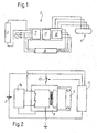
- Fig. 1 shows a block diagram of the device. It comprises an emergency unit 1, a ballast 3 for supplying the fluorescent lamp L in normal supply conditions, in other words when the voltage is supplied from the mains, and a battery 5 for supply in emergency conditions, connectable to the unit 1.
- the emergency unit 1 comprises a battery charger 7 capable of charging the battery 5 when the mains power is present, in other words in normal operating conditions. It also comprises an inverter 9 capable of supplying the lamp L with the power taken from the battery 5 when the mains power is absent, and a control circuit 11 which controls the inverter 9 during operation in emergency conditions.
- the circuit 11 can be of conventional type.
- Fig. 3 shows a circuit for a battery charger capable of supplying a constant recharging current to the battery 5 independently of the voltage of the battery, in other words of the number of cells which make up the battery.
- the battery charger comprises a connection 101 to the electrical mains, a switching power supply unit 103, a connection 105A, 105B to the battery 5, and a resistance 107 connected across the terminals of an operational amplifier 109.
- the output of the amplifier 109 at which there is a signal proportional to the current I charge which the power supply unit 103 supplies to the battery 5 being recharged, is compared by means of a comparator 111 with a reference signal I ref .
- the error signal generated by the comparator 111 is used as a feedback signal for controlling the switching power supply unit 103.
- the control is such that the current I charge is kept at a constant value in time.
- this value is typically 200 mA for batteries with a capacity of 4 Ah, and 100 mA for batteries with a capacity of 2 Ah.
- the circuit of Fig. 3 can be improved to make it possible to use batteries of another type, for example metal-iodide nickel batteries. These batteries require a charging current which is not constant over time, but varies as illustrated in Fig. 4, in other words being equal to a value I 1 for a first charging period, typically of 16 hours, and then equal to a lower value I 2 . To obtain this variation of the charging current it is simply necessary to modify, by means of a suitable timer, the value of the reference signal I ref at the input of the comparator 111.
- a circuit for automatic recognition of the voltage of the battery connected to the charger can be provided, to permit automatic setting of the undervoltage.
- An example of an embodiment of this circuit is shown in Fig. 5. It comprises a time delay switch 121 which is closed after a predetermined time interval, of the order of 30-60 s after the start of the discharge of the battery, in other words after the start of operation of the device in emergency lighting conditions.
- This time interval is necessary because the battery voltage can be read only during the discharge of the battery, and at this stage it is also sufficiently independent of the temperature.
- the manufacturers state that there is a voltage of 1.3-1.35 V per cell after a discharge time of 30-60 s.
- a reference voltage V R1 - V RK is applied to the negative input of each comparator 125.1-125.K.
- the output voltage V 1 -V K of each individual comparator is connected to the non-inverting output of a corresponding amplifier 127.1 - 127.K, whose inverting terminal is connected to earth.
- the outputs of the amplifiers 127.1 - 127.K are connected to corresponding resistors R 1 - R K , where R 1 ⁇ R 2 ⁇ ... ⁇ R K , which, in turn, are connected to a node 129. This is connected through a resistor R C to the voltage V bat and through a resistor R N to earth.
- V R1 N max *V cell - ⁇
- V RK N min *V cell - ⁇
- the final voltage at the node 129 will therefore depend on the number of cells making up the battery, and will be accepted as the minimum voltage (undervoltage) at which the emergency unit will interrupt the discharge current.
- This value is stored by means of the amplifiers 127.1-127.K which form corresponding latch or storage circuits, so that the value of the undervoltage is not modified during operation in emergency conditions, despite the fall in voltage across the terminals of the battery as a result of the gradual running down of the battery.
- this circuit will carry out a battery voltage reading operation consisting of the following stages:
- Figs. 6 to 9A show alternative embodiments of the battery voltage recognition circuit.
- the circuit of Fig. 6 comprises a connection to the battery voltage V bat through a time delay switch, again indicated by 121, and a connection to a reference voltage V cc .
- R N and R C indicate two resistors corresponding to the resistors indicated by the same references in Fig. 5.
- the number 129 indicates the point at which the undervoltage V undervoltage is generated.
- the circuit also comprises two Zener diodes 151.1 and 151.2, two resistors R 1 and R 2 , and two latch circuits, indicated in a general way by 127.1 and 127.2.
- Each of these latch circuits comprises two transistors, of the pnp and npn type respectively, connected in such a way that, when they become conducting, this state of conduction is maintained.
- the arrangement shown here provides two voltage comparison thresholds, but can clearly be multiplied by a multiple arrangement of resistors R 1 , R 2 ... R K , latch circuits 127.1 ... 127.K and Zener diodes 151.1 ... 151.K.
- a variable number of diodes 151 will be caused to conduct, after the switch 121 is closed with a certain delay after the start of operation in emergency conditions, in ways and for reasons similar to those described above with reference to the description of Fig. 5.
- Fig. 7 shows a diagram of a recognition circuit based on the use of a microprocessor 161.
- This has an input connected to an RC branch, comprising a resistor 163 and a capacitor 165, connected to the battery voltage V bat through a transistor 167 and a time delay switch 121 having functions similar to those of the switch 121 of Fig. 5.
- the charging time of the capacitor 165 depends on the battery voltage V bat .
- the capacitor is connected to an input of the microprocessor 161, which changes its level with a delay depending on the charging time of the capacitor 165 and therefore, ultimately, on the battery voltage V bat .
- the delay with which the microprocessor input signal changes to the high value enables the microprocessor 161 to identify the value of the rated battery voltage; according to this value, the microprocessor proceeds to connect a variable number of resistors R 1 ... R K in parallel with the resistor R N .
- the voltage at the point 129 is equal to the undervoltage, and will be defined by formulae (1) and (2) above.
- Fig. 8 shows a circuit diagram which is similar to that of Fig. 7, but makes use of a microprocessor 161 provided with an analog-digital input, in other words one capable of converting an analog signal to a digital signal.
- This input is connected to a branch containing two resistors R a , R b , across whose terminals the battery voltage V bat is applied.
- a time delay switch 121 carries out the functions described above; in other words, it applies the battery voltage V bat after a predetermined interval following the start of operation in emergency conditions.
- the input signal of the microprocessor 161 is converted to a digital signal and compared with a set of values stored in table form in the microprocessor and corresponding to different possible values of the battery voltage.
- the microprocessor 161 can determine which of the resistors R 1 ... R K is to be connected to the node 129, in parallel with the resistor R N , to obtain the undervoltage at the node 129, according to formulae (1) and (2) above.
- Fig. 9 shows a further embodiment of the circuit for recognition of the battery voltage V bat .
- the microprocessor 161 has a PWM output, at which there is a signal having a waveform shown schematically in Fig. 9A.
- the PWM output of the microprocessor 161 is connected, through a resistor R 1 , to a cell RC at whose output there is a voltage equal to the mean value of the PWM signal and corresponding to the undervoltage.
- the value of the duty cycle of the output signal of the microprocessor 161 depends on the value (converted to digital form) of the analog signal at the input of the microprocessor, this analog value being proportional to the battery voltage V bat .
Priority Applications (5)
| Application Number | Priority Date | Filing Date | Title |
|---|---|---|---|
| EP00830719A EP1202429B1 (de) | 2000-10-31 | 2000-10-31 | Notlichteinheit zur Verwendung mit verschiedenen Batterietypen |
| DK00830719T DK1202429T3 (da) | 2000-10-31 | 2000-10-31 | Nödbelysningsenhed til anvendelse med forskellige batterityper |
| DE60021390T DE60021390T2 (de) | 2000-10-31 | 2000-10-31 | Notlichteinheit, verwendbar mit verschiedenen Typen von Batterien |
| ES00830719T ES2245637T3 (es) | 2000-10-31 | 2000-10-31 | Unidad de iluminacion de emergencia utilizable con diferentes tipos de baterias. |
| AT00830719T ATE300114T1 (de) | 2000-10-31 | 2000-10-31 | Notlichteinheit zur verwendung mit verschiedenen batterietypen |
Applications Claiming Priority (1)
| Application Number | Priority Date | Filing Date | Title |
|---|---|---|---|
| EP00830719A EP1202429B1 (de) | 2000-10-31 | 2000-10-31 | Notlichteinheit zur Verwendung mit verschiedenen Batterietypen |
Publications (2)
| Publication Number | Publication Date |
|---|---|
| EP1202429A1 true EP1202429A1 (de) | 2002-05-02 |
| EP1202429B1 EP1202429B1 (de) | 2005-07-20 |
Family
ID=8175532
Family Applications (1)
| Application Number | Title | Priority Date | Filing Date |
|---|---|---|---|
| EP00830719A Expired - Lifetime EP1202429B1 (de) | 2000-10-31 | 2000-10-31 | Notlichteinheit zur Verwendung mit verschiedenen Batterietypen |
Country Status (5)
| Country | Link |
|---|---|
| EP (1) | EP1202429B1 (de) |
| AT (1) | ATE300114T1 (de) |
| DE (1) | DE60021390T2 (de) |
| DK (1) | DK1202429T3 (de) |
| ES (1) | ES2245637T3 (de) |
Cited By (3)
| Publication number | Priority date | Publication date | Assignee | Title |
|---|---|---|---|---|
| EP1496594A1 (de) * | 2003-07-10 | 2005-01-12 | E.R.C. Elettro Radio Costruzioni S.p.A. | Elektronische Stromversorgung für die Notbeleuchtung mit Leuchtstofflampe |
| EP3267558A1 (de) * | 2016-07-06 | 2018-01-10 | Tridonic GmbH & Co. KG | Batterietyperkennung bei notlichtbetriebsgeräten |
| GB2560202A (en) * | 2017-03-01 | 2018-09-05 | Tridonic Gmbh & Co Kg | Emergency lighting converter for different battery technologies |
Families Citing this family (1)
| Publication number | Priority date | Publication date | Assignee | Title |
|---|---|---|---|---|
| ES2382424B1 (es) * | 2010-08-31 | 2013-04-01 | Nicolas Suarez Lencina | Dispositivo convertidor/alimentador de elementos de iluminacion con acumuladores |
Citations (3)
| Publication number | Priority date | Publication date | Assignee | Title |
|---|---|---|---|---|
| US4237385A (en) * | 1977-11-04 | 1980-12-02 | Minitronics Pty, Ltd. | Control of power supply |
| US4571531A (en) * | 1984-04-11 | 1986-02-18 | Lin Ming Hsin | Automatic protective circuit system for emergency lights |
| US6049178A (en) * | 1999-01-19 | 2000-04-11 | Sheu; Tyng-Jeng | Circuit for controlling operation of an emergency exit lamp |
-
2000
- 2000-10-31 EP EP00830719A patent/EP1202429B1/de not_active Expired - Lifetime
- 2000-10-31 ES ES00830719T patent/ES2245637T3/es not_active Expired - Lifetime
- 2000-10-31 AT AT00830719T patent/ATE300114T1/de not_active IP Right Cessation
- 2000-10-31 DE DE60021390T patent/DE60021390T2/de not_active Expired - Lifetime
- 2000-10-31 DK DK00830719T patent/DK1202429T3/da active
Patent Citations (3)
| Publication number | Priority date | Publication date | Assignee | Title |
|---|---|---|---|---|
| US4237385A (en) * | 1977-11-04 | 1980-12-02 | Minitronics Pty, Ltd. | Control of power supply |
| US4571531A (en) * | 1984-04-11 | 1986-02-18 | Lin Ming Hsin | Automatic protective circuit system for emergency lights |
| US6049178A (en) * | 1999-01-19 | 2000-04-11 | Sheu; Tyng-Jeng | Circuit for controlling operation of an emergency exit lamp |
Cited By (5)
| Publication number | Priority date | Publication date | Assignee | Title |
|---|---|---|---|---|
| EP1496594A1 (de) * | 2003-07-10 | 2005-01-12 | E.R.C. Elettro Radio Costruzioni S.p.A. | Elektronische Stromversorgung für die Notbeleuchtung mit Leuchtstofflampe |
| EP3267558A1 (de) * | 2016-07-06 | 2018-01-10 | Tridonic GmbH & Co. KG | Batterietyperkennung bei notlichtbetriebsgeräten |
| GB2560202A (en) * | 2017-03-01 | 2018-09-05 | Tridonic Gmbh & Co Kg | Emergency lighting converter for different battery technologies |
| US10985597B2 (en) | 2017-03-01 | 2021-04-20 | Tridonic Gmbh & Co Kg | Emergency lighting converter |
| GB2560202B (en) * | 2017-03-01 | 2022-01-19 | Tridonic Gmbh & Co Kg | Emergency lighting converter for different battery technologies |
Also Published As
| Publication number | Publication date |
|---|---|
| ATE300114T1 (de) | 2005-08-15 |
| DK1202429T3 (da) | 2005-08-08 |
| EP1202429B1 (de) | 2005-07-20 |
| DE60021390T2 (de) | 2006-05-24 |
| ES2245637T3 (es) | 2006-01-16 |
| DE60021390D1 (de) | 2005-08-25 |
Similar Documents
| Publication | Publication Date | Title |
|---|---|---|
| US7567062B2 (en) | Charging circuit | |
| US7999511B2 (en) | Battery charger | |
| US5990665A (en) | Power circuit | |
| US9071073B2 (en) | Household device continuous battery charger utilizing a constant voltage regulator | |
| US20120104858A1 (en) | Electronic circuit for converting a mains-operated luminaire into an emergency luminaire | |
| EP2244350A2 (de) | Batteriepack | |
| TWI392194B (zh) | 電池充電器 | |
| JPH0550216B2 (de) | ||
| EP0752748B1 (de) | Selbstkonfigurierendes Batterieladegerät mit Mehrfachfunktionen als Versorgungsspannungsregler für batteriebetriebene Geräte | |
| JP2003259560A (ja) | 充電回路 | |
| US5105180A (en) | Combination light unit and battery monitor device | |
| JPH07274413A (ja) | 携帯可能機器用の補助サプライ出力を有する定電流バッテリー充電システム | |
| JP6644443B2 (ja) | 切換装置、それを備える電力ユニットおよびそれを備える電力システム | |
| EP1202429B1 (de) | Notlichteinheit zur Verwendung mit verschiedenen Batterietypen | |
| US6060861A (en) | Car-used spare power system quick charging device | |
| KR19990037303A (ko) | 셀용 충전 전류 어댑터 회로 또는 배터리들 | |
| EP1202428B1 (de) | Notlichteinheit, diese Einheit enthaltende Vorrichtung sowie Steuerungsverfahren | |
| JP3019353B2 (ja) | 充電装置 | |
| EP4117137A1 (de) | Verfahren zur erkennung des typs einer mit einem notstromwandler verbundenen energiespeichervorrichtung | |
| JP2995142B2 (ja) | 直列電池の充電装置 | |
| EP2034587A2 (de) | Verfahren und Anordnung in Verbindung mit einer Notbeleuchtung | |
| JPS596732A (ja) | 充電装置 | |
| JPH0118663B2 (de) | ||
| JP3165119B2 (ja) | 充電回路 | |
| KR920007032Y1 (ko) | 멀티 밧데리의 자동 충전회로 |
Legal Events
| Date | Code | Title | Description |
|---|---|---|---|
| PUAI | Public reference made under article 153(3) epc to a published international application that has entered the european phase |
Free format text: ORIGINAL CODE: 0009012 |
|
| 17P | Request for examination filed |
Effective date: 20010529 |
|
| AK | Designated contracting states |
Kind code of ref document: A1 Designated state(s): AT BE CH CY DE DK ES FI FR GB GR IE IT LI LU MC NL PT SE |
|
| AX | Request for extension of the european patent |
Free format text: AL;LT;LV;MK;RO;SI |
|
| AKX | Designation fees paid |
Free format text: AT BE CH CY DE DK ES FI FR GB GR IE IT LI LU MC NL PT SE |
|
| 17Q | First examination report despatched |
Effective date: 20030808 |
|
| GRAP | Despatch of communication of intention to grant a patent |
Free format text: ORIGINAL CODE: EPIDOSNIGR1 |
|
| GRAS | Grant fee paid |
Free format text: ORIGINAL CODE: EPIDOSNIGR3 |
|
| GRAA | (expected) grant |
Free format text: ORIGINAL CODE: 0009210 |
|
| AK | Designated contracting states |
Kind code of ref document: B1 Designated state(s): AT BE CH CY DE DK ES FI FR GB GR IE IT LI LU MC NL PT SE |
|
| REG | Reference to a national code |
Ref country code: GB Ref legal event code: FG4D |
|
| REG | Reference to a national code |
Ref country code: CH Ref legal event code: EP Ref country code: CH Ref legal event code: NV Representative=s name: BOVARD AG PATENTANWAELTE |
|
| REG | Reference to a national code |
Ref country code: DK Ref legal event code: T3 |
|
| REG | Reference to a national code |
Ref country code: IE Ref legal event code: FG4D |
|
| REF | Corresponds to: |
Ref document number: 60021390 Country of ref document: DE Date of ref document: 20050825 Kind code of ref document: P |
|
| PG25 | Lapsed in a contracting state [announced via postgrant information from national office to epo] |
Ref country code: GR Free format text: LAPSE BECAUSE OF FAILURE TO SUBMIT A TRANSLATION OF THE DESCRIPTION OR TO PAY THE FEE WITHIN THE PRESCRIBED TIME-LIMIT Effective date: 20051020 |
|
| PG25 | Lapsed in a contracting state [announced via postgrant information from national office to epo] |
Ref country code: MC Free format text: LAPSE BECAUSE OF NON-PAYMENT OF DUE FEES Effective date: 20051031 Ref country code: LU Free format text: LAPSE BECAUSE OF NON-PAYMENT OF DUE FEES Effective date: 20051031 Ref country code: CY Free format text: LAPSE BECAUSE OF FAILURE TO SUBMIT A TRANSLATION OF THE DESCRIPTION OR TO PAY THE FEE WITHIN THE PRESCRIBED TIME-LIMIT Effective date: 20051031 |
|
| PG25 | Lapsed in a contracting state [announced via postgrant information from national office to epo] |
Ref country code: IE Free format text: LAPSE BECAUSE OF NON-PAYMENT OF DUE FEES Effective date: 20051101 |
|
| REG | Reference to a national code |
Ref country code: SE Ref legal event code: TRGR |
|
| PG25 | Lapsed in a contracting state [announced via postgrant information from national office to epo] |
Ref country code: PT Free format text: LAPSE BECAUSE OF FAILURE TO SUBMIT A TRANSLATION OF THE DESCRIPTION OR TO PAY THE FEE WITHIN THE PRESCRIBED TIME-LIMIT Effective date: 20051221 |
|
| REG | Reference to a national code |
Ref country code: ES Ref legal event code: FG2A Ref document number: 2245637 Country of ref document: ES Kind code of ref document: T3 |
|
| PLBE | No opposition filed within time limit |
Free format text: ORIGINAL CODE: 0009261 |
|
| STAA | Information on the status of an ep patent application or granted ep patent |
Free format text: STATUS: NO OPPOSITION FILED WITHIN TIME LIMIT |
|
| 26N | No opposition filed |
Effective date: 20060421 |
|
| GBPC | Gb: european patent ceased through non-payment of renewal fee |
Effective date: 20051031 |
|
| REG | Reference to a national code |
Ref country code: GB Ref legal event code: 728V |
|
| REG | Reference to a national code |
Ref country code: IE Ref legal event code: MM4A |
|
| EN | Fr: translation not filed | ||
| PG25 | Lapsed in a contracting state [announced via postgrant information from national office to epo] |
Ref country code: FR Free format text: LAPSE BECAUSE OF FAILURE TO SUBMIT A TRANSLATION OF THE DESCRIPTION OR TO PAY THE FEE WITHIN THE PRESCRIBED TIME-LIMIT Effective date: 20060915 |
|
| REG | Reference to a national code |
Ref country code: GB Ref legal event code: 728Y |
|
| PG25 | Lapsed in a contracting state [announced via postgrant information from national office to epo] |
Ref country code: FR Free format text: LAPSE BECAUSE OF FAILURE TO SUBMIT A TRANSLATION OF THE DESCRIPTION OR TO PAY THE FEE WITHIN THE PRESCRIBED TIME-LIMIT Effective date: 20051031 |
|
| PG25 | Lapsed in a contracting state [announced via postgrant information from national office to epo] |
Ref country code: FR Free format text: LAPSE BECAUSE OF FAILURE TO SUBMIT A TRANSLATION OF THE DESCRIPTION OR TO PAY THE FEE WITHIN THE PRESCRIBED TIME-LIMIT Effective date: 20050720 |
|
| PGFP | Annual fee paid to national office [announced via postgrant information from national office to epo] |
Ref country code: AT Payment date: 20091022 Year of fee payment: 10 Ref country code: CH Payment date: 20091003 Year of fee payment: 10 Ref country code: SE Payment date: 20091026 Year of fee payment: 10 Ref country code: FI Payment date: 20091027 Year of fee payment: 10 Ref country code: ES Payment date: 20091023 Year of fee payment: 10 Ref country code: DK Payment date: 20091010 Year of fee payment: 10 |
|
| PGFP | Annual fee paid to national office [announced via postgrant information from national office to epo] |
Ref country code: NL Payment date: 20091020 Year of fee payment: 10 |
|
| PGFP | Annual fee paid to national office [announced via postgrant information from national office to epo] |
Ref country code: GB Payment date: 20091028 Year of fee payment: 10 Ref country code: IT Payment date: 20091029 Year of fee payment: 10 |
|
| PGFP | Annual fee paid to national office [announced via postgrant information from national office to epo] |
Ref country code: BE Payment date: 20091020 Year of fee payment: 10 |
|
| PGFP | Annual fee paid to national office [announced via postgrant information from national office to epo] |
Ref country code: DE Payment date: 20091218 Year of fee payment: 10 |
|
| REG | Reference to a national code |
Ref country code: CH Ref legal event code: PFA Owner name: MAGNETEK S.P.A. Free format text: MAGNETEK S.P.A.#81, VIA SETTORE NORD EST#52028 TERRANUOVA BRACCIOLINI (AR) (IT) -TRANSFER TO- MAGNETEK S.P.A.#81, VIA SETTORE NORD EST#52028 TERRANUOVA BRACCIOLINI (AR) (IT) |
|
| BERE | Be: lapsed |
Owner name: *MAGNETEK S.P.A. Effective date: 20101031 |
|
| REG | Reference to a national code |
Ref country code: NL Ref legal event code: V1 Effective date: 20110501 |
|
| REG | Reference to a national code |
Ref country code: DK Ref legal event code: EBP |
|
| REG | Reference to a national code |
Ref country code: CH Ref legal event code: PL |
|
| REG | Reference to a national code |
Ref country code: SE Ref legal event code: EUG |
|
| GBPC | Gb: european patent ceased through non-payment of renewal fee |
Effective date: 20101031 |
|
| PG25 | Lapsed in a contracting state [announced via postgrant information from national office to epo] |
Ref country code: CH Free format text: LAPSE BECAUSE OF NON-PAYMENT OF DUE FEES Effective date: 20101031 Ref country code: LI Free format text: LAPSE BECAUSE OF NON-PAYMENT OF DUE FEES Effective date: 20101031 |
|
| REG | Reference to a national code |
Ref country code: DE Ref legal event code: R119 Ref document number: 60021390 Country of ref document: DE Effective date: 20110502 |
|
| PG25 | Lapsed in a contracting state [announced via postgrant information from national office to epo] |
Ref country code: AT Free format text: LAPSE BECAUSE OF NON-PAYMENT OF DUE FEES Effective date: 20101031 Ref country code: FI Free format text: LAPSE BECAUSE OF NON-PAYMENT OF DUE FEES Effective date: 20101031 Ref country code: GB Free format text: LAPSE BECAUSE OF NON-PAYMENT OF DUE FEES Effective date: 20101031 Ref country code: BE Free format text: LAPSE BECAUSE OF NON-PAYMENT OF DUE FEES Effective date: 20101031 Ref country code: NL Free format text: LAPSE BECAUSE OF NON-PAYMENT OF DUE FEES Effective date: 20110501 |
|
| PG25 | Lapsed in a contracting state [announced via postgrant information from national office to epo] |
Ref country code: SE Free format text: LAPSE BECAUSE OF NON-PAYMENT OF DUE FEES Effective date: 20101101 |
|
| PG25 | Lapsed in a contracting state [announced via postgrant information from national office to epo] |
Ref country code: DK Free format text: LAPSE BECAUSE OF NON-PAYMENT OF DUE FEES Effective date: 20101031 |
|
| REG | Reference to a national code |
Ref country code: ES Ref legal event code: FD2A Effective date: 20111121 |
|
| PG25 | Lapsed in a contracting state [announced via postgrant information from national office to epo] |
Ref country code: IT Free format text: LAPSE BECAUSE OF NON-PAYMENT OF DUE FEES Effective date: 20101031 |
|
| PG25 | Lapsed in a contracting state [announced via postgrant information from national office to epo] |
Ref country code: ES Free format text: LAPSE BECAUSE OF NON-PAYMENT OF DUE FEES Effective date: 20101101 |
|
| PG25 | Lapsed in a contracting state [announced via postgrant information from national office to epo] |
Ref country code: DE Free format text: LAPSE BECAUSE OF NON-PAYMENT OF DUE FEES Effective date: 20110502 |