EP1202409B1 - Tuning a laser - Google Patents
Tuning a laser Download PDFInfo
- Publication number
- EP1202409B1 EP1202409B1 EP01113372A EP01113372A EP1202409B1 EP 1202409 B1 EP1202409 B1 EP 1202409B1 EP 01113372 A EP01113372 A EP 01113372A EP 01113372 A EP01113372 A EP 01113372A EP 1202409 B1 EP1202409 B1 EP 1202409B1
- Authority
- EP
- European Patent Office
- Prior art keywords
- tilting
- tuning
- laser
- dispersion
- moving
- Prior art date
- Legal status (The legal status is an assumption and is not a legal conclusion. Google has not performed a legal analysis and makes no representation as to the accuracy of the status listed.)
- Expired - Lifetime
Links
- 239000006185 dispersion Substances 0.000 claims description 41
- 238000000034 method Methods 0.000 claims description 12
- 238000012545 processing Methods 0.000 claims description 2
- 230000003287 optical effect Effects 0.000 description 5
- 238000012937 correction Methods 0.000 description 4
- 238000004519 manufacturing process Methods 0.000 description 2
- 238000012360 testing method Methods 0.000 description 2
- 238000004891 communication Methods 0.000 description 1
- 230000001419 dependent effect Effects 0.000 description 1
- 230000000694 effects Effects 0.000 description 1
Images

Classifications
-
- H—ELECTRICITY
- H01—ELECTRIC ELEMENTS
- H01S—DEVICES USING THE PROCESS OF LIGHT AMPLIFICATION BY STIMULATED EMISSION OF RADIATION [LASER] TO AMPLIFY OR GENERATE LIGHT; DEVICES USING STIMULATED EMISSION OF ELECTROMAGNETIC RADIATION IN WAVE RANGES OTHER THAN OPTICAL
- H01S5/00—Semiconductor lasers
- H01S5/10—Construction or shape of the optical resonator, e.g. extended or external cavity, coupled cavities, bent-guide, varying width, thickness or composition of the active region
- H01S5/14—External cavity lasers
- H01S5/141—External cavity lasers using a wavelength selective device, e.g. a grating or etalon
- H01S5/143—Littman-Metcalf configuration, e.g. laser - grating - mirror
Definitions
- the present invention relates to laser tuning.
- Littman cavities can be used as external cavities to allow single-mode tuning of the laser.
- the geometry of these cavities is known, see e.g.: Liu and Littman, "Novel geometry for single-mode scanning of tunable lasers", Optical Society of America, 1981.
- the advantage of the Littman cavity is that it is possible to tune the wavelength and the optical length of the cavity at the same time by changing only one parameter of the geometry, i.e. the tuning element.
- tunable lasers in particular based on the Littman geometry, can be found e.g. in US-A-5,867,512, DE-A-19509922, Wenz H. et al: "Continuously Tunable Diode Laser” in 'Laser und Optoelekronik' (Fachverlag GmbH, Stuttgart, DE, Vol.28 No.1, p.58-62, Feb. 1, 1996, XP000775842, ISSN: 0722-9003), Wandt D.
- the Littman geometry is extremely sensible to deviations of the real geometry with respect to the perfect Littman configuration. This does impose severe requirements on the rotation mount for the tuning element of the Littman cavity. Smallest errors in the positioning of the pivot axis of the tuning element reduce the full feedback tuning range of a tuning element of the cavity heavily. This requires costly precision when manufacturing and maintaining such tunable lasers.
- An advantage of the present invention is the provision of a tunable laser which autonomously and easily compensates for deviations, e.g. an inclination of the real position of the pivot axis of the tuning element with respect to the theoretical perfect position of the pivot axis, so that over the tuning range of the tuning element it is possible to have the full feedback of the tuning element.
- the compensation is sufficient to keep the feedback power of the tuning element at least near its maximum within a predetermined tuning range of the tuning element it is possible to have the full feedback of the tuning element.
- the compensation is sufficient to keep the feedback power of the tuning element at least near its maximum within a predetermined tuning range of the tuning element.
- the compensation is done by moving the dispersion element, preferably along a predetermined path, corresponding with the rotation of the tuning element. Therefore, method and apparatus for tuning of lasers according to the present invention avoid the aforementioned problems of the prior art and provide a tunable laser with a wide full feedback tuning range without heavy duties to the precision when manufacturing and maintaining such laser.
- the moving of the dispersion element is done simultaneously with the rotation of the tuning element. This achieves an online correction, so that always the correct position of the dispersion element for the full feedback of the tuning element is guaranteed.
- the correction is done by moving the dispersion element by tilting it by a predetermined angle about a predetermined tilting axis.
- This way of correction can be easily implemented in the inventive apparatus, e.g. by using a bimorph type piezo-electric element that can precisely move the respective tuning element of the laser.
- the correction is done by a dispersion element which is a diffraction grating and in which the tilting axis is at least not parallel, more preferred perpendicular, to the axes of the rules of the grating. This positioning serves for maximum efficiency of the inventive method and apparatus.
- the method further comprises steps for at least approximately evaluating a function which determines the tilting angle of the dispersion element for keeping the feedback power of the tuning element at least near its maximum within a predetermined tuning range of the tuning element per rotating angle of the tuning element.
- This calculation is done by: step a: rotating the tuning element to tune the laser to one wavelength, step b: tilting the dispersion element until the feedback power is substantially at its maximum, repeating steps a and b at least one time at another wavelength, using the at least two values of tilting angle per rotating angle to evaluate an approximation of the function which determines the tilting angle per rotating angle. This can be done fast and easy so that a quick adjustment of the apparatus for full feedback of the tuning element is achieved.
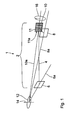
- Fig. 1 shows a schematic view of a first embodiment 1 of the apparatus of the present invention.
- the apparatus 1 of Fig. 1 comprises an external cavity 2 in which laser light provided by an active medium (not shown), e.g. a laser diode, can resonate to provide a laser beam 4.
- the beam 4 travels in the cavity 2 along a path between a cavity end element 6 and a tuning element 8 of the external cavity 2.
- the cavity end element 6 arid the tuning element 8 both providing a high reflective mirror.
- the apparatus 1 further comprises a dispersion element 10 introduced in the path of the beam 4 for selecting at least one longitudinal mode of the laser.
- the dispersion element comprises a grating 11 having rules 11a.
- the tuning element 8 can be rotated by an actuator (not shown) according to arrow 12 about a pivot axis 14 to tune the laser.
- the pivot axis 14 is theoretically defined by the intersection of the surface plane (indicated by line 6a) of the cavity end element 6, the surface plane (indicated by line 10a) of the dispersion element 10 and the surface plane (indicated by line 8a) of the tuning element 8.
- the dispersion element 10 is mounted on one end of an electrically driven bimorph type piezo-electric element (not shown) which serves as the moving element of the invention.
- One end of the bimorph type piezo-electric element is freely slewable whereas the other end of the bimorph type piezo-electric element is fixed relative to the cavity 2.
- the bimorph type piezo-electric element allows moving the dispersion element 10 corresponding, preferably simultaneously, with the rotation of the tuning element 8 to compensate an inclination between the real position of the pivot axis 14 and the theoretically defined position. This is done preferably by moving the dispersion element 10 along such a predetermined path that the compensation is sufficient to keep the feedback power of the tuning element 8 near its maximum within a predetermined tuning range of the tuning element 8.
- Moving the dispersion element 10 in this embodiment means tilting the dispersion element 10 according to arrow 16 by a predetermined angle (for the predetermination of the angle see below) about the tilting axis 10a which is substantially perpendicular to the rules 11a and lies substantially in the plane of the grating 11.
- the apparatus of Fig. 1 preferably further comprises as a measuring device a wire strain gauge (not shown) for measuring the tilting angle 16 of the tilting of the dispersion element 10 and to output a measured value of the tilting angle 16, a comparator (not shown) connected with the wire strain gauge for comparing the measured value of the tilting angle 16 with the predetermined value of the tilting angle 16 and to output a signal indicating a difference between the measured value and the predetermined value of the tilting angle 16, a controller (not shown) connected with the output of the comparator and with the moving element for adjusting the tilting angle 16 when the comparator has detected a difference between the measured value and the predetermined value.
- a wire strain gauge (not shown) for measuring the tilting angle 16 of the tilting of the dispersion element 10 and to output a measured value of the tilting angle 16
- a comparator (not shown) connected with the wire strain gauge for comparing the measured value of the tilting angle 16 with the predetermined value of the tilting angle 16 and to output a signal
- step a rotating the tuning element 8 to tune the laser to one wavelength
- step b tilting the dispersion element 10 until the feedback power is substantially at its maximum
- step b tilting the dispersion element 10 until the feedback power is substantially at its maximum
- steps a and b at least one time at another wavelength
- the approximation can be done by known approximation methods. The more repeats of steps a and b are performed the more exact is the predetermination.
- Fig. 2 shows a schematic view of a second embodiment 100 of the apparatus of the present invention.
- embodiment 1 of Fig. 1 and embodiment 100 of Fig.2 The only difference between embodiment 1 of Fig. 1 and embodiment 100 of Fig.2 is that of the dispersion element 10 has a different tilting axis 110a.
- the tilting axis 110a of embodiment 100 is perpendicular both to the plane of the grating 11 and to the rules of the grating 11 of the dispersion element 10. Accordingly, the dispersion element 10 can be tilted according to arrow 116 of Fig. 2.
- the inventive effect is reached with embodiment 100, also.
- the predetermination of the tilting angle 116 is done corresponding to the aforedescribed method for predetermination of the tilting angle 16 of the embodiment of Fig. 1.
- the positioning of the axes 14, 6a, 8a, 10a, 110a according to the Fig. 1 and 2 only show the ideal case of the positioning of the axes 14, 6a, 8a, 10a, 110a.
- the axes 14, 6a, 8a, 10a, 110a however can be positioned in another way, i.e. in other angles or positions as shown in Fig. 1 and 2, e.g. in other angles relative to the cavity end element 6, the tuning element 8 and the dispersion element 10.
- the axes 14, 6a, 8a, 10a, 110a can be combined with each other.
Landscapes
- Physics & Mathematics (AREA)
- Condensed Matter Physics & Semiconductors (AREA)
- General Physics & Mathematics (AREA)
- Electromagnetism (AREA)
- Optics & Photonics (AREA)
- Lasers (AREA)
Priority Applications (3)
| Application Number | Priority Date | Filing Date | Title |
|---|---|---|---|
| EP01113372A EP1202409B1 (en) | 2001-06-01 | 2001-06-01 | Tuning a laser |
| US10/101,044 US6807217B2 (en) | 2001-06-01 | 2002-03-19 | Tuning a laser |
| JP2002161459A JP2003023197A (ja) | 2001-06-01 | 2002-06-03 | レーザ同調方法及びレーザ同調装置 |
Applications Claiming Priority (1)
| Application Number | Priority Date | Filing Date | Title |
|---|---|---|---|
| EP01113372A EP1202409B1 (en) | 2001-06-01 | 2001-06-01 | Tuning a laser |
Publications (2)
| Publication Number | Publication Date |
|---|---|
| EP1202409A1 EP1202409A1 (en) | 2002-05-02 |
| EP1202409B1 true EP1202409B1 (en) | 2003-04-16 |
Family
ID=8177613
Family Applications (1)
| Application Number | Title | Priority Date | Filing Date |
|---|---|---|---|
| EP01113372A Expired - Lifetime EP1202409B1 (en) | 2001-06-01 | 2001-06-01 | Tuning a laser |
Country Status (3)
| Country | Link |
|---|---|
| US (1) | US6807217B2 (enExample) |
| EP (1) | EP1202409B1 (enExample) |
| JP (1) | JP2003023197A (enExample) |
Families Citing this family (12)
| Publication number | Priority date | Publication date | Assignee | Title |
|---|---|---|---|---|
| US6414973B1 (en) * | 1999-08-31 | 2002-07-02 | Ruey-Jen Hwu | High-power blue and green light laser generation from high powered diode lasers |
| US8174436B2 (en) * | 2002-07-08 | 2012-05-08 | American Underwater Products, Inc. | Dive computer with global positioning system receiver |
| US20070104231A1 (en) * | 2002-08-30 | 2007-05-10 | Jochen Schwarz | Wavelength tunable resonator with a prism |
| EP1330000A1 (en) * | 2002-12-06 | 2003-07-23 | Agilent Technologies Inc | Operating point determination for mode-selection laser |
| JP4073886B2 (ja) | 2004-03-30 | 2008-04-09 | アンリツ株式会社 | 可変波長光源 |
| EP1628374A1 (en) | 2004-08-18 | 2006-02-22 | Agilent Technologies, Inc. | External cavity laser with multiple stabilized modes |
| US20070160325A1 (en) * | 2006-01-11 | 2007-07-12 | Hyungbin Son | Angle-tunable transmissive grating |
| US7903704B2 (en) * | 2006-06-23 | 2011-03-08 | Pranalytica, Inc. | Tunable quantum cascade lasers and photoacoustic detection of trace gases, TNT, TATP and precursors acetone and hydrogen peroxide |
| CN102106188B (zh) * | 2008-07-21 | 2015-02-18 | 皇家飞利浦电子股份有限公司 | 安装灯具的方法和应用该方法的灯具 |
| US8023549B2 (en) * | 2009-09-30 | 2011-09-20 | Nichia Corporation | Tuning method of external cavity laser diode, variable wavelength laser module, and program of external cavity laser diode tuning |
| US9331455B1 (en) * | 2012-01-23 | 2016-05-03 | Nlight Photonics Corporation | Frequency locked diode laser devices exhibiting low power penalty |
| US9608408B2 (en) | 2012-09-26 | 2017-03-28 | Pranalytica, Inc. | Long wavelength quantum cascade lasers based on high strain composition |
Family Cites Families (10)
| Publication number | Priority date | Publication date | Assignee | Title |
|---|---|---|---|---|
| US4229710A (en) * | 1977-10-21 | 1980-10-21 | Itamar Shoshan | Wavelength selector for tunable laser |
| US5319668A (en) * | 1992-09-30 | 1994-06-07 | New Focus, Inc. | Tuning system for external cavity diode laser |
| DE19509922C2 (de) * | 1995-03-18 | 2001-02-22 | Joachim Sacher | Abstimmvorrichtung für einen Halbleiterlaser mit externem Resonator |
| JPH09260753A (ja) * | 1996-03-25 | 1997-10-03 | Ando Electric Co Ltd | 外部共振器型波長可変光源 |
| US5867512A (en) * | 1997-02-10 | 1999-02-02 | Sacher; Joachim | Tuning arrangement for a semiconductor diode laser with an external resonator |
| DE19832750C2 (de) * | 1998-07-21 | 2000-06-08 | Lpkf Laser & Electronics Gmbh | Justierbares System eines Diodenlasers mit externem Resonator in der Littmann-Konfiguration |
| WO2000016453A1 (en) * | 1998-09-11 | 2000-03-23 | New Focus, Inc. | Tunable laser |
| US6879619B1 (en) * | 1999-07-27 | 2005-04-12 | Intel Corporation | Method and apparatus for filtering an optical beam |
| US6366592B1 (en) * | 2000-10-25 | 2002-04-02 | Axsun Technologies, Inc. | Stepped etalon semiconductor laser wavelength locker |
| DE60100100T2 (de) * | 2001-06-01 | 2003-11-13 | Agilent Technologies, Inc. (N.D.Ges.D.Staates Delaware) | Laserdurchstimmung |
-
2001
- 2001-06-01 EP EP01113372A patent/EP1202409B1/en not_active Expired - Lifetime
-
2002
- 2002-03-19 US US10/101,044 patent/US6807217B2/en not_active Expired - Fee Related
- 2002-06-03 JP JP2002161459A patent/JP2003023197A/ja active Pending
Also Published As
| Publication number | Publication date |
|---|---|
| US20020181537A1 (en) | 2002-12-05 |
| EP1202409A1 (en) | 2002-05-02 |
| JP2003023197A (ja) | 2003-01-24 |
| US6807217B2 (en) | 2004-10-19 |
Similar Documents
| Publication | Publication Date | Title |
|---|---|---|
| EP1202409B1 (en) | Tuning a laser | |
| JP2836566B2 (ja) | 波長安定化狭帯域エキシマレーザ装置 | |
| CN103339808B (zh) | 激光表征系统和过程 | |
| EP1202408B1 (en) | Tuning a laser | |
| EP0341315B1 (en) | Method of stabilizing laser wavelength and laser device with stabilized wavelength | |
| EP0411635A2 (en) | Method of stabilizing the laser beam and apparatus utilizing the same | |
| US6324193B1 (en) | Continuously wavelength-tunable monomode laser source | |
| EP1734624A1 (en) | External cavity laser with flexure tuning element | |
| EP1502337B1 (en) | Wavelength tunable laser source with parameter correction | |
| US6763044B2 (en) | Tuning a laser | |
| US20020141458A1 (en) | Wavelength-variable light source | |
| EP1671403B1 (en) | Angular laser control | |
| EP1508188B1 (en) | Laser cavity with variable dispersion element | |
| US20020054734A1 (en) | Wavelength monitor apparatus and wavelength stabilizing light source | |
| JP2004500698A (ja) | リットマン配置の外部共振器を備えたダイオードレーザーの調節可能なシステム | |
| US20250279628A1 (en) | Tunable laser with tilt tuned interference filter with blocking filter | |
| US20240019363A1 (en) | Integrated cat's-eye tunable laser spectroscopy system and method | |
| EP3622592A1 (en) | External optical feedback element for tuning a multi-wavelenght gas laser | |
| EP1330000A1 (en) | Operating point determination for mode-selection laser |
Legal Events
| Date | Code | Title | Description |
|---|---|---|---|
| PUAI | Public reference made under article 153(3) epc to a published international application that has entered the european phase |
Free format text: ORIGINAL CODE: 0009012 |
|
| AK | Designated contracting states |
Kind code of ref document: A1 Designated state(s): AT BE CH CY DE DK ES FI FR GB GR IE IT LI LU MC NL PT SE TR Kind code of ref document: A1 Designated state(s): DE FR GB |
|
| AX | Request for extension of the european patent |
Free format text: AL;LT;LV;MK;RO;SI |
|
| 17P | Request for examination filed |
Effective date: 20020302 |
|
| GRAH | Despatch of communication of intention to grant a patent |
Free format text: ORIGINAL CODE: EPIDOS IGRA |
|
| GRAH | Despatch of communication of intention to grant a patent |
Free format text: ORIGINAL CODE: EPIDOS IGRA |
|
| AKX | Designation fees paid |
Free format text: DE FR GB |
|
| GRAA | (expected) grant |
Free format text: ORIGINAL CODE: 0009210 |
|
| AK | Designated contracting states |
Designated state(s): FR GB |
|
| RBV | Designated contracting states (corrected) |
Designated state(s): FR GB |
|
| REG | Reference to a national code |
Ref country code: GB Ref legal event code: FG4D |
|
| REG | Reference to a national code |
Ref country code: DE Ref legal event code: 8566 |
|
| REG | Reference to a national code |
Ref country code: IE Ref legal event code: FG4D |
|
| ET | Fr: translation filed | ||
| PLBE | No opposition filed within time limit |
Free format text: ORIGINAL CODE: 0009261 |
|
| STAA | Information on the status of an ep patent application or granted ep patent |
Free format text: STATUS: NO OPPOSITION FILED WITHIN TIME LIMIT |
|
| 26N | No opposition filed |
Effective date: 20040119 |
|
| REG | Reference to a national code |
Ref country code: IE Ref legal event code: MM4A |
|
| PGFP | Annual fee paid to national office [announced via postgrant information from national office to epo] |
Ref country code: FR Payment date: 20060620 Year of fee payment: 6 |
|
| PGFP | Annual fee paid to national office [announced via postgrant information from national office to epo] |
Ref country code: GB Payment date: 20060626 Year of fee payment: 6 |
|
| GBPC | Gb: european patent ceased through non-payment of renewal fee |
Effective date: 20070601 |
|
| REG | Reference to a national code |
Ref country code: FR Ref legal event code: ST Effective date: 20080229 |
|
| PG25 | Lapsed in a contracting state [announced via postgrant information from national office to epo] |
Ref country code: GB Free format text: LAPSE BECAUSE OF NON-PAYMENT OF DUE FEES Effective date: 20070601 |
|
| PG25 | Lapsed in a contracting state [announced via postgrant information from national office to epo] |
Ref country code: FR Free format text: LAPSE BECAUSE OF NON-PAYMENT OF DUE FEES Effective date: 20070702 |