EP1628374A1 - External cavity laser with multiple stabilized modes - Google Patents
External cavity laser with multiple stabilized modes Download PDFInfo
- Publication number
- EP1628374A1 EP1628374A1 EP04103969A EP04103969A EP1628374A1 EP 1628374 A1 EP1628374 A1 EP 1628374A1 EP 04103969 A EP04103969 A EP 04103969A EP 04103969 A EP04103969 A EP 04103969A EP 1628374 A1 EP1628374 A1 EP 1628374A1
- Authority
- EP
- European Patent Office
- Prior art keywords
- external cavity
- mode
- fsr1
- fsr2
- selecting filter
- Prior art date
- Legal status (The legal status is an assumption and is not a legal conclusion. Google has not performed a legal analysis and makes no representation as to the accuracy of the status listed.)
- Withdrawn
Links
- 230000003595 spectral effect Effects 0.000 claims abstract description 51
- 230000003287 optical effect Effects 0.000 claims abstract description 42
- 238000001514 detection method Methods 0.000 claims description 21
- 238000006073 displacement reaction Methods 0.000 claims description 14
- BJQHLKABXJIVAM-UHFFFAOYSA-N bis(2-ethylhexyl) phthalate Chemical compound CCCCC(CC)COC(=O)C1=CC=CC=C1C(=O)OCC(CC)CCCC BJQHLKABXJIVAM-UHFFFAOYSA-N 0.000 claims description 11
- 230000000704 physical effect Effects 0.000 claims description 6
- 230000007613 environmental effect Effects 0.000 claims description 5
- 238000005259 measurement Methods 0.000 claims description 5
- 238000000034 method Methods 0.000 claims description 4
- 238000001914 filtration Methods 0.000 claims description 3
- 230000000903 blocking effect Effects 0.000 claims description 2
- 238000012545 processing Methods 0.000 claims description 2
- 238000001228 spectrum Methods 0.000 description 19
- 238000010586 diagram Methods 0.000 description 9
- 230000005540 biological transmission Effects 0.000 description 4
- 239000006185 dispersion Substances 0.000 description 4
- 238000000411 transmission spectrum Methods 0.000 description 4
- 239000008186 active pharmaceutical agent Substances 0.000 description 3
- 238000012935 Averaging Methods 0.000 description 2
- 230000008901 benefit Effects 0.000 description 2
- 230000008859 change Effects 0.000 description 2
- 238000012885 constant function Methods 0.000 description 2
- 239000000463 material Substances 0.000 description 2
- 230000010363 phase shift Effects 0.000 description 2
- 230000005855 radiation Effects 0.000 description 2
- 238000002310 reflectometry Methods 0.000 description 2
- 238000010521 absorption reaction Methods 0.000 description 1
- 230000032683 aging Effects 0.000 description 1
- 238000010276 construction Methods 0.000 description 1
- 230000007423 decrease Effects 0.000 description 1
- 230000001419 dependent effect Effects 0.000 description 1
- 238000013461 design Methods 0.000 description 1
- 230000005684 electric field Effects 0.000 description 1
- 238000011156 evaluation Methods 0.000 description 1
- 239000000835 fiber Substances 0.000 description 1
- 238000012423 maintenance Methods 0.000 description 1
- 230000000737 periodic effect Effects 0.000 description 1
- 230000009467 reduction Effects 0.000 description 1
- 230000004044 response Effects 0.000 description 1
- 239000004065 semiconductor Substances 0.000 description 1
Images


Classifications
-
- H—ELECTRICITY
- H01—ELECTRIC ELEMENTS
- H01S—DEVICES USING THE PROCESS OF LIGHT AMPLIFICATION BY STIMULATED EMISSION OF RADIATION [LASER] TO AMPLIFY OR GENERATE LIGHT; DEVICES USING STIMULATED EMISSION OF ELECTROMAGNETIC RADIATION IN WAVE RANGES OTHER THAN OPTICAL
- H01S5/00—Semiconductor lasers
- H01S5/10—Construction or shape of the optical resonator, e.g. extended or external cavity, coupled cavities, bent-guide, varying width, thickness or composition of the active region
- H01S5/14—External cavity lasers
- H01S5/141—External cavity lasers using a wavelength selective device, e.g. a grating or etalon
-
- H—ELECTRICITY
- H01—ELECTRIC ELEMENTS
- H01S—DEVICES USING THE PROCESS OF LIGHT AMPLIFICATION BY STIMULATED EMISSION OF RADIATION [LASER] TO AMPLIFY OR GENERATE LIGHT; DEVICES USING STIMULATED EMISSION OF ELECTROMAGNETIC RADIATION IN WAVE RANGES OTHER THAN OPTICAL
- H01S5/00—Semiconductor lasers
- H01S5/06—Arrangements for controlling the laser output parameters, e.g. by operating on the active medium
- H01S5/068—Stabilisation of laser output parameters
- H01S5/0683—Stabilisation of laser output parameters by monitoring the optical output parameters
- H01S5/0687—Stabilising the frequency of the laser
-
- H—ELECTRICITY
- H01—ELECTRIC ELEMENTS
- H01S—DEVICES USING THE PROCESS OF LIGHT AMPLIFICATION BY STIMULATED EMISSION OF RADIATION [LASER] TO AMPLIFY OR GENERATE LIGHT; DEVICES USING STIMULATED EMISSION OF ELECTROMAGNETIC RADIATION IN WAVE RANGES OTHER THAN OPTICAL
- H01S5/00—Semiconductor lasers
- H01S5/10—Construction or shape of the optical resonator, e.g. extended or external cavity, coupled cavities, bent-guide, varying width, thickness or composition of the active region
- H01S5/1039—Details on the cavity length
Definitions
- the present invention relates to external cavity lasers.
- An external cavity laser comprises a cavity that provides an optical path so that a laser beam, stimulated by a gain or active medium, can resonate.
- the optical spectrum of an external cavity laser is limited by the spectral region over which the gain medium yields optical gain.
- the laser radiation has certain allowed spectral modes, also referred to as longitudinal modes.
- the spectral modes correspond to different distinct wavelengths or frequencies of the light.
- the allowed radiation spectrum in a laser cavity thus is a discrete distribution of modal frequencies limited by the gain curve. Examples of external cavity lasers can be found in US-A- 5,331,651, EP-A-0 552 394 and in EP-A-1 202 409.
- US 5,331,651 discloses a tuneable Fabry Perot etalon to be used in an external cavity laser comprising a semiconductor laser chip and adjustable diffraction grating.
- the adjustable diffraction grating is used for a coarse measurement of the laser output wavelength and the etalon is used for the fine adjustment.
- a laser apparatus comprising an external cavity that provides an optical path for generating a laser beam stimulated by a gain medium, the external cavity having a first spectral characteristic, and further comprises a mode-selecting filter mounted within the optical path, having a second spectral characteristic.
- the spectral response of such an arrangement corresponds to a multiplication of the spectra of the cavity and the mode-selecting filter(s).
- the first characteristic and the second characteristic are adjusted to each other, e.g. by design, by open loop control or by closed loop control, so that the laser beam comprises at least two selected modes.
- the selected modes substantially comprise all the same optical power.
- the laser apparatus comprises an adjustment device to tune (for re-adjusting or changing) the first characteristics and the second characteristics.
- the laser apparatus comprises measurement means for determining a physical property related to the laser apparatus, e.g. the optical power of the laser beam and a feed back loop to the adjustment device. On the base of the measured physical property, a control signal is generated to control the adjustment device such, that a matching of the external cavity and the mode-selecting filter is kept.
- the invention has the advantage that variations of laser apparatus characteristics over the time, e.g. due to environmental conditions or to aging, leading to a mismatch of the spectral characteristics and thus resulting in a reduced modal power and instabilities of optical power can be avoided.
- the adjustment means are adapted to adjust the first characteristics and the second characteristics by changing the geometry of the external cavity, e.g. the cavity length or the refractive index within the optical path and/or the geometry of the mode-selecting filter. It is also possible to adjust the characteristics by changing the refractive index of the material conducting the laser beam.
- the mode-selecting filter consists of at least one periodical filter, so that the first characteristics and the second characteristics can be expressed as a first spectral range (FSR1) of the external cavity and a second free spectral range (FSR2) of the mode-selecting filter respectively.
- the adjustment means are adapted to adjust said characteristics such that the ratio between the first free spectral range (FSR2) and the second free spectral (FSR1) range is substantially a rational number, especially a natural number.
- an opto-electrical converter is comprised for receiving a portion of the laser beam, that can be coupled out by means of a high reflectivity mirror at one end of the external cavity that reflects the main portion of the resonating laser beam and transmits a small portion (e.g. 5%) to the opto-electrical converter.
- the opto-electrical converter generates an electrical detection signal that is proportional to the actual power of the laser beam.
- band pass filtering means are comprised for generating an electrical output signal out of the electrical detection signal by letting through only down-mixed frequencies, i.e. signal portions at differences of frequencies of different laser modes, and blocking the offset voltage and non down-mixed high frequencies.
- a control unit is comprised for receiving the detection signal or a signal derived from the detection signal (e.g. derived by means of filtering) and generating a control signal for tuning (i.e. adjusting the spectral characteristics of) the at least one of the external cavity and the mode-selecting filter.
- control signal controlling the spectral characteristics (FSR1, FSR2) of at least one of the external cavity and the mode-selecting filter is composed of an offset value corresponding to a desired wavelength displacement between selected peaks and a modulation signal for modulating said free spectral range and wherein the offset value is determined on the base of an averaged value of a multiplication of the detection signal and the modulation signal.
- environmental conditions such as temperature and/or pressure are controlled so that the initial settings of the spectral characteristics (FSR1, FSR2) are maintained.
- FSR1, FSR2 spectral characteristics
- the spectral characteristics are indirectly controlled without a need to build up a feed back loop over a detector and a control unit to an actuator of the external cavity or the mode-selecting filter.
- This method can also be applied additionally to a feedback control of said devices.
- the external cavity preferably comprises one of active mode locking means and passive mode locking means.
- active mode locking an electrical modulation of an optical element of the external cavity is performed, e.g. by a modulation of gain medium itself or of by a modulation of a controllable attenuator positioned within the optical path of the external cavity, e.g. by means of an electro absorption modulator (EAM) or a Mach Zehnder modulator.
- EAM electro absorption modulator
- Mach Zehnder modulator Mach Zehnder modulator
- the mode-selecting filter might comprise or consist of one of a Fabry Perot etalon, an acousto-optical filter, a ring resonator, a Michelson interferometer, and a Mach Zehnder interferometer.
- the invention can be partly or entirely embodied or supported by one or more suitable software programs, which can be stored on or otherwise provided by any kind of data carrier, and which might be executed in or by any suitable data processing unit.
- a software program or product for controlling the laser apparatus is comprised for executing in the control unit the method of receiving an electrical detection signal coming from the detection unit that is proportional to the power of the laser beam and generating a control signal to be applied to adjustment means of at least one of the external cavity and mode selecting filter, so that the laser beam comprises at least two selected modes.
- Fig.1 shows a schematic block diagram of an exemplarily laser apparatus according to the invention
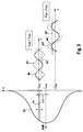
- Fig.2 shows schematic diagrams with spectra of an external cavity and spectra of an mode-selecting filter positioned within the optical path of the external cavity, once optimally matched and once not optimally matched and
- Fig.3 shows a schematic diagram illustrating a generation of control signals for controlling the filter matching.
- Fig. 1 shows a schematic view of an exemplarily laser apparatus 1 according to the invention.
- the laser apparatus 1 comprises an external cavity 2 in which a laser light is provided by a gain medium 10, e.g. a laser diode, to external cavity 2.
- a beam 3 travels along a path between a first cavity end element 11, forming a first end of gain medium 10 and a second cavity end element 40, both cavity end elements 11 and 40 constituting external cavity 2.
- the end elements both provide a high reflectivity.
- a first collimating lens 20 is provided closely to a second end 12 of gain medium 10 within external cavity 2.
- External cavity 2 further comprises a tunable mode-selecting filter 30 introduced in the path of beam 3 for selecting two or more modes out of a comb of longitudinal modes of beam 3.
- External cavity 2 further comprises an output for emitting an output beam 4 as a portion of beam 3, collimated by a second collimating lens 50 and detected by an optical detector 60.
- a control unit 50 is electrically connected to each optical detector 60 and tunable mode-selecting filter 30.
- a further gain medium can be inserted (together with a corresponding further collimating lens) into the optical path in front of the second end element 40.
- External cavity 2 allows beam 3 resonating at specific wavelengths or lines, i.e. it allows for the forming specific laser modes.
- Tunable mode-selecting filter 30 selects at least two modes out of these allowed or possible modes.
- the gain medium 10 and the mode selecting filter 30 can be chosen such, that the optical path is substantially free of any chromatic dispersion.
- a further optical device with a tunable negative dispersion is inserted in the optical path to compensate for the dispersion of the gain medium and the optical filter.
- Detector 60 receives a portion of output beam 4 and generates an electrical current that is proportional to the optical power of beam 3.
- the optical power of output beam 4 is a function that can be seen as a superposition of a constant function and a plurality of sinusoidal functions. For the example with two modes, this signal comprises five portions:
- detector 60 As detector 60 has low pass characteristics, it substantially only detects the constant part and the mixed part of the power of beam 3 and thus generates detection signal DS as sinusoidal function of the frequency difference f2 -f1 (e.g. 12 GHz according to the above example) with a certain offset.
- the electrical line receiving detection signal DS preferably has band pass characteristics so that the offset is suppressed.
- a sinusoidal signal is generated of only one frequency.
- the frequency of this signal is very stable so that apparatus 1 forms a high quality opto-electrical oscillator.
- control unit 70 is provided for controlling the characteristics of mode-selecting filter 30 to ensure a stabilized lasing at the selected modes. Control unit 70 therefore generates control signal CS, that is based on an evaluation of detection signal DS.
- Mode-selecting filter 30 can be realized as a periodical filter, e.g. as Fabry Perot (FP) etalon, ring resonator, acousto-optical filter, Mach-Zender Interferometer, or a Michelson Interferometer.
- a periodical filter e.g. as Fabry Perot (FP) etalon, ring resonator, acousto-optical filter, Mach-Zender Interferometer, or a Michelson Interferometer.
- FP Fabry Perot
- this filter is mounted pivotable by an actuator (not shown) (indicated by the double arrow in Fig.1) around a pivot axis perpendicular to the optical axis of external cavity 2.
- the actuator rotates the etalon into a determined position.
- the free spectral range of the etalon changes. Further details of adjusting the free spectral range of an FP etalon by changing the angle of incidence are described in US 5,331,651.
- the external cavity 2 is tuned for adjusting first spectral characteristics FSR1 of the cavity to the second spectral characteristics FSR2 of the mode-selecting filter 30 (the spectral characteristics of mode-selecting filter is the free spectral range FSR2 , if a periodical filter is used). Therefore, e.g. second cavity end element 40 is mounted on one end of an electrically driven piezo-electric element (not shown), which provides a movement along the optical axis and thus allows for changing the length of the optical path. One end of the piezo-electric element is movable whereas the other end of the piezo-electric element is fixed relative the cavity 2.
- second cavity end element 40 is moved along the optical axis, either towards or away from first cavity end element 11, so that first free spectra range is changed according to the movement.
- adjusting the first spectral characteristics can be carried out by changing the path length directly (by moving cavity elements) or indirectly (e.g. by controlling the temperature, pressure, electric or magnetic field), by adding optical devices with different refractive indices or by controlling the refractive index of optical devices within the path. Therefore, optical devices of LCD or LiNb03 can be used that change the refractive index depending on the applied electrical field.
- both devices might be tuned. Such an arrangement offers a great flexibility and a wide adjustment range.
- the alignment of the spectral characteristics of external cavity 2 and mode-selecting filter 30 is ensured by controlling the environmental conditions of the setup so that an optimal tuning of apparatus 1, once established before operation, e.g. during construction or in maintenance phases, is maintained during operation.
- the external cavity further comprises active mode locking means or passive mode locking means (not shown in Fig.1).
- Active mode locking means e.g. comprise a tunable attenuator or gain modulated according to an attenuator control signal that might be generated additionally by control unit 70 or by a separate control unit.
- Mode locking means are used to prevent from mode competition and thus stabilize the modes chosen.
- an external cavity might be realized as a ring, wherein beam 3 circulates along an optical path formed e.g. by three or more mirrors or a curved waveguide (e.g. a fiber).
- an arrangement of two or more filters e.g. two filters positioned in series, is used.
- the resulting transmission spectrum of an arrangement with filters positioned in series is the multiplication result of the transmission spectra of these filters.
- Fig.2 is a graphical representation of the filter spectra of external cavity 2, of mode-selecting filter 30 and of the resulting light intensity of laser beam 3 (and thus also of beam 4) as a function of the wavelength ⁇ (abscissa).
- the light intensity is denoted in intensity attenuation in a logarithmic scale A/dB (ordinate).
- a first diagram I in the upper part shows an optimal matching of a first spectrum S1 of external cavity 2 shown in Fig.1 and a second spectrum S2 of mode-selecting filter 30 shown in Fig.1 with two resulting laser modes M1 and M2 with substantially similar power.
- a second diagram in the lower part a sub-optimal matching of those devices with two modified modes M1' and M2' having substantially different power. It is understood that the shapes the spectra S1 and S2 in Fig.2 (and in Fig.3 too) are no measurement results of real devices and serve only for describing the invention.
- the cavity spectral characteristics are kept fix, whereas the filter function of mode-selecting filter, (or generally the transmission spectrum S2 of mode-selecting filter arrangement comprising one or a plurality optical filters) is tuned or matched to the accordingly fixed transmission spectrum S1.
- First diagram I shows first spectrum S1 of external cavity 2 with a number first peaks at frequency f 1 , f 2 , f 3 , f 4 ,..., f m , f m+1 , substantially equally spaced with a first frequency distance or first free spectral range FSR1 between two adjacent peaks and a spectrum S2 with second peaks at first and frequencies f 1 and f m , with a second frequency distance or second free spectral range FSR2.
- the second peaks are relatively narrow compared to the first peaks, i.e. the finesse of mode-selecting filter is greater than the finesse of external cavity 2.
- Second free spectral range FSR2 is an exact multiple of first spectral free range FSR1 and thus peaks of both spectra S1 and S2 are centered around frequencies f 1 and f m ; thus both external cavity 2 and mode-selecting filter 30 are tuned so that the filter characteristics are optimally matched.
- Second diagram II distinguishes from first diagram 1 in that the free spectral range of mode-selecting filter 30, further referred to as misaligned free spectral range FSR2', is not an exact multiple of first free spectral range FSR1 and thus peaks of first spectrum S1 and consequently modified spectrum S2 are not centered around m-th frequency f m (there might be also a slight shift of the peaks at first frequency f 1 ); thus the filter characteristics of both external cavity 2 and mode-selecting filter 30 are mismatched resulting in a significant reduction of the power of the second selected mode S2'. It is however important to mention that the problem of misalignment is mainly due the potential change of power over the time; it is not necessary that the power of the selected modes is equal or substantially equal, as long as all selected modes have sufficient power.
- the second peaks are relatively narrow compared to the first peaks, i.e. the finesse of mode-selecting filter 30 is greater than the finesse of external cavity 2.
- the FSR of a periodic optical device (filter or cavity) is defined as being the distance (in frequency space) between adjacent transmission peaks.
- Fig.3 shows at the left side a selected mode out of the laser modes and a part of mode-selecting filter 30 and each with a first peak P1 being the selected mode and a second peak P2 being a part of second spectrum S2 as a function of the wavelength ⁇ (abscissa).
- the external cavity characteristics are tuned, e.g. by varying the external cavity length (It is also possible to tune the filter characteristics by varying mode-selecting filter 30).
- Second peak P2 is centered on a first center wavelength ⁇ C1 and first peak P1 is modulated around second center wavelength ⁇ C2 , said modulation indicated by a double arrow.
- the average wavelength shift or displacement ⁇ ⁇ C2 - ⁇ C1 is positive.
- filter attenuation A/dB is again denoted at a logarithmic scale.
- Fig.3 further shows for a first example with displacement ⁇ > 0 and for a second example with displacement ⁇ ⁇ 0, each an exemplary first or second detection signal D1 or D1', a first or second modulation signal M1 or M1' and a first or second result signal R1 or R1' respectively, said first or second result signal R1 or R1' resulting from averaging the result of a multiplication of the corresponding detection signal and modulation signal.
- First (filter) modulation signal M1 is a sinusoidal part of control signal CS, said control signal having additionally a modulation offset.
- Control signal CS is provided to the actuator of mode-selecting filter 30 for tuning the external cavity characteristics (here: free spectral range) FSR1 and thus for tuning the second center wavelength ⁇ C2 .
- control signal CS is composed of an offset signal (that has a value such that external cavity 2 exhibits a wavelength displacement of ⁇ ) and a periodical function (that e.g. is a sinusoidal function of a frequency of e.g.
- first detection signal D1 has a phase shift of 180 degree compared to first modulation signal M1. Multiplying said signals and determining the average results in a negative result function R1, (that only has a constant value in ideal case).
- the modulation offset is now determined as function of first result function R1, e.g. being negative proportional to first result function ( ⁇ -R1)
- Example with displacement ⁇ ⁇ 0 This example distinguishes over the first example in that the phase of second detection signal D2 has no phase shift compared to second modulation signal M2. Multiplying said signals and determining the average results in positive result function R2, and thus in a negative modulation offset.
- External cavity 2 can be modulated up to a wavelength displacement ⁇ of at least a fraction of the first free spectral range FSR1.
- the maximum allowable wavelength displacement ⁇ in an application as described above is dependant on the filter width (FWHM) and the finesse (F) of the applied filters.
- the modulated transmission signal is thus used to open loop or closed a loop control of the displacement ⁇ between selected peaks of external cavity 2 and mode-selecting filter 30.
Abstract
Description
- The present invention relates to external cavity lasers.
- An external cavity laser comprises a cavity that provides an optical path so that a laser beam, stimulated by a gain or active medium, can resonate. The optical spectrum of an external cavity laser is limited by the spectral region over which the gain medium yields optical gain. Depending on the geometry of the cavity, the laser radiation has certain allowed spectral modes, also referred to as longitudinal modes. The spectral modes correspond to different distinct wavelengths or frequencies of the light. The allowed radiation spectrum in a laser cavity thus is a discrete distribution of modal frequencies limited by the gain curve. Examples of external cavity lasers can be found in US-A- 5,331,651, EP-A-0 552 394 and in EP-A-1 202 409.
- US 5,331,651 discloses a tuneable Fabry Perot etalon to be used in an external cavity laser comprising a semiconductor laser chip and adjustable diffraction grating. The adjustable diffraction grating is used for a coarse measurement of the laser output wavelength and the etalon is used for the fine adjustment.
- It is an object of the invention to provide a laser apparatus with an external cavity for a stable resonation at multiple selected modes. The object is solved by the independent claims. Preferred embodiments are shown by the dependent claims.
- According to the present invention, a laser apparatus comprising an external cavity that provides an optical path for generating a laser beam stimulated by a gain medium, the external cavity having a first spectral characteristic, and further comprises a mode-selecting filter mounted within the optical path, having a second spectral characteristic. The spectral response of such an arrangement corresponds to a multiplication of the spectra of the cavity and the mode-selecting filter(s). Thus, all that modes are selected that fall within the pass bands of the resulting spectrum. In order to achieve a matching of the mode-selecting filter and the external cavity, the first characteristic and the second characteristic are adjusted to each other, e.g. by design, by open loop control or by closed loop control, so that the laser beam comprises at least two selected modes.
- Preferably, the selected modes substantially comprise all the same optical power.
- In an embodiment the laser apparatus comprises an adjustment device to tune (for re-adjusting or changing) the first characteristics and the second characteristics.
- In a further embodiment, the laser apparatus comprises measurement means for determining a physical property related to the laser apparatus, e.g. the optical power of the laser beam and a feed back loop to the adjustment device. On the base of the measured physical property, a control signal is generated to control the adjustment device such, that a matching of the external cavity and the mode-selecting filter is kept.
- In order to achieve a lasing on at least two modes with a narrow bandwidth or high finesse periodical filter, constant gain is required at the corresponding pass bands. The invention has the advantage that variations of laser apparatus characteristics over the time, e.g. due to environmental conditions or to aging, leading to a mismatch of the spectral characteristics and thus resulting in a reduced modal power and instabilities of optical power can be avoided.
- In a further embodiment, the adjustment means are adapted to adjust the first characteristics and the second characteristics by changing the geometry of the external cavity, e.g. the cavity length or the refractive index within the optical path and/or the geometry of the mode-selecting filter. It is also possible to adjust the characteristics by changing the refractive index of the material conducting the laser beam.
- In a further embodiment, the mode-selecting filter consists of at least one periodical filter, so that the first characteristics and the second characteristics can be expressed as a first spectral range (FSR1) of the external cavity and a second free spectral range (FSR2) of the mode-selecting filter respectively. The adjustment means are adapted to adjust said characteristics such that the ratio between the first free spectral range (FSR2) and the second free spectral (FSR1) range is substantially a rational number, especially a natural number.
- In a further embodiment, an opto-electrical converter is comprised for receiving a portion of the laser beam, that can be coupled out by means of a high reflectivity mirror at one end of the external cavity that reflects the main portion of the resonating laser beam and transmits a small portion (e.g. 5%) to the opto-electrical converter. The opto-electrical converter generates an electrical detection signal that is proportional to the actual power of the laser beam.
- In further embodiment, band pass filtering means are comprised for generating an electrical output signal out of the electrical detection signal by letting through only down-mixed frequencies, i.e. signal portions at differences of frequencies of different laser modes, and blocking the offset voltage and non down-mixed high frequencies.
- In a further embodiment, a control unit is comprised for receiving the detection signal or a signal derived from the detection signal (e.g. derived by means of filtering) and generating a control signal for tuning (i.e. adjusting the spectral characteristics of) the at least one of the external cavity and the mode-selecting filter.
- In a further embodiment, the control signal controlling the spectral characteristics (FSR1, FSR2) of at least one of the external cavity and the mode-selecting filter is composed of an offset value corresponding to a desired wavelength displacement between selected peaks and a modulation signal for modulating said free spectral range and wherein the offset value is determined on the base of an averaged value of a multiplication of the detection signal and the modulation signal.
- In a further embodiment, environmental conditions such as temperature and/or pressure are controlled so that the initial settings of the spectral characteristics (FSR1, FSR2) are maintained. Thus, the spectral characteristics are indirectly controlled without a need to build up a feed back loop over a detector and a control unit to an actuator of the external cavity or the mode-selecting filter. This method can also be applied additionally to a feedback control of said devices.
- The external cavity preferably comprises one of active mode locking means and passive mode locking means. For an active mode locking, an electrical modulation of an optical element of the external cavity is performed, e.g. by a modulation of gain medium itself or of by a modulation of a controllable attenuator positioned within the optical path of the external cavity, e.g. by means of an electro absorption modulator (EAM) or a Mach Zehnder modulator.
- The mode-selecting filter might comprise or consist of one of a Fabry Perot etalon, an acousto-optical filter, a ring resonator, a Michelson interferometer, and a Mach Zehnder interferometer.
- The invention can be partly or entirely embodied or supported by one or more suitable software programs, which can be stored on or otherwise provided by any kind of data carrier, and which might be executed in or by any suitable data processing unit.
- In an embodiment, a software program or product for controlling the laser apparatus is comprised for executing in the control unit the method of receiving an electrical detection signal coming from the detection unit that is proportional to the power of the laser beam and generating a control signal to be applied to adjustment means of at least one of the external cavity and mode selecting filter, so that the laser beam comprises at least two selected modes.
- Other objects and many of the attendant advantages of embodiments of the present invention will be readily appreciated and become better understood by reference to the following more detailed description of preferred embodiments in connection with the accompanied drawings. Features that are substantially or functionally equal or similar will be referred to with the same reference signs.
- Fig.1 shows a schematic block diagram of an exemplarily laser apparatus according to the invention,
- Fig.2 shows schematic diagrams with spectra of an external cavity and spectra of an mode-selecting filter positioned within the optical path of the external cavity, once optimally matched and once not optimally matched and
- Fig.3 shows a schematic diagram illustrating a generation of control signals for controlling the filter matching.
- Referring now in greater detail to the drawings, Fig. 1 shows a schematic view of an
exemplarily laser apparatus 1 according to the invention. Thelaser apparatus 1 comprises anexternal cavity 2 in which a laser light is provided by again medium 10, e.g. a laser diode, toexternal cavity 2. A beam 3 travels along a path between a firstcavity end element 11, forming a first end ofgain medium 10 and a secondcavity end element 40, bothcavity end elements external cavity 2. The end elements both provide a high reflectivity. A firstcollimating lens 20 is provided closely to asecond end 12 ofgain medium 10 withinexternal cavity 2.External cavity 2 further comprises a tunable mode-selectingfilter 30 introduced in the path of beam 3 for selecting two or more modes out of a comb of longitudinal modes of beam 3.External cavity 2 further comprises an output for emitting an output beam 4 as a portion of beam 3, collimated by a secondcollimating lens 50 and detected by anoptical detector 60. Acontrol unit 50 is electrically connected to eachoptical detector 60 and tunable mode-selectingfilter 30. - Additionally, a further gain medium can be inserted (together with a corresponding further collimating lens) into the optical path in front of the
second end element 40. -
External cavity 2 allows beam 3 resonating at specific wavelengths or lines, i.e. it allows for the forming specific laser modes. Tunable mode-selectingfilter 30 selects at least two modes out of these allowed or possible modes. - In order to achieve a generation of a plurality of modes over a broad wavelength range, it is important to minimize the chromatic dispersion of the optical path. Therefore, the
gain medium 10 and themode selecting filter 30 can be chosen such, that the optical path is substantially free of any chromatic dispersion. Alternatively, a further optical device with a tunable negative dispersion is inserted in the optical path to compensate for the dispersion of the gain medium and the optical filter. - As an example, two modes are selected with frequencies of 190 Tera Hertz (THz) as first mode frequency f1 and at 190 THz + 12 Giga Hertz (GHz) as second mode frequency f2.
Detector 60 receives a portion of output beam 4 and generates an electrical current that is proportional to the optical power of beam 3. The optical power of output beam 4 is a function that can be seen as a superposition of a constant function and a plurality of sinusoidal functions. For the example with two modes, this signal comprises five portions: - a constant function representing the mean optical power of output beam 4,
- a sinusoidal function with a frequency of two times the first mode frequency (2·f1),
- a sinusoidal function with a frequency of two times the second mode frequency(2·f2),
- a sinusoidal function with a frequency of the sum of the first and second mode frequency (f1+ f2), and
- a sinusoidal function with a frequency of the difference of the first and second mode frequency (f2- f1), the so-called mixed signal.
- As
detector 60 has low pass characteristics, it substantially only detects the constant part and the mixed part of the power of beam 3 and thus generates detection signal DS as sinusoidal function of the frequency difference f2 -f1 (e.g. 12 GHz according to the above example) with a certain offset. The electrical line receiving detection signal DS preferably has band pass characteristics so that the offset is suppressed. Thus, as result a sinusoidal signal is generated of only one frequency. The frequency of this signal is very stable so thatapparatus 1 forms a high quality opto-electrical oscillator. - However, without controlling the matching of
external cavity 2 and mode-selectingfilter 30, it might happen that one of the originally selected modes disappears due to a shift of the spectral characteristics ofexternal cavity 2 and/or of mode-selectingfilter 30 due to environmental changes (e.g. the temperature). Therefore,control unit 70 is provided for controlling the characteristics of mode-selectingfilter 30 to ensure a stabilized lasing at the selected modes.Control unit 70 therefore generates control signal CS, that is based on an evaluation of detection signal DS. - Mode-selecting
filter 30 can be realized as a periodical filter, e.g. as Fabry Perot (FP) etalon, ring resonator, acousto-optical filter, Mach-Zender Interferometer, or a Michelson Interferometer. - For the example of using an FP etalon as mode-selecting
filter 30, this filter is mounted pivotable by an actuator (not shown) (indicated by the double arrow in Fig.1) around a pivot axis perpendicular to the optical axis ofexternal cavity 2. Depending on control signal CS, the actuator rotates the etalon into a determined position. By rotating the etalon, the free spectral range of the etalon changes. Further details of adjusting the free spectral range of an FP etalon by changing the angle of incidence are described in US 5,331,651. - Alternatively to tuning the mode-selecting
filter 30, theexternal cavity 2 is tuned for adjusting first spectral characteristics FSR1 of the cavity to the second spectral characteristics FSR2 of the mode-selecting filter 30 (the spectral characteristics of mode-selecting filter is the free spectral range FSR2 , if a periodical filter is used). Therefore, e.g. secondcavity end element 40 is mounted on one end of an electrically driven piezo-electric element (not shown), which provides a movement along the optical axis and thus allows for changing the length of the optical path. One end of the piezo-electric element is movable whereas the other end of the piezo-electric element is fixed relative thecavity 2. Providing a voltage to the piezo-electric element, secondcavity end element 40 is moved along the optical axis, either towards or away from firstcavity end element 11, so that first free spectra range is changed according to the movement. Generally, adjusting the first spectral characteristics can be carried out by changing the path length directly (by moving cavity elements) or indirectly (e.g. by controlling the temperature, pressure, electric or magnetic field), by adding optical devices with different refractive indices or by controlling the refractive index of optical devices within the path. Therefore, optical devices of LCD or LiNb03 can be used that change the refractive index depending on the applied electrical field. - Alternatively to only tuning either
external cavity 2 or mode-selectingfilter 30, both devices might be tuned. Such an arrangement offers a great flexibility and a wide adjustment range. - Further alternatively, the alignment of the spectral characteristics of
external cavity 2 and mode-selectingfilter 30 is ensured by controlling the environmental conditions of the setup so that an optimal tuning ofapparatus 1, once established before operation, e.g. during construction or in maintenance phases, is maintained during operation. - Preferably, the external cavity further comprises active mode locking means or passive mode locking means (not shown in Fig.1). Active mode locking means e.g. comprise a tunable attenuator or gain modulated according to an attenuator control signal that might be generated additionally by
control unit 70 or by a separate control unit. Mode locking means are used to prevent from mode competition and thus stabilize the modes chosen. - Alternatively to
external cavity 2 with two cavity end elements, an external cavity might be realized as a ring, wherein beam 3 circulates along an optical path formed e.g. by three or more mirrors or a curved waveguide (e.g. a fiber). - Instead of using one single mode-selecting
filter 30, an arrangement of two or more filters, e.g. two filters positioned in series, is used. The resulting transmission spectrum of an arrangement with filters positioned in series is the multiplication result of the transmission spectra of these filters. - In the following, the adjustment of
external cavity 2 and mode-selectingfilter 30 to each other is described in more details. - Fig.2 is a graphical representation of the filter spectra of
external cavity 2, of mode-selectingfilter 30 and of the resulting light intensity of laser beam 3 (and thus also of beam 4) as a function of the wavelength λ (abscissa). The light intensity is denoted in intensity attenuation in a logarithmic scale A/dB (ordinate). A first diagram I in the upper part shows an optimal matching of a first spectrum S1 ofexternal cavity 2 shown in Fig.1 and a second spectrum S2 of mode-selectingfilter 30 shown in Fig.1 with two resulting laser modes M1 and M2 with substantially similar power. A second diagram in the lower part a sub-optimal matching of those devices with two modified modes M1' and M2' having substantially different power. It is understood that the shapes the spectra S1 and S2 in Fig.2 (and in Fig.3 too) are no measurement results of real devices and serve only for describing the invention. - According to Fig.1 and by way of example, the cavity spectral characteristics are kept fix, whereas the filter function of mode-selecting filter, (or generally the transmission spectrum S2 of mode-selecting filter arrangement comprising one or a plurality optical filters) is tuned or matched to the accordingly fixed transmission spectrum S1.
- First diagram I shows first spectrum S1 of
external cavity 2 with a number first peaks at frequency f1, f2, f3, f4,..., fm, fm+1, substantially equally spaced with a first frequency distance or first free spectral range FSR1 between two adjacent peaks and a spectrum S2 with second peaks at first and frequencies f1 and fm, with a second frequency distance or second free spectral range FSR2. By way of example the second peaks are relatively narrow compared to the first peaks, i.e. the finesse of mode-selecting filter is greater than the finesse ofexternal cavity 2. Second free spectral range FSR2 is an exact multiple of first spectral free range FSR1 and thus peaks of both spectra S1 and S2 are centered around frequencies f1 and fm; thus bothexternal cavity 2 and mode-selectingfilter 30 are tuned so that the filter characteristics are optimally matched. - Second diagram II distinguishes from first diagram 1 in that the free spectral range of mode-selecting
filter 30, further referred to as misaligned free spectral range FSR2', is not an exact multiple of first free spectral range FSR1 and thus peaks of first spectrum S1 and consequently modified spectrum S2 are not centered around m-th frequency fm (there might be also a slight shift of the peaks at first frequency f1); thus the filter characteristics of bothexternal cavity 2 and mode-selectingfilter 30 are mismatched resulting in a significant reduction of the power of the second selected mode S2'. It is however important to mention that the problem of misalignment is mainly due the potential change of power over the time; it is not necessary that the power of the selected modes is equal or substantially equal, as long as all selected modes have sufficient power. - By way of example the second peaks are relatively narrow compared to the first peaks, i.e. the finesse of mode-selecting
filter 30 is greater than the finesse ofexternal cavity 2. The finesse F being a figure of merit for the transmission bandwidth is defined by the formula:

- In the following, an exemplary principle for controlling the filter matching will be described, wherein a frequency modulation of mode-selecting
filter 30 will result in an amplitude modulation of the generated beam. Therefore, Fig.3 shows at the left side a selected mode out of the laser modes and a part of mode-selectingfilter 30 and each with a first peak P1 being the selected mode and a second peak P2 being a part of second spectrum S2 as a function of the wavelength λ (abscissa). - In the following example, the external cavity characteristics are tuned, e.g. by varying the external cavity length (It is also possible to tune the filter characteristics by varying mode-selecting filter 30). Second peak P2 is centered on a first center wavelength λC1 and first peak P1 is modulated around second center wavelength λC2, said modulation indicated by a double arrow. In this first example, the average wavelength shift or displacement Δλ = λC2 - λC1 is positive. Peaks P1 and P2 might correspond to laser mode M2' and to a peak of spectrum mismatched spectrum S2'centered on frequencies fm - Δf and fm respectively shown in second diagram II of Fig.2 (frequency and wavelength are related by the function: c/f = λ). At the ordinate, filter attenuation A/dB is again denoted at a logarithmic scale.
- Fig.3 further shows for a first example with displacement Δλ > 0 and for a second example with displacement Δλ < 0, each an exemplary first or second detection signal D1 or D1', a first or second modulation signal M1 or M1' and a first or second result signal R1 or R1' respectively, said first or second result signal R1 or R1' resulting from averaging the result of a multiplication of the corresponding detection signal and modulation signal.
- Example with displacement Δλ > 0: First (filter) modulation signal M1 is a sinusoidal part of control signal CS, said control signal having additionally a modulation offset. Control signal CS is provided to the actuator of mode-selecting
filter 30 for tuning the external cavity characteristics (here: free spectral range) FSR1 and thus for tuning the second center wavelength λC2. In order to get a feedback information of the actual alignment or adjustment of both the cavity characteristics FSR1 and the filter characteristics FSR2, control signal CS is composed of an offset signal (that has a value such thatexternal cavity 2 exhibits a wavelength displacement of Δλ) and a periodical function (that e.g. is a sinusoidal function of a frequency of e.g. 1 Kilo Hertz) so that the second center wavelength is modulated around second center wavelength λC2. As the optical power of beam 3 resonating in external cavity decreases with an increasing actual wavelength displacement, the phase of first detection signal D1 has a phase shift of 180 degree compared to first modulation signal M1. Multiplying said signals and determining the average results in a negative result function R1, (that only has a constant value in ideal case). The modulation offset is now determined as function of first result function R1, e.g. being negative proportional to first result function (~-R1) - Example with displacement Δλ < 0: This example distinguishes over the first example in that the phase of second detection signal D2 has no phase shift compared to second modulation signal M2. Multiplying said signals and determining the average results in positive result function R2, and thus in a negative modulation offset.
-
External cavity 2 can be modulated up to a wavelength displacement Δλ of at least a fraction of the first free spectral range FSR1. The maximum allowable wavelength displacement Δλ in an application as described above is dependant on the filter width (FWHM) and the finesse (F) of the applied filters. - It is also possible to control mode-selecting filter to a displacement of zero: Δλ = 0. In this case, averaging the multiplication of the corresponding detection and modulation signals equals to zero.
- The modulated transmission signal is thus used to open loop or closed a loop control of the displacement Δλ between selected peaks of
external cavity 2 and mode-selectingfilter 30. The displacement Δλ can be controlled to Δλ=0 or to Δλ=a, a being a positive or negative wavelength value depending on the spectral characteristics of the used optical devices and the requested signal behavior.
Claims (14)
- A laser apparatus (1) for providing a stabilized multi mode laser beam (3), comprising:an external cavity (2) providing an optical path for generating a laser beam (3) which is stimulated by a gain medium (10), said external cavity (2) having first spectral characteristics (FSR1) anda mode-selecting filter (30) positioned within the optical path and having second spectral characteristics (FSR2),wherein the first characteristics (FSR1) and the second characteristics (FSR2) are adjusted to each other, so that the laser beam (3) comprises at least two selected modes.
- The apparatus of claim 1, further comprising:an adjustment device (30) adapted to readjust the first characteristics (FSR1) and the second characteristics (FSR2) to each other.
- The apparatus of claim 2, further comprising:a measurement unit (60) adapted to determine a physical property related to the laser apparatus (1) and to generate a corresponding control signal (CS), andan adjustment device (30) adapted to adjust the first characteristics (FSR1) and the second characteristics (FSR2) to each other in dependence of said control signal (CS).
- The apparatus of claim 2 or 3, wherein the adjustment device (30) is adapted to adjust the first characteristics (FSR1) and the second characteristics (FSR2) by changing at least one of a geometry and a refractive index of at least one of the external cavity (2) and the mode-selecting filter (30).
- The apparatus of claim 2 or anyone of the above claims, wherein the first characteristics (FSR1) and the second characteristics (FSR2) are each a first spectral range of the external cavity (2) and a second free spectral range of the mode-selecting filter (30) respectively and wherein the adjustment device (30) is adapted to adjust said characteristics such that the ratio between the first free spectral range (FSR2) and the second free spectral (FSR1) range is substantially a rational number, especially a natural number.
- The apparatus of claim 3 or anyone of the above claims, wherein the measurement unit is an opto-electrical converter (60) adapted for receiving a portion (4) of the laser beam (3) and generating an electrical detection signal (DS) that is proportional to the actual power of the laser beam (3).
- The apparatus of claim 6, further comprising band pass filtering means (5) adapted for generating an electrical output signal out of the electrical detection signal (DS) by letting through only down-mixed frequencies and blocking the offset voltage and non down-mixed high frequencies.
- The apparatus of claim 6 or 7, comprising a control unit (70) adapted to receive the detection signal (DS) or a signal derived from the detection signal (DS) and generating a control signal (CS) to be provided to at least one of the external cavity and the mode-selecting filter (30) for adjusting the first characteristics (FSR1) and the second characteristics (FSR2) to each other.
- The apparatus of claim 8, wherein the control unit (70) is adapted for generating a control signal (CS) that is composed of an offset value corresponding to a desired wavelength displacement (Δλ) between selected peaks and a modulation signal (M1, M1') for modulating said free spectral range and wherein the offset value is determined on the base of an averaged value of a multiplication of the detection signal (DS) and the modulation signal (MS, MS').
- The apparatus of claim 8, wherein the control unit (70) is adapted for controlling environmental conditions such that an initial setting of the spectral characteristics (FSR1, FSR2) is maintained.
- The apparatus of claim 1 or any one of the above claims, wherein the external cavity (2) further comprises one of active mode locking means and passive mode locking means.
- The apparatus of claim 1 or any one of the above claims, wherein the mode-selecting filter (30) comprises one of a Fabry Perot etalon, an acousto-optical filter, a ring resonator, a Michelson interferometer, and a Mach Zehnder interferometer.
- A method of controlling a laser apparatus (1), wherein the laser apparatus comprises an external cavity (2) with an optical path for receiving a laser beam (3) that is stimulated by a gain medium (10), said external cavity (2) having first spectral characteristics (FSR1), and a mode-selecting filter (30) positioned within the optical path said mode-selecting filter (30) having second spectral characteristics (FSR2), comprising:measuring a physical property related to the laser apparatus (1),adjusting on the base of said physical property at least one of the external cavity (2) and the mode-selecting filter (30) for adjusting the first characteristics (FSR1) and the second characteristics (FSR2) to each other, so that the laser beam (3) comprises at least two selected modes.
- A software program or product, preferably stored on a data carrier, for controlling a laser apparatus (1), said laser apparatus comprising an external cavity (2) having first spectral characteristics (FSR1), and further comprising a mode-selecting filter (30) positioned within an optical path of the external cavity (2) and having second spectral characteristics (FSR2), for executing the method of:receiving an electrical detection signal (DS) that is based on a physical property (3) of the laser apparatus (1), andgenerating a control signal (CS) to be applied to adjustment means of at least one of the external cavity (2) and mode selecting filter (30) so that a laser beam (3) resonating in the external cavity (2) comprises at least two selected modes,when run on a data processing system of a control unit (70).
Priority Applications (3)
| Application Number | Priority Date | Filing Date | Title |
|---|---|---|---|
| EP04103969A EP1628374A1 (en) | 2004-08-18 | 2004-08-18 | External cavity laser with multiple stabilized modes |
| US11/149,780 US7496119B2 (en) | 2004-08-18 | 2005-06-10 | External cavity laser with multiple stabilized modes |
| JP2005220548A JP2006060206A (en) | 2004-08-18 | 2005-07-29 | External resonator laser with a plurality of stabilized modes |
Applications Claiming Priority (1)
| Application Number | Priority Date | Filing Date | Title |
|---|---|---|---|
| EP04103969A EP1628374A1 (en) | 2004-08-18 | 2004-08-18 | External cavity laser with multiple stabilized modes |
Publications (1)
| Publication Number | Publication Date |
|---|---|
| EP1628374A1 true EP1628374A1 (en) | 2006-02-22 |
Family
ID=34929460
Family Applications (1)
| Application Number | Title | Priority Date | Filing Date |
|---|---|---|---|
| EP04103969A Withdrawn EP1628374A1 (en) | 2004-08-18 | 2004-08-18 | External cavity laser with multiple stabilized modes |
Country Status (3)
| Country | Link |
|---|---|
| US (1) | US7496119B2 (en) |
| EP (1) | EP1628374A1 (en) |
| JP (1) | JP2006060206A (en) |
Cited By (3)
| Publication number | Priority date | Publication date | Assignee | Title |
|---|---|---|---|---|
| WO2007022796A1 (en) | 2005-08-24 | 2007-03-01 | Agilent Technologies, Inc. | Polarization maintaining optical delay circuit |
| CN102780158A (en) * | 2011-05-09 | 2012-11-14 | 中国科学院深圳先进技术研究院 | Tunable external-cavity semiconductor laser |
| US8416831B2 (en) | 2006-12-18 | 2013-04-09 | Toptica Photonics Ag | Laser light source |
Families Citing this family (11)
| Publication number | Priority date | Publication date | Assignee | Title |
|---|---|---|---|---|
| JPWO2007004509A1 (en) * | 2005-07-01 | 2009-01-29 | 日本電気株式会社 | External cavity type wavelength tunable laser device and optical output module |
| JP2008066705A (en) | 2006-08-11 | 2008-03-21 | Seiko Epson Corp | Laser light source device and projector comprising the same |
| WO2009060365A1 (en) * | 2007-11-07 | 2009-05-14 | Koninklijke Philips Electronics N.V. | Extended cavity semiconductor laser device with increased intensity |
| US8625650B2 (en) | 2009-04-03 | 2014-01-07 | Exalos Ag | Light source, and optical coherence tomography module |
| JP2011222766A (en) * | 2010-04-09 | 2011-11-04 | Mitsubishi Electric Corp | Measuring device for semiconductor laser diode |
| JP6104924B2 (en) * | 2011-10-28 | 2017-03-29 | オーエフエス ファイテル,エルエルシー | Distributed feedback (DFB) Brillouin fiber laser |
| EP2933886B1 (en) * | 2014-04-16 | 2019-08-28 | DirectPhotonics Industries GmbH | Laser beam generating device and method for adjusting a wavelength of a laser beam |
| US10109983B2 (en) | 2016-04-28 | 2018-10-23 | Hewlett Packard Enterprise Development Lp | Devices with quantum dots |
| US10566765B2 (en) | 2016-10-27 | 2020-02-18 | Hewlett Packard Enterprise Development Lp | Multi-wavelength semiconductor lasers |
| US10680407B2 (en) * | 2017-04-10 | 2020-06-09 | Hewlett Packard Enterprise Development Lp | Multi-wavelength semiconductor comb lasers |
| US10396521B2 (en) | 2017-09-29 | 2019-08-27 | Hewlett Packard Enterprise Development Lp | Laser |
Citations (4)
| Publication number | Priority date | Publication date | Assignee | Title |
|---|---|---|---|---|
| EP0762573A1 (en) * | 1995-08-25 | 1997-03-12 | Anritsu Corporation | Tunable wavelength laser light source apparatus using compound cavity such as compound cavity semiconductor laser |
| WO2002075874A1 (en) * | 2001-03-16 | 2002-09-26 | Intel Corporation (A Corporation Of Delaware) | Method and apparatus for tuning a laser |
| US20020172239A1 (en) * | 1999-07-27 | 2002-11-21 | Mcdonald Mark E. | Tunable external cavity laser |
| US20030007522A1 (en) * | 2001-07-06 | 2003-01-09 | Hua Li | External cavity laser with orthogonal tuning of laser wavelength and cavity optical path length |
Family Cites Families (9)
| Publication number | Priority date | Publication date | Assignee | Title |
|---|---|---|---|---|
| DE69200586T2 (en) | 1992-01-24 | 1995-05-24 | Hewlett Packard Gmbh | Method and apparatus for tuning the wavelength in an optical device and its use in a laser. |
| US5392308A (en) * | 1993-01-07 | 1995-02-21 | Sdl, Inc. | Semiconductor laser with integral spatial mode filter |
| US7120176B2 (en) * | 2000-07-27 | 2006-10-10 | Intel Corporation | Wavelength reference apparatus and method |
| EP1202409B1 (en) | 2001-06-01 | 2003-04-16 | Agilent Technologies, Inc. (a Delaware corporation) | Tuning a laser |
| US6631146B2 (en) * | 2001-07-06 | 2003-10-07 | Intel Corporation | Tunable laser control system |
| US6816517B2 (en) * | 2001-09-25 | 2004-11-09 | International Business Machines Corporation | Micro-electromechanical devices for wavelength tunable lasers |
| US6658032B2 (en) * | 2001-10-05 | 2003-12-02 | Pranalytica, Inc. | Automated laser wavelength selection system and method |
| US6947218B2 (en) * | 2002-08-30 | 2005-09-20 | Research Electro-Optics, Inc. | Fabry-perot etalon with independently selectable resonance frequency and free spectral range |
| US7061946B2 (en) * | 2002-11-13 | 2006-06-13 | Intel Corporation | Intra-cavity etalon with asymmetric power transfer function |
-
2004
- 2004-08-18 EP EP04103969A patent/EP1628374A1/en not_active Withdrawn
-
2005
- 2005-06-10 US US11/149,780 patent/US7496119B2/en not_active Expired - Fee Related
- 2005-07-29 JP JP2005220548A patent/JP2006060206A/en active Pending
Patent Citations (4)
| Publication number | Priority date | Publication date | Assignee | Title |
|---|---|---|---|---|
| EP0762573A1 (en) * | 1995-08-25 | 1997-03-12 | Anritsu Corporation | Tunable wavelength laser light source apparatus using compound cavity such as compound cavity semiconductor laser |
| US20020172239A1 (en) * | 1999-07-27 | 2002-11-21 | Mcdonald Mark E. | Tunable external cavity laser |
| WO2002075874A1 (en) * | 2001-03-16 | 2002-09-26 | Intel Corporation (A Corporation Of Delaware) | Method and apparatus for tuning a laser |
| US20030007522A1 (en) * | 2001-07-06 | 2003-01-09 | Hua Li | External cavity laser with orthogonal tuning of laser wavelength and cavity optical path length |
Cited By (4)
| Publication number | Priority date | Publication date | Assignee | Title |
|---|---|---|---|---|
| WO2007022796A1 (en) | 2005-08-24 | 2007-03-01 | Agilent Technologies, Inc. | Polarization maintaining optical delay circuit |
| US8416831B2 (en) | 2006-12-18 | 2013-04-09 | Toptica Photonics Ag | Laser light source |
| CN102780158A (en) * | 2011-05-09 | 2012-11-14 | 中国科学院深圳先进技术研究院 | Tunable external-cavity semiconductor laser |
| CN102780158B (en) * | 2011-05-09 | 2014-08-06 | 中国科学院深圳先进技术研究院 | Tunable external-cavity semiconductor laser |
Also Published As
| Publication number | Publication date |
|---|---|
| US20060039424A1 (en) | 2006-02-23 |
| JP2006060206A (en) | 2006-03-02 |
| US7496119B2 (en) | 2009-02-24 |
Similar Documents
| Publication | Publication Date | Title |
|---|---|---|
| US7496119B2 (en) | External cavity laser with multiple stabilized modes | |
| US7505490B2 (en) | Phase-control in an external-cavity tuneable laser | |
| US7257142B2 (en) | Semi-integrated designs for external cavity tunable lasers | |
| US6665321B1 (en) | Tunable laser operation with locally commensurate condition | |
| US6188705B1 (en) | Fiber grating coupled light source capable of tunable, single frequency operation | |
| US8619824B2 (en) | Low white frequency noise tunable semiconductor laser source | |
| EP0641052B1 (en) | Tunable wavelength light source incorporating an interferometer as an optical filter in the external cavity | |
| US6959024B2 (en) | Laser Tuning by spectrally dependent spatial filtering | |
| US20090122817A1 (en) | Variable-wavelength filter and variable-wavelength laser | |
| JP2007505496A (en) | Search and tracking control to lock to transmission peak for tunable lasers | |
| US20030035446A1 (en) | Frequency selective tunable mirror and applications thereof | |
| US20050111498A1 (en) | Mode behavior of single-mode semiconductor lasers | |
| US7356055B2 (en) | Method and device for regulating the average wavelength of a laser, especially a semiconductor laser | |
| JP3976756B2 (en) | Optical frequency comb generator controller | |
| US20230187903A1 (en) | Tunable Laser Diode | |
| US20210344167A1 (en) | System and method for optical feedback stabilized semiconductor frequency combs | |
| KR20060067971A (en) | Phase-control in an external-cavity tuneable laser | |
| WO2003075078A2 (en) | Laser tuning by spectrally dependent spatial filtering |
Legal Events
| Date | Code | Title | Description |
|---|---|---|---|
| PUAI | Public reference made under article 153(3) epc to a published international application that has entered the european phase |
Free format text: ORIGINAL CODE: 0009012 |
|
| AK | Designated contracting states |
Kind code of ref document: A1 Designated state(s): AT BE BG CH CY CZ DE DK EE ES FI FR GB GR HU IE IT LI LU MC NL PL PT RO SE SI SK TR |
|
| AX | Request for extension of the european patent |
Extension state: AL HR LT LV MK |
|
| 17P | Request for examination filed |
Effective date: 20060822 |
|
| AKX | Designation fees paid |
Designated state(s): DE FR GB |
|
| RAP1 | Party data changed (applicant data changed or rights of an application transferred) |
Owner name: AGILENT TECHNOLOGIES, INC. |
|
| 17Q | First examination report despatched |
Effective date: 20071010 |
|
| STAA | Information on the status of an ep patent application or granted ep patent |
Free format text: STATUS: THE APPLICATION IS DEEMED TO BE WITHDRAWN |
|
| 18D | Application deemed to be withdrawn |
Effective date: 20090918 |