EP1201979A2 - Vorrichtung zum Abführen und Einleiten von Inertgas - Google Patents
Vorrichtung zum Abführen und Einleiten von Inertgas Download PDFInfo
- Publication number
- EP1201979A2 EP1201979A2 EP01105647A EP01105647A EP1201979A2 EP 1201979 A2 EP1201979 A2 EP 1201979A2 EP 01105647 A EP01105647 A EP 01105647A EP 01105647 A EP01105647 A EP 01105647A EP 1201979 A2 EP1201979 A2 EP 1201979A2
- Authority
- EP
- European Patent Office
- Prior art keywords
- port
- inert gas
- line
- evacuation
- gas introduction
- Prior art date
- Legal status (The legal status is an assumption and is not a legal conclusion. Google has not performed a legal analysis and makes no representation as to the accuracy of the status listed.)
- Granted
Links
Images

Classifications
-
- F—MECHANICAL ENGINEERING; LIGHTING; HEATING; WEAPONS; BLASTING
- F16—ENGINEERING ELEMENTS AND UNITS; GENERAL MEASURES FOR PRODUCING AND MAINTAINING EFFECTIVE FUNCTIONING OF MACHINES OR INSTALLATIONS; THERMAL INSULATION IN GENERAL
- F16K—VALVES; TAPS; COCKS; ACTUATING-FLOATS; DEVICES FOR VENTING OR AERATING
- F16K11/00—Multiple-way valves, e.g. mixing valves; Pipe fittings incorporating such valves
- F16K11/02—Multiple-way valves, e.g. mixing valves; Pipe fittings incorporating such valves with all movable sealing faces moving as one unit
- F16K11/08—Multiple-way valves, e.g. mixing valves; Pipe fittings incorporating such valves with all movable sealing faces moving as one unit comprising only taps or cocks
- F16K11/083—Multiple-way valves, e.g. mixing valves; Pipe fittings incorporating such valves with all movable sealing faces moving as one unit comprising only taps or cocks with tapered plug
-
- Y—GENERAL TAGGING OF NEW TECHNOLOGICAL DEVELOPMENTS; GENERAL TAGGING OF CROSS-SECTIONAL TECHNOLOGIES SPANNING OVER SEVERAL SECTIONS OF THE IPC; TECHNICAL SUBJECTS COVERED BY FORMER USPC CROSS-REFERENCE ART COLLECTIONS [XRACs] AND DIGESTS
- Y10—TECHNICAL SUBJECTS COVERED BY FORMER USPC
- Y10T—TECHNICAL SUBJECTS COVERED BY FORMER US CLASSIFICATION
- Y10T137/00—Fluid handling
- Y10T137/4238—With cleaner, lubrication added to fluid or liquid sealing at valve interface
- Y10T137/4245—Cleaning or steam sterilizing
- Y10T137/4259—With separate material addition
-
- Y—GENERAL TAGGING OF NEW TECHNOLOGICAL DEVELOPMENTS; GENERAL TAGGING OF CROSS-SECTIONAL TECHNOLOGIES SPANNING OVER SEVERAL SECTIONS OF THE IPC; TECHNICAL SUBJECTS COVERED BY FORMER USPC CROSS-REFERENCE ART COLLECTIONS [XRACs] AND DIGESTS
- Y10—TECHNICAL SUBJECTS COVERED BY FORMER USPC
- Y10T—TECHNICAL SUBJECTS COVERED BY FORMER US CLASSIFICATION
- Y10T137/00—Fluid handling
- Y10T137/8593—Systems
- Y10T137/85978—With pump
- Y10T137/86083—Vacuum pump
-
- Y—GENERAL TAGGING OF NEW TECHNOLOGICAL DEVELOPMENTS; GENERAL TAGGING OF CROSS-SECTIONAL TECHNOLOGIES SPANNING OVER SEVERAL SECTIONS OF THE IPC; TECHNICAL SUBJECTS COVERED BY FORMER USPC CROSS-REFERENCE ART COLLECTIONS [XRACs] AND DIGESTS
- Y10—TECHNICAL SUBJECTS COVERED BY FORMER USPC
- Y10T—TECHNICAL SUBJECTS COVERED BY FORMER US CLASSIFICATION
- Y10T137/00—Fluid handling
- Y10T137/8593—Systems
- Y10T137/86493—Multi-way valve unit
- Y10T137/86574—Supply and exhaust
- Y10T137/86638—Rotary valve
- Y10T137/86646—Plug type
-
- Y—GENERAL TAGGING OF NEW TECHNOLOGICAL DEVELOPMENTS; GENERAL TAGGING OF CROSS-SECTIONAL TECHNOLOGIES SPANNING OVER SEVERAL SECTIONS OF THE IPC; TECHNICAL SUBJECTS COVERED BY FORMER USPC CROSS-REFERENCE ART COLLECTIONS [XRACs] AND DIGESTS
- Y10—TECHNICAL SUBJECTS COVERED BY FORMER USPC
- Y10T—TECHNICAL SUBJECTS COVERED BY FORMER US CLASSIFICATION
- Y10T137/00—Fluid handling
- Y10T137/8593—Systems
- Y10T137/86493—Multi-way valve unit
- Y10T137/86863—Rotary valve unit
- Y10T137/86871—Plug
Definitions
- the present invention relates to a structure of an evacuation and inert gas introduction apparatus.
- the apparatus is suitable for a case where the air contamination in the reaction chamber must be suppressed to an extremely low level, such as in the case of a molecular asymmetric catalyst synthesizing device.
- Molecular asymmetric catalysts have high activities, and therefore they are focused worldwide as one of the core techniques in material conversion.
- the molecular asymmetric catalysts are key materials for creating functional organic materials having new values.
- excellent molecular asymmetric catalysts are developed one after another.
- the number of molecular asymmetric catalytic reactions which have been made practical in industries is small at this point as compared to that of the microbial enzymatic techniques, which are of a traditional industry of Japan, it is expected that the number of such reactions will be increased with accelerating speed. It is highly possible that the molecular asymmetric catalysts are used widely, not only in the medical and agricultural chemicals production industries, but also in the filed of the materials science industry.
- the present invention has been proposed in consideration of the above-described problems regarding the conventional structure of the evacuation line and inert gas introduction line in a molecular asymmetric catalyst synthesizing apparatus.
- an evacuation and insert gas introduction apparatus comprising:
- the line for evacuating the reaction chamber (evacuation line) and the line for introducing an inert gas to the reaction chamber (inert gas introduction line) are made up by different systems from each other, and these lines and the reaction chamber are connected via a three-way cock having the above-described structure. As the three-way cock is rotated, the switching between the evacuation state within the reaction chamber and the inert gas introduction state of the reaction chamber can be carried out quickly by one operation. In this manner, the leakage of the air into the reaction chamber, which may occur during the line switching operation, can be prevented.
- the three-way cock is equipped with a vacuum cavity decompressed to a vacuum, which is provided at a tip end thereof, and therefore there is no such a possible danger that the inside plug of the cock is pushed out when the interior of the reaction chamber is pressurized. Further, the pressure on a ground surface of the cock is maintained high, and therefore it is possible to surely prevent leakage from the ground surface when the interior reaction chamber is evacuated.
- the evacuation and inert gas introduction apparatus of the present invention has an excellent safety in term of operation.
- a preferable embodiment of the apparatus of the present invention has a structure in which:
- Another preferable embodiment of the apparatus of the present invention has a structure in which:
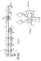
- FIGS. 1 and 2 each show the structure of an evacuation and inert gas introduction apparatus according to the present invention.
- FIGS. 1 and 2 are respectively top and front views.
- a line arranged on an upper side is an evacuation line 10
- a line arranged on a lower side is an inert gas introduction line 20.
- the evacuation line 10 is hidden behind the inert gas introduction line 20, and only the right end portion can be seen in the figure.
- One end (on the right-hand side in the figure) of the evacuation line 10 is connected to one of the ports of the vacuum cock 13, that is, port 13a, via a flange 11 (a remodeled type SKK 40, which is obtained by making an O-ring groove in a glass flange surface, and an O-ring made of Viton (tradename of ### Co.) is provided in the groove to secure the air tightness).
- the tip end portion of the other port, that is, port 13b, of the vacuum cock 13 is inserted to the solvent trap 15.
- the solvent trap 15 is connected to a pipe 17 via the flange 16 (KN50), and a vacuum pump (not shown) is connected to an end of the pipe 17.
- a molecular asymmetric catalyst for example, a single rotary or a combination of a rotary pump and oil diffusion pump, capable of reducing the pressure to 10 -4 to 10 -7 mmHg (1.33 ⁇ 10 -2 to 1.33 ⁇ 10 -5 Pa) is used as a vacuum pump.
- the solvent trap 15 is immersed in a coolant tub (not shown) where liquid nitrogen is stored. While evacuating the reaction chambers (not shown) of the synthesizing device, the solvent trap 15 serves to condensate solvents in the gas to be exhausted (such as halogen-based solvent, hydrocarbon-based solvent, ether-based solvent, water and alcohol), in order to prevent them from entering the vacuum pump (not shown) through the tube 17.
- a branch tube 18a is branched off from the middle of the pipe 17, and a Young's cock 18 is connected to the end of the branched tube 18a. The Young's cock 18 is used to recover the atmospheric pressure within the solvent trap 15 after the completion of the synthesizing operation.
- the other end (on the left-hand side in the figure) of the evacuation line 10 is closed.
- a branched tube 12a is branched off from a vicinity of the other end of the evacuation line 10.
- the Young's cock 12 is connected to the inert gas introduction line 20, and it is usually closed.
- the Young's cock 12 is used to reduce the pressure within the inert gas introduction line 20 in accordance with necessity.
- One end (on the left-hand side end in the figure) of the inert gas introduction line 20 is connected to an inert gas supply source (not shown, but an argon gas cylinder) via a Young's cock 21.
- a branched tube 22a is branched off from a vicinity of the other end of the inert gas introduction line 20.
- a Pirani gauge 23 is connected via a flange 22 (a remodeled type SKK 30, which is obtained by making an O-ring groove in a glass flange surface, and an O-ring name of Viton (tradename of ### Co.) is provided in the groove to secure the air tightness).
- the Pirani gauge 23 is used to measure the vacuum degree of the system as a whole, and the Young's cock 12 is opened for a measurement.
- the evacuation line 10 and the inert gas introduction line 20 are connected to each of the reaction chambers (not shown) of the synthesizing device via four of three-way cocks 30a to 30d arranged in series.
- FIG. 3 is a cross sectional view showing a three-way cock 30 (common to three-way cocks 30a to 30d).
- the three-way cock 30 consists of a housing 35 and an inside plug 37 fitted inside the housing 35.
- the housing 35 has a shape of a circular truncated cone, and a ground surface is formed in its inner surface.
- the first port 31, second port 32 and third port 33 are provided on a lateral surface of the housing 35.
- the first port 31 and the second port 32 are formed on one side of the lateral surface of the housing 35 (on an upper side in FIG. 3), to be arranged in line in the direction of the rotational axis of the inside plug 37, and the third port 33 is formed on the opposite side of the lateral surface (on a lower side in FIG. 3).
- the outer surface of the inside plug 37 is formed to serve as a ground surface, and it is fitted inside the housing 35 via the ground surface.
- the inside plug 37 has two through holes 38a and 38b formed therein such as to cross with the rotation axis diagonally. As the inside plug is rotated by an angle of 180 degrees, a state where the first port 31 is connected to the third port via the through hole 38a and a state where the second port is connected to the third port via the other of the through hole are switched over therebetween by one operation step.
- the tip end portion of the housing 35 is provided with a substantially spherical cavity (vacuum cavity) 36, and the pressure of the inside of the vacuum cavity 36 is reduced.
- the inside plug 37 is attracted towards the vacuum cavity 36, and therefore it is possible to prevent such a trouble that the inside plug 37 is pushed out of the housing 35 when the interior of the reaction chamber is pressurized.
- a pressure is applied to the ground surface of the cock, and thus a high air tightness can be maintained.
- the evacuation line 10 is connected to the first port 31 of the three-way cock 30, the inert gas introduction line 20 is connected to the second port 32 of the three-way cock 30 and the reaction chamber (not shown) of the synthesizing device is connected to the third port 33 of the three-way cock 30.
- the state where the reaction chamber (not shown) of the synthesizing device is connected to the evacuation line 10 is switched to the state where the reaction chamber is connected to the inert gas introduction line (or vice versa in opposite direction) instantaneously by one step operation. In this manner, it is possible to prevent the atmospheric air from leaking into the reaction chamber during the line switching operation after the evacuation.
- the evacuation line 10 and inert gas introduction line 20 are connected to the first flask (not shown) of the synthesizing device via the three-way cock 30a and rubber stopper 41, to the second flask (not shown) via the three-way cock 30b and rubber stopper 42, to the third flask (not shown) via the three-way cock 30c and ground surface joint 43, and to the fourth flask (not shown) via the three-way cock 30d and ball joint 44 (not shown).
- the evacuation and inert gas introduction apparatus of the present invention With the evacuation and inert gas introduction apparatus of the present invention, the air contamination of the interior of the reaction chamber can be significantly reduced, and therefore it becomes possible to synthesize a molecular asymmetrical catalyst having a high purity at high efficiency. It should be noted here that the evacuation and inert gas introduction apparatus of the present invention is useful for synthesizing, other than the molecular asymmetrical catalyst, various types of metal complexes which are extremely unstable against the contamination of air or water.
Landscapes
- Engineering & Computer Science (AREA)
- General Engineering & Computer Science (AREA)
- Mechanical Engineering (AREA)
- Multiple-Way Valves (AREA)
- Physical Or Chemical Processes And Apparatus (AREA)
- Taps Or Cocks (AREA)
- Compressors, Vaccum Pumps And Other Relevant Systems (AREA)
- Catalysts (AREA)
- Organic Low-Molecular-Weight Compounds And Preparation Thereof (AREA)
- Sampling And Sample Adjustment (AREA)
- Devices And Processes Conducted In The Presence Of Fluids And Solid Particles (AREA)
Applications Claiming Priority (2)
| Application Number | Priority Date | Filing Date | Title |
|---|---|---|---|
| JP2000326877A JP3448644B2 (ja) | 2000-10-26 | 2000-10-26 | 真空排気兼不活性ガス導入装置 |
| JP2000326877 | 2000-10-26 |
Publications (3)
| Publication Number | Publication Date |
|---|---|
| EP1201979A2 true EP1201979A2 (de) | 2002-05-02 |
| EP1201979A3 EP1201979A3 (de) | 2003-09-17 |
| EP1201979B1 EP1201979B1 (de) | 2005-03-02 |
Family
ID=18803995
Family Applications (1)
| Application Number | Title | Priority Date | Filing Date |
|---|---|---|---|
| EP01105647A Expired - Lifetime EP1201979B1 (de) | 2000-10-26 | 2001-03-07 | Vorrichtung zum Abführen und Einleiten von Inertgas |
Country Status (5)
| Country | Link |
|---|---|
| US (1) | US6520203B2 (de) |
| EP (1) | EP1201979B1 (de) |
| JP (1) | JP3448644B2 (de) |
| CA (1) | CA2339606C (de) |
| DE (1) | DE60109109T2 (de) |
Families Citing this family (2)
| Publication number | Priority date | Publication date | Assignee | Title |
|---|---|---|---|---|
| US9416919B2 (en) * | 2013-10-11 | 2016-08-16 | Applied Materials, Inc. | Compact hazardous gas line distribution enabling system single point connections for multiple chambers |
| CN108499571A (zh) * | 2018-05-31 | 2018-09-07 | 钦州学院 | 负载型分子筛催化剂用的集成式制备装置 |
Family Cites Families (7)
| Publication number | Priority date | Publication date | Assignee | Title |
|---|---|---|---|---|
| US1830594A (en) * | 1929-12-20 | 1931-11-03 | Air Reduction | Flame regulating cock |
| US3738197A (en) * | 1971-03-17 | 1973-06-12 | Gen Motors Corp | Transmission modulator valve control |
| US4383547A (en) * | 1981-03-27 | 1983-05-17 | Valin Corporation | Purging apparatus |
| US5858065A (en) * | 1995-07-17 | 1999-01-12 | American Air Liquide | Process and system for separation and recovery of perfluorocompound gases |
| DE19547124C2 (de) * | 1995-12-16 | 2001-04-19 | Lpkf D O O | Drehschieberventil zur wahlweisen Druck- oder Saugluftbeaufschlagung |
| JP3737869B2 (ja) * | 1997-05-13 | 2006-01-25 | シーケーディ株式会社 | プロセスガス供給ユニット |
| JP2000249058A (ja) | 1999-02-26 | 2000-09-12 | Ebara Corp | トラップ装置 |
-
2000
- 2000-10-26 JP JP2000326877A patent/JP3448644B2/ja not_active Expired - Lifetime
-
2001
- 2001-03-07 EP EP01105647A patent/EP1201979B1/de not_active Expired - Lifetime
- 2001-03-07 CA CA002339606A patent/CA2339606C/en not_active Expired - Fee Related
- 2001-03-07 DE DE60109109T patent/DE60109109T2/de not_active Expired - Fee Related
- 2001-03-08 US US09/800,468 patent/US6520203B2/en not_active Expired - Fee Related
Non-Patent Citations (1)
| Title |
|---|
| None |
Also Published As
| Publication number | Publication date |
|---|---|
| CA2339606A1 (en) | 2002-04-26 |
| DE60109109T2 (de) | 2005-12-29 |
| EP1201979B1 (de) | 2005-03-02 |
| JP2002130124A (ja) | 2002-05-09 |
| EP1201979A3 (de) | 2003-09-17 |
| JP3448644B2 (ja) | 2003-09-22 |
| US6520203B2 (en) | 2003-02-18 |
| DE60109109D1 (de) | 2005-04-07 |
| CA2339606C (en) | 2003-12-02 |
| US20020050294A1 (en) | 2002-05-02 |
Similar Documents
| Publication | Publication Date | Title |
|---|---|---|
| CN100342962C (zh) | 更换喷嘴的装置 | |
| US6520203B2 (en) | Evacuation and inert gas introduction apparatus | |
| CA2545600C (en) | Device for operating gas in vacuum or low-pressure environment and for observation of the operation | |
| US7388211B2 (en) | Semi-closed observational environment for electron microscope | |
| JP2000161510A (ja) | 回転弁 | |
| JP2936281B2 (ja) | 装置を過圧から保護する器具 | |
| US4212317A (en) | Vacuum interlock | |
| GB2314347A (en) | Reactive PVD with NEG pump | |
| CA2518521C (en) | Method of operating liquid in the vacuum or low-pressure environment and observing the operation and device for the operation and observation | |
| EP0581249A1 (de) | Ultrahoch-Vakuumapparat | |
| US6082414A (en) | Apparatus and method for replacing an attachment on a vacuum chamber | |
| JP3692320B2 (ja) | 円筒型製品のリーク検査装置およびリーク検査用シール装置 | |
| JPH09134913A (ja) | 熱処理装置及びその方法 | |
| KR20060045576A (ko) | 로드로크 및 건식 진공 펌프 조립체 | |
| CN219956465U (zh) | 工艺量测系统 | |
| CN104681383B (zh) | 用于透射式电子显微镜的相位板 | |
| KR101713983B1 (ko) | 차등 배기 구조를 갖는 플라즈마 발생 장치 | |
| JPH07254635A (ja) | 半導体製造装置 | |
| JPH0330320A (ja) | 気相化学反応生成装置のロードロック機構 | |
| US20080073532A1 (en) | Observational liquid/gas environment combined with specimen chamber of electron microscope | |
| JP2007141633A (ja) | 電子顕微鏡 | |
| JP3981723B2 (ja) | ガス密封装置及びセルの密封構造 | |
| JP4634295B2 (ja) | 電子顕微鏡の真空排気装置 | |
| JP2000205418A (ja) | 磁性流体封止型回転導入機 | |
| KR20250045139A (ko) | 가압 진공 겸용 밸브 |
Legal Events
| Date | Code | Title | Description |
|---|---|---|---|
| PUAI | Public reference made under article 153(3) epc to a published international application that has entered the european phase |
Free format text: ORIGINAL CODE: 0009012 |
|
| 17P | Request for examination filed |
Effective date: 20010307 |
|
| AK | Designated contracting states |
Kind code of ref document: A2 Designated state(s): AT BE CH CY DE DK ES FI FR GB GR IE IT LI LU MC NL PT SE TR |
|
| AX | Request for extension of the european patent |
Free format text: AL;LT;LV;MK;RO;SI |
|
| PUAL | Search report despatched |
Free format text: ORIGINAL CODE: 0009013 |
|
| RIC1 | Information provided on ipc code assigned before grant |
Ipc: 7F 16K 11/083 A Ipc: 7F 16K 31/122 B |
|
| AK | Designated contracting states |
Kind code of ref document: A3 Designated state(s): AT BE CH CY DE DK ES FI FR GB GR IE IT LI LU MC NL PT SE TR |
|
| AX | Request for extension of the european patent |
Extension state: AL LT LV MK RO SI |
|
| 17Q | First examination report despatched |
Effective date: 20040302 |
|
| AKX | Designation fees paid |
Designated state(s): DE FR GB IT |
|
| GRAP | Despatch of communication of intention to grant a patent |
Free format text: ORIGINAL CODE: EPIDOSNIGR1 |
|
| GRAS | Grant fee paid |
Free format text: ORIGINAL CODE: EPIDOSNIGR3 |
|
| GRAA | (expected) grant |
Free format text: ORIGINAL CODE: 0009210 |
|
| PGFP | Annual fee paid to national office [announced via postgrant information from national office to epo] |
Ref country code: FR Payment date: 20050217 Year of fee payment: 5 |
|
| AK | Designated contracting states |
Kind code of ref document: B1 Designated state(s): DE FR GB IT |
|
| REG | Reference to a national code |
Ref country code: GB Ref legal event code: FG4D |
|
| PG25 | Lapsed in a contracting state [announced via postgrant information from national office to epo] |
Ref country code: IT Free format text: LAPSE BECAUSE OF NON-PAYMENT OF DUE FEES;WARNING: LAPSES OF ITALIAN PATENTS WITH EFFECTIVE DATE BEFORE 2007 MAY HAVE OCCURRED AT ANY TIME BEFORE 2007. THE CORRECT EFFECTIVE DATE MAY BE DIFFERENT FROM THE ONE RECORDED. Effective date: 20050307 |
|
| PGFP | Annual fee paid to national office [announced via postgrant information from national office to epo] |
Ref country code: GB Payment date: 20050318 Year of fee payment: 5 |
|
| REG | Reference to a national code |
Ref country code: IE Ref legal event code: FG4D |
|
| REF | Corresponds to: |
Ref document number: 60109109 Country of ref document: DE Date of ref document: 20050407 Kind code of ref document: P |
|
| PGFP | Annual fee paid to national office [announced via postgrant information from national office to epo] |
Ref country code: DE Payment date: 20050525 Year of fee payment: 5 |
|
| PLBE | No opposition filed within time limit |
Free format text: ORIGINAL CODE: 0009261 |
|
| STAA | Information on the status of an ep patent application or granted ep patent |
Free format text: STATUS: NO OPPOSITION FILED WITHIN TIME LIMIT |
|
| 26N | No opposition filed |
Effective date: 20051205 |
|
| ET | Fr: translation filed | ||
| PG25 | Lapsed in a contracting state [announced via postgrant information from national office to epo] |
Ref country code: GB Free format text: LAPSE BECAUSE OF NON-PAYMENT OF DUE FEES Effective date: 20060307 |
|
| PG25 | Lapsed in a contracting state [announced via postgrant information from national office to epo] |
Ref country code: DE Free format text: LAPSE BECAUSE OF NON-PAYMENT OF DUE FEES Effective date: 20061003 |
|
| GBPC | Gb: european patent ceased through non-payment of renewal fee |
Effective date: 20060307 |
|
| REG | Reference to a national code |
Ref country code: FR Ref legal event code: ST Effective date: 20061130 |
|
| PG25 | Lapsed in a contracting state [announced via postgrant information from national office to epo] |
Ref country code: FR Free format text: LAPSE BECAUSE OF NON-PAYMENT OF DUE FEES Effective date: 20060331 |
|
| PGRI | Patent reinstated in contracting state [announced from national office to epo] |
Ref country code: IT Effective date: 20090401 |
|
| PGFP | Annual fee paid to national office [announced via postgrant information from national office to epo] |
Ref country code: IT Payment date: 20060331 Year of fee payment: 6 |
|
| PGRI | Patent reinstated in contracting state [announced from national office to epo] |
Ref country code: IT Effective date: 20090401 |