EP1201952B1 - Synchronisierung mit verringerter, störender Reibung - Google Patents
Synchronisierung mit verringerter, störender Reibung Download PDFInfo
- Publication number
- EP1201952B1 EP1201952B1 EP01402699A EP01402699A EP1201952B1 EP 1201952 B1 EP1201952 B1 EP 1201952B1 EP 01402699 A EP01402699 A EP 01402699A EP 01402699 A EP01402699 A EP 01402699A EP 1201952 B1 EP1201952 B1 EP 1201952B1
- Authority
- EP
- European Patent Office
- Prior art keywords
- ring
- sleeve
- hub
- teeth
- pinion
- Prior art date
- Legal status (The legal status is an assumption and is not a legal conclusion. Google has not performed a legal analysis and makes no representation as to the accuracy of the status listed.)
- Expired - Lifetime
Links
- 230000003071 parasitic effect Effects 0.000 title description 3
- 241000282472 Canis lupus familiaris Species 0.000 claims description 6
- 238000006073 displacement reaction Methods 0.000 claims description 6
- 230000014759 maintenance of location Effects 0.000 claims description 6
- 230000008878 coupling Effects 0.000 claims description 3
- 238000010168 coupling process Methods 0.000 claims description 3
- 238000005859 coupling reaction Methods 0.000 claims description 3
- 230000002093 peripheral effect Effects 0.000 claims description 2
- 230000008030 elimination Effects 0.000 description 1
- 238000003379 elimination reaction Methods 0.000 description 1
- 238000003780 insertion Methods 0.000 description 1
- 230000037431 insertion Effects 0.000 description 1
- 238000004519 manufacturing process Methods 0.000 description 1
Images

Classifications
-
- F—MECHANICAL ENGINEERING; LIGHTING; HEATING; WEAPONS; BLASTING
- F16—ENGINEERING ELEMENTS AND UNITS; GENERAL MEASURES FOR PRODUCING AND MAINTAINING EFFECTIVE FUNCTIONING OF MACHINES OR INSTALLATIONS; THERMAL INSULATION IN GENERAL
- F16D—COUPLINGS FOR TRANSMITTING ROTATION; CLUTCHES; BRAKES
- F16D23/00—Details of mechanically-actuated clutches not specific for one distinct type
- F16D23/02—Arrangements for synchronisation, also for power-operated clutches
- F16D23/04—Arrangements for synchronisation, also for power-operated clutches with an additional friction clutch
- F16D23/06—Arrangements for synchronisation, also for power-operated clutches with an additional friction clutch and a blocking mechanism preventing the engagement of the main clutch prior to synchronisation
-
- F—MECHANICAL ENGINEERING; LIGHTING; HEATING; WEAPONS; BLASTING
- F16—ENGINEERING ELEMENTS AND UNITS; GENERAL MEASURES FOR PRODUCING AND MAINTAINING EFFECTIVE FUNCTIONING OF MACHINES OR INSTALLATIONS; THERMAL INSULATION IN GENERAL
- F16D—COUPLINGS FOR TRANSMITTING ROTATION; CLUTCHES; BRAKES
- F16D23/00—Details of mechanically-actuated clutches not specific for one distinct type
- F16D23/02—Arrangements for synchronisation, also for power-operated clutches
- F16D23/025—Synchro rings
-
- F—MECHANICAL ENGINEERING; LIGHTING; HEATING; WEAPONS; BLASTING
- F16—ENGINEERING ELEMENTS AND UNITS; GENERAL MEASURES FOR PRODUCING AND MAINTAINING EFFECTIVE FUNCTIONING OF MACHINES OR INSTALLATIONS; THERMAL INSULATION IN GENERAL
- F16D—COUPLINGS FOR TRANSMITTING ROTATION; CLUTCHES; BRAKES
- F16D23/00—Details of mechanically-actuated clutches not specific for one distinct type
- F16D23/02—Arrangements for synchronisation, also for power-operated clutches
- F16D23/04—Arrangements for synchronisation, also for power-operated clutches with an additional friction clutch
- F16D23/06—Arrangements for synchronisation, also for power-operated clutches with an additional friction clutch and a blocking mechanism preventing the engagement of the main clutch prior to synchronisation
- F16D2023/0656—Details of the tooth structure; Arrangements of teeth
Definitions
- the present invention relates generally to a synchronizer of the type known as Borg-Warner and intended to equip a gearbox.
- the invention relates to a synchronizer for a gearbox, comprising: a pinion mounted idle on a shaft; a hub mounted to rotate on the shaft; a sleeve rotatably mounted on the hub and axially sliding in translation between a rest position relatively distant from the pinion, and at least one engagement position relatively close to the pinion; an axially movable synchronizing ring disposed between the hub and the pinion; at least one resilient support member for transmitting to the synchronizing ring, by displacement of the sleeve, an axial elastic biasing; at least two friction elements for coupling in rotation, gradually and selectively, the pinion and the synchronizing ring when it receives an axial bias on the part of the resilient support member; a plurality of peripheral teeth carried by the synchronizing ring and forming a first male toothing; a plurality of dogs axially projecting from the pinion in the direction of the ring and forming a second male toothing; a plurality of teeth cut axial
- Synchronizers of this type are well known and described in the specialized literature.
- the purpose of the invention is precisely to propose a synchronizer whose structure makes it possible to solve this problem without reducing manufacturing tolerances.
- the synchronizer of the invention is essentially characterized in that it comprises at least one pair of indexing elements of the ring. relative to the sleeve, each pair of indexing elements comprising a guide tooth carried by the ring, and an axial guide groove, of determined width, hollowed in the inner surface of the sleeve, and having an opening facing the ring. and in that each guide tooth has a width greater than the entry width of the holding areas and less than the width of the guide groove.
- the opening of at least one guide groove is at least as close to the ring as the opening of each of the interstices of the sleeve.
- the synchronizer of the invention advantageously comprises three identical pairs of indexing elements of the sleeve relative to the ring, including three guide teeth uniformly distributed around the ring, and three guide grooves uniformly distributed on the inner surface of the sleeve.
- the tolerance of angular displacement of the ring relative to the hub is at least approximately equal to half of a spacing between two adjacent teeth of the ring.
- the ring may comprise three toothed sectors regularly distributed and separated by three free intervals, each of the three toothed sectors bearing teeth of the first male toothing and a guide tooth preferably disposed in the middle of this sector.
- the hub may comprise a median veil and three toothed sectors regularly distributed and separated by three notches of the median veil, these three toothed sectors protruding axially from the median veil towards the ring and each bearing teeth of a third male toothing. permanently engaged with the female teeth of the sleeve.
- the resilient support member comprises an annular spring pressed against the median web in the position of rest of the sleeve and biased towards the ring by arming ramps, carried by some of the teeth of the sleeve which are arranged opposite notches in the middle web of the hub, when the sleeve is biased towards its engagement position.
- the connecting means then comprise, for example, notches in the central web of the hub and axial indexing reliefs carried by the ring and struggling in the notches.
- each tooth sector of the hub may have a medial portion and two lateral portions axially recessed relative to the medial portion to form two axial housings, each tooth sector of the ring then facing a notch of the median web and registering axially in two axial housing hub.
- the friction elements may, in known manner, comprise at least one male friction cone carried by the pinion and a female friction cone fixed in rotation relative to the ring.
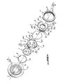
- the invention relates to a synchronizer for a gearbox, essentially comprising a pinion 1, a hub 2, a sleeve 3, a synchronization ring 4, an elastic ring 5 acting as an elastic support member 5 , at least two cones 6 and 7 acting as friction elements, and connecting means, which will be detailed later, to rotate the ring 4 to the hub 2 with a tolerance of angular deflection of limited amplitude.
- the pinion 1 is mounted loosely on a shaft, not shown, which is oriented along the axis X of the figure 1 and on which the hub 2 meanwhile mounted fixed in rotation, the pinion and the hub being both mounted fixed in axial translation on the shaft, that is to say fixed along the axis X.
- the sleeve 3 is mounted fixed in rotation and axially sliding in translation on the hub 2, the sliding of this sleeve being controlled by a fork (not shown) of a gearbox engaged in a groove 39 of the sleeve 3.
- the synchronizing ring 4 is disposed between the hub 2 and the pinion 1, axially movable along the axis X, and carries at its periphery a plurality of teeth 41 which together form a first male toothing 40.
- a plurality of dogs 11 protrude axially from the pinion 1 in the direction of the ring 4, and form a second male toothing 10.
- the inner surface of the sleeve 3 is lined with teeth 31, which are axially cut therein, and which together form a female toothing 30.
- the hub 2 comprises toothed sectors, such as 2AB, 2BC, and 2CA, with the teeth 21 of which are engaged the teeth 31 of the female toothing 30 of the sleeve 3, this meshing allowing this sleeve to be fixed in rotation on the hub 2.
- toothed sectors such as 2AB, 2BC, and 2CA
- the teeth 31 of the sleeve delimit between them interstices 33 and are each completed, opposite the ring 4, by a lance tip profile.
- Each gap 33 of the sleeve 3 is thus bordered by a zone 330 of axial dog retention having, opposite the ring 4, an opening 331 of reduced entry width L331, and an increasing width away from the opening 331.
- the male friction cone 6 is for example made integral in rotation with the pinion 1 by means of axial reliefs 61 carried by this cone 6 and engaged in axial slots 12 of the pinion 1.
- the female friction cone 7 is for example made integral in rotation with the synchronizing ring 4 by means of radial tabs 43 carried by the ring 4 and engaged in axial housings 71 of the female cone 7.
- the elastic ring or annular spring 5 has the function of transmitting to the synchronization ring 4, in a manner that will be described later, an axial elastic biasing during the displacement of the sleeve 3 towards the ring, its rest position to his engagement position.
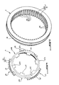
- the connecting means which will be described later, have the function of rotating the ring 4 to the hub 2 with a tolerance T angular deflection of limited amplitude, for example approximately equal to half the distance E ( figure 2 ) between two adjacent teeth 41 of the ring 4.
- the synchronizer proposed by the invention comprises one or more particular pairs of indexing elements which make it possible to ensure, in a very efficient and precise manner, a rotational indexing of the ring 4 with respect to the sleeve 3.
- each pair of indexing elements comprises on the one hand a guide tooth 42, of width L42, which is carried by the ring 4, and on the other hand an axial guide groove 32, of width L32, which is hollowed in the inner surface of the sleeve 3 and which has an opening 321 facing the ring 4.
- each guide tooth 42 is greater than the entry width L331 of the retention zones 331 and less than the width L32 of the guide groove 32, so that each tooth of guide 42 can only fit in a guide groove 32 and not in a retaining zone 331.
- the opening 321 of each guide groove 32 is at least as close to the ring 4 as is the opening 331 of each of the interstices 33 of the sleeve 3.
- the distance between the opening 321 of each guide groove 32 and the corresponding guide tooth 42 of the ring 4 is at most equal to the distance between the opening 331 of each of the interstices 33 of the sleeve 3 and the corresponding tooth 41 of the first male toothing 40.
- the synchronizer of the invention advantageously comprises three identical pairs of indexing elements 32 and 42 of the sleeve 3 relative to the ring 4, including three guide teeth 42 uniformly distributed around the ring 4, and three guide grooves 32 uniformly distributed on the inner surface of the sleeve 3, this arrangement allowing optimal guidance of the teeth 41 in the interstices 33.
- the ring 4 comprises for example three toothed sectors 4A, 4B, and 4C regularly distributed around the periphery of this ring and separated by three free intervals 4AB, 4BC, and 4CA.
- Each of these three toothed sectors 4A, 4B, and 4C preferably carries an even number of teeth 41 of the first male toothing 40, and a guide tooth 42 disposed in the middle of this toothed sector.
- the hub 2 itself comprises a median web 25 and three tooth sectors 2AB, 2BC, and 2CA, regularly distributed around the periphery of the hub and separated by three notches 25A, 25B, and 25C of the mid-web 25.
- Each of the three toothed sectors 2AB, 2BC, and 2CA protrudes axially from the middle web 25 towards the ring 4, and carries the teeth 21 which together form a third male toothing 20 permanently engaged with the female toothing 30 of the sleeve 3.
- the toothing 20 of the hub 2 and the toothing 30 of the sleeve 3 can, as illustrated, be symmetrical with respect to a plane perpendicular to the axis X to allow this hub and this sleeve to cooperate, in a well-known manner. in itself of the skilled person, with a second set of parts not shown but symmetrical other parts illustrated on the figure 1 and therefore comprising a second annular spring, a second ring, a second pair of friction cones, and a second pinion.
- those of the teeth 31 of the sleeve 3 which are arranged opposite the notches 25A, 25B, and 25C of the central web 25 of the hub 2 carry ramps such as 31A and 31C, which form oblique surfaces relative to to the X axis, and which transform a portion of the axial bias resulting from the displacement of the sleeve 3 into a centripetal radial force component applied to the annular spring 5.
- the annular spring 5 opposes this component of radial force, which tends to compress it radially, and offers resistance axial which is transmitted to the ring as an axial stress thereof.
- the connecting means which make it possible to link the ring 4 to the hub 2 in rotation with an angular deflection tolerance of limited amplitude, comprise, for example, the notches 25A, 25B, and 25C of the middle web 25 of the hub 2, and axial indexing reliefs 45A, 45B, and 45C which are carried by the ring 4 and which are angularly deflected in the notches 25A, 25B, and 25C.
- each toothed sector 2AB, 2BC, and 2CA of the hub 2 has a middle portion 2M and two lateral portions 2L axially recessed from the middle portion 2M to form two axial housings 24.
- each toothed sector 4A, 4B, and 4C of the ring 4 faces, by its median part, with a notch 25A, 25B, and 25C of the median veil 25, and can register axially, by its lateral parts, in two adjacent axial housings 24 of the hub 2.
Landscapes
- Engineering & Computer Science (AREA)
- General Engineering & Computer Science (AREA)
- Mechanical Engineering (AREA)
- Mechanical Operated Clutches (AREA)
- Iron Core Of Rotating Electric Machines (AREA)
Claims (10)
- Synchronisierung für ein Getriebe, umfassend: ein Ritzel (1), das frei drehbar auf einer Welle montiert ist; eine Nabe (2), die drehfest auf der Welle montiert ist; eine Hülle (3), die drehfest auf der Nabe (2) montiert ist und axial in Translation zwischen einer vom Ritzel (1) relativ entfernten Ruheposition und mindestens einer zum Ritzel (1) relativ nahen Eingreifposition gleitet; einen Synchronisierring (4), der axial beweglich und zwischen der Nabe (2) und dem Ritzel (1) angeordnet ist; mindestens ein elastisches Stützelement (5), um auf die Synchronisierring (4) durch Verschieben der Hülle (3) eine axiale elastische Belastung zu übertragen; mindestens zwei Reibungselemente (6, 7), um auf progressive und selektive Weise das Ritzel (1) und den Synchronisierring (4) in Drehung zu koppeln, wenn dieser vom elastischen Stützelement (5) eine axiale Belastung erhält; eine Vielzahl von Umfangszähnen (41), die vom Synchronisierring (4) getragen werden und eine erste Einsteckzahnung (40) bilden; eine Vielzahl von axial aus dem Ritzel (1) in Richtung des Ringes (4) vorspringenden Klauen (11), die eine zweite Einsteckzahnung (10) bilden; eine Vielzahl axial in eine Innenfläche der Hülle (3) eingeschnittenen Zähnen (31), die mit einem lanzenspitzartigen Profil gegenüber dem Ring (4) enden und Zwischenräume (33) begrenzen und eine Aufnahmezahnung (30) bilden, die selektiv von der ersten Einsteckzahnung (40) bis zur zweiten Einsteckzahnung (10) beim Übergang der Hülle (3) von der Ruheposition in die Eingreifposition geführt wird, wobei jeder Zwischenraum (33) der Hülle (3) von einer axialen Klauenhaltezone (330) eingesäumt ist, die eine Öffnung (331) von geringer Eingangsbreite (L331) gegenüber dem Ring (4) und eine größer werdende Breite in Entfernung von der Öffnung (331) aufweist; und Verbindungsmittel (25A, 25B, 25C; 45A, 45B, 45C), um den Ring (4) mit der Nabe (2) mit einer Winkelausschlagtoleranz (T) von begrenzter Amplitude drehfest zu verbinden, dadurch gekennzeichnet, dass sie mindestens ein Paar von Elementen (32, 42) zur Indexierung des Rings (4) in Bezug zur Hülle (3) umfasst, wobei jedes Paar von Indexierungselementen einen Führungszahn (42), der vom Ring (4) getragen wird, und eine axiale Führungsnut (32) von bestimmter Länge (L32) umfasst, die in der Innenfläche der Hülle (3) ausgehöhlt ist, und eine zum Ring (4) gewandte Öffnung (321) aufweist, und dass jeder Führungszahn (42) eine Breite (L42) aufweist, die größer als die Eingangsbreite (L331) der Haltezonen (331) und geringer als die Breite (L32) der Führungsnut (32) ist.
- Synchronisierung nach Anspruch 1 oder 2, dadurch gekennzeichnet, dass die Öffnung (321) mindestens einer Führungsnut (32) mindestens ebenso nahe zum Ring (4) wie die Öffnung (331) zu jedem der Zwischenräume (33) der Hülle (3) ist.
- Synchronisierung nach Anspruch 1 oder 2, dadurch gekennzeichnet, dass sie drei identische Paare von Elementen (32, 42) zur Indexierung der Hülle (3) in Bezug zum Ring (4) umfasst, die drei einheitlich um den Ring (4) verteilte Führungszähne (42) und drei einheitlich auf der Innenfläche der Hülle (3) verteilte Führungsnuten (32) einschließen.
- Synchronisierung nach einem der vorhergehenden Ansprüche, dadurch gekennzeichnet, dass die Winkelausschlagtoleranz (T) des Ringes (4) in Bezug zur Nabe (2) mindestens annähernd gleich der Hälfte eines Abstandes (E) zwischen zwei aneinander grenzenden Zähnen (41) des Ringes (4) ist.
- Synchronisierung nach einem der vorhergehenden Ansprüche, dadurch gekennzeichnet, dass der Ring (4) drei Zahnsektoren (4A, 4B, 4C) umfasst, die regelmäßig verteilt und durch drei freie Zwischenräume (4AB, 4BC, 4CA) getrennt sind, wobei jeder der drei Zahnsektoren (4A, 4B, 4C) Zähne (41) der ersten Einsteckzahnung (40) und einen Führungszahn (42) trägt, der vorzugsweise in der Mitte dieses Sektors (4A, 4B, 4C) angeordnet ist.
- Synchronisierung nach einem der vorhergehenden Ansprüche, dadurch gekennzeichnet, dass die Nabe (2) einen Mittelschirm (25) und drei Zahnsektoren (2AB, 2BC, 2CA) umfasst, die regelmäßig verteilt und durch drei Ausschnitte (25A, 25B, 25C) vom Mittelschirm (25) getrennt sind, wobei diese drei Zahnsektoren (25A, 25B, 25C) axial über den Mittelschirm (25) in Richtung des Ringes (4) hinausragen und jeweils Zähne (21) einer dritten Einsteckzahnung (20) tragen, die permanent mit der Aufnahmezahnung (30) der Hülle (3) in Eingriff steht.
- Synchronisierung nach Anspruch 6, dadurch gekennzeichnet, dass das elastische Stützelement (5) eine Ringfeder (5) umfasst, die am Mittelschirm (25) in der Ruheposition der Hülle (3) abgestützt ist und zum Ring (4) durch Einzugsrampen (31A, 31C) gedrückt wird, die von manchen Zähnen (31) der Hülle (3) getragen werden, die gegenüber den Ausschnitten (25A, 25B, 25C) des Mittelschirms (25) der Nabe (2) angeordnet sind, wenn die Hülle (3) in ihre Eingreifposition gedrückt wird.
- Synchronisierung nach Anspruch 6 oder 7, dadurch gekennzeichnet, dass die Verbindungsmittel (25A, 25B, 25C; 45A, 45B, 45C) die Ausschnitte (25A, 25B, 25C) des Mittelschirms (25) der Nabe (2) und axiale Indexierungsreliefs (45A, 45B, 45C) umfassen, die vom Ring (4) getragen werden und in den Ausschnitten (25A, 25B, 25C) ausschlagen.
- Synchronisierung nach einem der Ansprüche 6 bis 8 in Kombination mit Anspruch 5, dadurch gekennzeichnet, dass jeder der Zahnsektoren (2AB, 2BC, 2CA) der Nabe (2) einen Mittelteil (2M) und zwei Seitenteile (2L) aufweist, die axial in Bezug zum Mittelteil (2M) zurückgesetzt sind, um zwei Axiallagerungen (24) zu bilden, und dass jeder Zahnsektor (4A, 4B, 4C) des Ringes (4) einem Ausschnitt (25A, 25B, 25C) des Mittelschirms (25) gegenüber liegt und axial in zwei Axiallagerungen (24) der Nabe (2) eingeschrieben ist.
- Synchronisierung nach einem der vorhergehenden Ansprüche, dadurch gekennzeichnet, dass die Reibungselemente (6, 7) mindestens einen Einsteckreibungskegel (6), der vom Ritzel (1) getragen wird, und einen Aufnahmereibungskegel (7) umfassen, der in Bezug zum Ring (4) drehfest angebracht ist.
Applications Claiming Priority (2)
| Application Number | Priority Date | Filing Date | Title |
|---|---|---|---|
| FR0013554A FR2815682B1 (fr) | 2000-10-23 | 2000-10-23 | Synchroniseur a frottements parasites reduits |
| FR0013554 | 2000-10-23 |
Publications (2)
| Publication Number | Publication Date |
|---|---|
| EP1201952A1 EP1201952A1 (de) | 2002-05-02 |
| EP1201952B1 true EP1201952B1 (de) | 2009-04-29 |
Family
ID=8855630
Family Applications (1)
| Application Number | Title | Priority Date | Filing Date |
|---|---|---|---|
| EP01402699A Expired - Lifetime EP1201952B1 (de) | 2000-10-23 | 2001-10-18 | Synchronisierung mit verringerter, störender Reibung |
Country Status (4)
| Country | Link |
|---|---|
| EP (1) | EP1201952B1 (de) |
| AT (1) | ATE430270T1 (de) |
| DE (1) | DE60138518D1 (de) |
| FR (1) | FR2815682B1 (de) |
Families Citing this family (4)
| Publication number | Priority date | Publication date | Assignee | Title |
|---|---|---|---|---|
| US7121393B1 (en) | 2003-08-11 | 2006-10-17 | Borgwarner Inc. | Segmented synchronizer clutch |
| GB0318805D0 (en) * | 2003-08-11 | 2003-09-10 | Borgwarner Inc | Segmented synchroniser clutch |
| FR2946109B1 (fr) * | 2009-05-29 | 2011-05-20 | Peugeot Citroen Automobiles Sa | Boite de vitesses equipee d'un synchroniseur avec passage en couple controle |
| CN113137436A (zh) * | 2021-05-10 | 2021-07-20 | 扬州意得机械有限公司 | 一种粉末冶金同步器齿毂 |
Family Cites Families (4)
| Publication number | Priority date | Publication date | Assignee | Title |
|---|---|---|---|---|
| FR1378775A (fr) * | 1964-01-09 | 1964-11-13 | Fiat Spa | Perfectionnements apportés aux cônes libres de synchroniseurs, notamment pour boîtes de vitesses de véhicules à moteur |
| DE2510657A1 (de) * | 1975-03-12 | 1976-09-23 | Helmut Droeschel | Zahnkupplung in zahnradwechselgetriebe mit stirnverzahnung und synchronisierung |
| SE502042C2 (sv) * | 1993-11-18 | 1995-07-24 | Volvo Ab | Synkroniseringsanordning i en fordonsväxellåda |
| FR2789139B1 (fr) * | 1999-02-02 | 2001-04-20 | Peugeot Citroen Automobiles Sa | Ensemble synchroniseur pour une transmission d'un vehicule automobile |
-
2000
- 2000-10-23 FR FR0013554A patent/FR2815682B1/fr not_active Expired - Fee Related
-
2001
- 2001-10-18 EP EP01402699A patent/EP1201952B1/de not_active Expired - Lifetime
- 2001-10-18 DE DE60138518T patent/DE60138518D1/de not_active Expired - Lifetime
- 2001-10-18 AT AT01402699T patent/ATE430270T1/de not_active IP Right Cessation
Also Published As
| Publication number | Publication date |
|---|---|
| DE60138518D1 (de) | 2009-06-10 |
| ATE430270T1 (de) | 2009-05-15 |
| FR2815682A1 (fr) | 2002-04-26 |
| EP1201952A1 (de) | 2002-05-02 |
| FR2815682B1 (fr) | 2003-01-31 |
Similar Documents
| Publication | Publication Date | Title |
|---|---|---|
| EP0332497B1 (de) | Wälzlager mit einstellbarer Vorspannung | |
| EP1431845A1 (de) | Uhrgehäuse | |
| FR2619880A1 (fr) | Butee de debrayage, notamment pour vehicules automobiles | |
| EP1214528B1 (de) | Ziehkeilschaltgetriebe | |
| FR2952152A1 (fr) | Ensemble de synchronisation multiple d'une boite de vitesses et boite de vitesses | |
| FR2975455A1 (fr) | Unite de synchronisation d'une boite de vitesses | |
| FR2744503A1 (fr) | Roue de vitesse en deux parties pour boite de vitesses | |
| EP1201952B1 (de) | Synchronisierung mit verringerter, störender Reibung | |
| EP1298340B1 (de) | Synchronisiereinrichtung für Schaltgetriebe von Kraftfahrzeugen | |
| EP0482443B1 (de) | Bremsungsvorrichtung für ein Zahnrad | |
| FR2760261A1 (fr) | Dispositif de synchronisation pour boite de vitesses | |
| FR2472110A1 (fr) | Synchroniseur pour boite de vitesses de vehicule a moteur | |
| EP1026418B1 (de) | Synchronisiereinrichtung für ein Fahrzeuggetriebe | |
| EP1184585B1 (de) | Einrichtung um eine Kugel in der Nabe einer Synchronisiereinrichtung für Kraftfahrzeuge zu halten | |
| JP2004076764A (ja) | 歯車変速装置の同期機構 | |
| WO2018037179A1 (fr) | Dispositif de transmission de couple | |
| WO2018037180A1 (fr) | Dispositif de transmission de couple | |
| EP1072811A1 (de) | Haltevorrichtung für zwei ringförmige Federn der Synchronsperre in einer Synchronisationsnabe geeignet für Synchronisiereinrichtungen bei Kraftfahrzeug-Getrieben | |
| EP1437633B1 (de) | Räderwerk eines Chronographes | |
| EP1643168A1 (de) | Getriebesteuerungseinrichtung für Kraftahrzeuge | |
| FR2818339A1 (fr) | Dispositif de synchronisation compact | |
| EP4065854B1 (de) | Kupplungsmodul | |
| FR2783294A1 (fr) | Synchroniseur simple pour boite de vitesses notamment de vehicule automobile | |
| FR2830301A1 (fr) | Dispositif d'entrainement en rotation alternatif de deux arbres menes montes concentriques a partir d'un seul arbre d'entrainement | |
| WO2018020156A1 (fr) | Dispositif de transmission de couple, notamment pour vehicule automobile |
Legal Events
| Date | Code | Title | Description |
|---|---|---|---|
| PUAI | Public reference made under article 153(3) epc to a published international application that has entered the european phase |
Free format text: ORIGINAL CODE: 0009012 |
|
| AK | Designated contracting states |
Kind code of ref document: A1 Designated state(s): AT BE CH CY DE DK ES FI FR GB GR IE IT LI LU MC NL PT SE TR |
|
| AX | Request for extension of the european patent |
Free format text: AL;LT;LV;MK;RO;SI |
|
| 17P | Request for examination filed |
Effective date: 20020926 |
|
| AKX | Designation fees paid |
Free format text: AT BE CH CY DE DK ES FI FR GB GR IE IT LI LU MC NL PT SE TR |
|
| GRAP | Despatch of communication of intention to grant a patent |
Free format text: ORIGINAL CODE: EPIDOSNIGR1 |
|
| GRAS | Grant fee paid |
Free format text: ORIGINAL CODE: EPIDOSNIGR3 |
|
| GRAA | (expected) grant |
Free format text: ORIGINAL CODE: 0009210 |
|
| AK | Designated contracting states |
Kind code of ref document: B1 Designated state(s): AT BE CH CY DE DK ES FI FR GB GR IE IT LI LU MC NL PT SE TR |
|
| REG | Reference to a national code |
Ref country code: GB Ref legal event code: FG4D Free format text: NOT ENGLISH |
|
| REG | Reference to a national code |
Ref country code: CH Ref legal event code: EP |
|
| REF | Corresponds to: |
Ref document number: 60138518 Country of ref document: DE Date of ref document: 20090610 Kind code of ref document: P |
|
| REG | Reference to a national code |
Ref country code: IE Ref legal event code: FG4D |
|
| NLV1 | Nl: lapsed or annulled due to failure to fulfill the requirements of art. 29p and 29m of the patents act | ||
| PG25 | Lapsed in a contracting state [announced via postgrant information from national office to epo] |
Ref country code: FI Free format text: LAPSE BECAUSE OF FAILURE TO SUBMIT A TRANSLATION OF THE DESCRIPTION OR TO PAY THE FEE WITHIN THE PRESCRIBED TIME-LIMIT Effective date: 20090429 Ref country code: PT Free format text: LAPSE BECAUSE OF FAILURE TO SUBMIT A TRANSLATION OF THE DESCRIPTION OR TO PAY THE FEE WITHIN THE PRESCRIBED TIME-LIMIT Effective date: 20090829 Ref country code: ES Free format text: LAPSE BECAUSE OF FAILURE TO SUBMIT A TRANSLATION OF THE DESCRIPTION OR TO PAY THE FEE WITHIN THE PRESCRIBED TIME-LIMIT Effective date: 20090809 Ref country code: AT Free format text: LAPSE BECAUSE OF FAILURE TO SUBMIT A TRANSLATION OF THE DESCRIPTION OR TO PAY THE FEE WITHIN THE PRESCRIBED TIME-LIMIT Effective date: 20090429 |
|
| REG | Reference to a national code |
Ref country code: GB Ref legal event code: 746 Effective date: 20091012 |
|
| PG25 | Lapsed in a contracting state [announced via postgrant information from national office to epo] |
Ref country code: NL Free format text: LAPSE BECAUSE OF FAILURE TO SUBMIT A TRANSLATION OF THE DESCRIPTION OR TO PAY THE FEE WITHIN THE PRESCRIBED TIME-LIMIT Effective date: 20090429 Ref country code: SE Free format text: LAPSE BECAUSE OF FAILURE TO SUBMIT A TRANSLATION OF THE DESCRIPTION OR TO PAY THE FEE WITHIN THE PRESCRIBED TIME-LIMIT Effective date: 20090729 |
|
| REG | Reference to a national code |
Ref country code: IE Ref legal event code: FD4D |
|
| PG25 | Lapsed in a contracting state [announced via postgrant information from national office to epo] |
Ref country code: IE Free format text: LAPSE BECAUSE OF FAILURE TO SUBMIT A TRANSLATION OF THE DESCRIPTION OR TO PAY THE FEE WITHIN THE PRESCRIBED TIME-LIMIT Effective date: 20090429 Ref country code: DK Free format text: LAPSE BECAUSE OF FAILURE TO SUBMIT A TRANSLATION OF THE DESCRIPTION OR TO PAY THE FEE WITHIN THE PRESCRIBED TIME-LIMIT Effective date: 20090429 |
|
| PLBE | No opposition filed within time limit |
Free format text: ORIGINAL CODE: 0009261 |
|
| STAA | Information on the status of an ep patent application or granted ep patent |
Free format text: STATUS: NO OPPOSITION FILED WITHIN TIME LIMIT |
|
| 26N | No opposition filed |
Effective date: 20100201 |
|
| BERE | Be: lapsed |
Owner name: PEUGEOT CITROEN AUTOMOBILES SA Effective date: 20091031 |
|
| PG25 | Lapsed in a contracting state [announced via postgrant information from national office to epo] |
Ref country code: MC Free format text: LAPSE BECAUSE OF NON-PAYMENT OF DUE FEES Effective date: 20091031 |
|
| REG | Reference to a national code |
Ref country code: CH Ref legal event code: PL |
|
| PG25 | Lapsed in a contracting state [announced via postgrant information from national office to epo] |
Ref country code: GR Free format text: LAPSE BECAUSE OF FAILURE TO SUBMIT A TRANSLATION OF THE DESCRIPTION OR TO PAY THE FEE WITHIN THE PRESCRIBED TIME-LIMIT Effective date: 20090730 Ref country code: LI Free format text: LAPSE BECAUSE OF NON-PAYMENT OF DUE FEES Effective date: 20091031 Ref country code: CH Free format text: LAPSE BECAUSE OF NON-PAYMENT OF DUE FEES Effective date: 20091031 Ref country code: BE Free format text: LAPSE BECAUSE OF NON-PAYMENT OF DUE FEES Effective date: 20091031 |
|
| PG25 | Lapsed in a contracting state [announced via postgrant information from national office to epo] |
Ref country code: IT Free format text: LAPSE BECAUSE OF FAILURE TO SUBMIT A TRANSLATION OF THE DESCRIPTION OR TO PAY THE FEE WITHIN THE PRESCRIBED TIME-LIMIT Effective date: 20090429 |
|
| PG25 | Lapsed in a contracting state [announced via postgrant information from national office to epo] |
Ref country code: LU Free format text: LAPSE BECAUSE OF NON-PAYMENT OF DUE FEES Effective date: 20091018 |
|
| PG25 | Lapsed in a contracting state [announced via postgrant information from national office to epo] |
Ref country code: TR Free format text: LAPSE BECAUSE OF FAILURE TO SUBMIT A TRANSLATION OF THE DESCRIPTION OR TO PAY THE FEE WITHIN THE PRESCRIBED TIME-LIMIT Effective date: 20090429 |
|
| PG25 | Lapsed in a contracting state [announced via postgrant information from national office to epo] |
Ref country code: CY Free format text: LAPSE BECAUSE OF FAILURE TO SUBMIT A TRANSLATION OF THE DESCRIPTION OR TO PAY THE FEE WITHIN THE PRESCRIBED TIME-LIMIT Effective date: 20090429 |
|
| REG | Reference to a national code |
Ref country code: FR Ref legal event code: PLFP Year of fee payment: 16 |
|
| PGFP | Annual fee paid to national office [announced via postgrant information from national office to epo] |
Ref country code: GB Payment date: 20160928 Year of fee payment: 16 |
|
| PGFP | Annual fee paid to national office [announced via postgrant information from national office to epo] |
Ref country code: DE Payment date: 20160922 Year of fee payment: 16 |
|
| REG | Reference to a national code |
Ref country code: FR Ref legal event code: PLFP Year of fee payment: 17 |
|
| PGFP | Annual fee paid to national office [announced via postgrant information from national office to epo] |
Ref country code: FR Payment date: 20170921 Year of fee payment: 17 |
|
| REG | Reference to a national code |
Ref country code: DE Ref legal event code: R119 Ref document number: 60138518 Country of ref document: DE |
|
| GBPC | Gb: european patent ceased through non-payment of renewal fee |
Effective date: 20171018 |
|
| REG | Reference to a national code |
Ref country code: FR Ref legal event code: CA Effective date: 20180312 Ref country code: FR Ref legal event code: CD Owner name: PEUGEOT CITROEN AUTOMOBILES SA, FR Effective date: 20180312 |
|
| PG25 | Lapsed in a contracting state [announced via postgrant information from national office to epo] |
Ref country code: DE Free format text: LAPSE BECAUSE OF NON-PAYMENT OF DUE FEES Effective date: 20180501 Ref country code: GB Free format text: LAPSE BECAUSE OF NON-PAYMENT OF DUE FEES Effective date: 20171018 |
|
| PG25 | Lapsed in a contracting state [announced via postgrant information from national office to epo] |
Ref country code: FR Free format text: LAPSE BECAUSE OF NON-PAYMENT OF DUE FEES Effective date: 20181031 |