EP1201928B1 - Disks for a turbo molecular pump - Google Patents
Disks for a turbo molecular pump Download PDFInfo
- Publication number
- EP1201928B1 EP1201928B1 EP01122335A EP01122335A EP1201928B1 EP 1201928 B1 EP1201928 B1 EP 1201928B1 EP 01122335 A EP01122335 A EP 01122335A EP 01122335 A EP01122335 A EP 01122335A EP 1201928 B1 EP1201928 B1 EP 1201928B1
- Authority
- EP
- European Patent Office
- Prior art keywords
- blades
- discs
- disc
- disks
- component
- Prior art date
- Legal status (The legal status is an assumption and is not a legal conclusion. Google has not performed a legal analysis and makes no representation as to the accuracy of the status listed.)
- Revoked
Links
Images


Classifications
-
- F—MECHANICAL ENGINEERING; LIGHTING; HEATING; WEAPONS; BLASTING
- F04—POSITIVE - DISPLACEMENT MACHINES FOR LIQUIDS; PUMPS FOR LIQUIDS OR ELASTIC FLUIDS
- F04D—NON-POSITIVE-DISPLACEMENT PUMPS
- F04D29/00—Details, component parts, or accessories
- F04D29/40—Casings; Connections of working fluid
- F04D29/52—Casings; Connections of working fluid for axial pumps
- F04D29/54—Fluid-guiding means, e.g. diffusers
- F04D29/541—Specially adapted for elastic fluid pumps
- F04D29/542—Bladed diffusers
-
- F—MECHANICAL ENGINEERING; LIGHTING; HEATING; WEAPONS; BLASTING
- F04—POSITIVE - DISPLACEMENT MACHINES FOR LIQUIDS; PUMPS FOR LIQUIDS OR ELASTIC FLUIDS
- F04D—NON-POSITIVE-DISPLACEMENT PUMPS
- F04D19/00—Axial-flow pumps
- F04D19/02—Multi-stage pumps
- F04D19/04—Multi-stage pumps specially adapted to the production of a high vacuum, e.g. molecular pumps
- F04D19/042—Turbomolecular vacuum pumps
-
- F—MECHANICAL ENGINEERING; LIGHTING; HEATING; WEAPONS; BLASTING
- F04—POSITIVE - DISPLACEMENT MACHINES FOR LIQUIDS; PUMPS FOR LIQUIDS OR ELASTIC FLUIDS
- F04D—NON-POSITIVE-DISPLACEMENT PUMPS
- F04D29/00—Details, component parts, or accessories
- F04D29/26—Rotors specially for elastic fluids
- F04D29/32—Rotors specially for elastic fluids for axial flow pumps
- F04D29/321—Rotors specially for elastic fluids for axial flow pumps for axial flow compressors
-
- F—MECHANICAL ENGINEERING; LIGHTING; HEATING; WEAPONS; BLASTING
- F04—POSITIVE - DISPLACEMENT MACHINES FOR LIQUIDS; PUMPS FOR LIQUIDS OR ELASTIC FLUIDS
- F04D—NON-POSITIVE-DISPLACEMENT PUMPS
- F04D29/00—Details, component parts, or accessories
- F04D29/40—Casings; Connections of working fluid
- F04D29/52—Casings; Connections of working fluid for axial pumps
- F04D29/54—Fluid-guiding means, e.g. diffusers
- F04D29/541—Specially adapted for elastic fluid pumps
- F04D29/542—Bladed diffusers
- F04D29/544—Blade shapes
-
- F—MECHANICAL ENGINEERING; LIGHTING; HEATING; WEAPONS; BLASTING
- F05—INDEXING SCHEMES RELATING TO ENGINES OR PUMPS IN VARIOUS SUBCLASSES OF CLASSES F01-F04
- F05D—INDEXING SCHEME FOR ASPECTS RELATING TO NON-POSITIVE-DISPLACEMENT MACHINES OR ENGINES, GAS-TURBINES OR JET-PROPULSION PLANTS
- F05D2230/00—Manufacture
- F05D2230/50—Building or constructing in particular ways
- F05D2230/54—Building or constructing in particular ways by sheet metal manufacturing
-
- F—MECHANICAL ENGINEERING; LIGHTING; HEATING; WEAPONS; BLASTING
- F05—INDEXING SCHEMES RELATING TO ENGINES OR PUMPS IN VARIOUS SUBCLASSES OF CLASSES F01-F04
- F05D—INDEXING SCHEME FOR ASPECTS RELATING TO NON-POSITIVE-DISPLACEMENT MACHINES OR ENGINES, GAS-TURBINES OR JET-PROPULSION PLANTS
- F05D2300/00—Materials; Properties thereof
- F05D2300/10—Metals, alloys or intermetallic compounds
- F05D2300/17—Alloys
- F05D2300/171—Steel alloys
Definitions
- the invention relates to disks for a turbomolecular pump according to the preamble of the first claim.
- a turbomolecular pump is constructed of rotor and stator discs, which are arranged alternately one behind the other and have blade rings.
- the pumping effect is based on the fact that impulses in the pumping direction are transmitted to the molecules of the gas to be pumped by the blades of the rotor disks.
- the two main pumping properties namely pumping speed and pressure ratio, depend strongly on the speed of the rotor disks.
- the pumping speed increases linearly with the speed and the pressure ratio even exponentially.
- the speed of the rotor must be as high as possible. This places high demands on the blades of the rotor disks with regard to their geometry, mechanical strength and stability.
- Another prerequisite for optimum pumping properties is a minimum thickness of the blades.
- strength considerations play a role. Because of the desired high speed, the centrifugal force acting on the blades, the blade root and the inner diameter of the rotor disks must be kept to a minimum.
- Another criterion for optimum pumping properties is the optical tightness of the individual panes. As a result, a backflow within the disk pack in the axial direction is prevented.
- the milled discs are made of aluminum, as this material is well suited for milling.
- turbomolecular pumps require the pumping of corrosive gases. Since aluminum is not resistant to corrosion, the disks thus produced can only be used in these cases after they have been made corrosion-resistant by an appropriate surface treatment. This makes the manufacture of the blades more expensive and expensive.
- the discs thus produced by punching and bending out of the blades have the serious disadvantage that they are not optically dense. This leads to high pollströmmotheren within the pump.
- Another disadvantage is that the total mass of the blades of a disc is relatively large, based on the radial surface of the support ring. As a result, this is highly loaded by the centrifugal force, which in turn limits the speed of the pump and thus their performance.
- GB-A-1 275 386 shows a disc for turbomolecular pumps which is hollow and composed of two part discs, the part discs each having as many blades as the composite disc.
- US-A-3 477 381 teaches a variant of constructing opaque stator disks.
- the blades of the stator disk are mounted individually in an external retaining ring.
- US-A-4 309 143 deals with the choice of material for the production of stamped discs. It proposes to use material whose ratio of tensile strength to specific gravity is greater than 17 ⁇ 10 3 m and which has a modulus of elasticity of more than 10 ⁇ 10 3 kp / mm 2 . Preferably, a copper-beryllium alloy is proposed. Furthermore, it proposes to vary the blade angle between the pump inlet and outlet.
- So-called coiled blades have a different angle of attack on the blade root than on the blade head.
- the advantageous application thereof in turbomolecular pumps teaches US-A-3,748,055.
- the invention has for its object to develop discs for turbomolecular pumps, which do not have the disadvantages described above.
- the discs are made of corrosion-resistant material and can be produced inexpensively with little effort.
- the optical tightness should be largely guaranteed and the burden by the centrifugal force should be kept within such limits, within which the pump can be operated safely at maximum speed.
- the disks according to the invention make it possible to use corrosion-resistant materials for their production, from which the gas-promoting structure is formed by punching slots and unscrewing the blades from the disk plane.
- the joining of several part disks leads to the optical sealing of the entire disk, whereby backflow is prevented both within a disk and within the entire disk package.
- this design allows to equip the individual part discs with fewer blades than a one-piece disc to achieve the optical tightness.
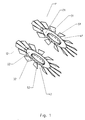
- Fig. 1 shows the two part discs 11 and 12.
- the support rings are denoted by 21 and 22.
- the blades 31 and 32 arranged at an angle to the disk plane are designed so that they form a gas-conveying structure. Between the blades are openings in the form of radially extending slots 41 and 42.
- the two part discs are joined together to form a disc 1 in Fig. 3.
- 2 shows an intermediate stage in which the two partial disks 11 and 12 are already close to each other, but not yet connected to each other.
- the two part discs are joined together with the help of the felts 51 and 52.
- a disk 1 is formed with the inner support ring 2 and the blades 3 arranged at an angle to the disk plane.
- the openings are in the form of radially extending slots 4.
- the blades 3 are made of the blades 31, 32 of the partial disks 11, 12 assembled and designed so that they are visually tight in the axial direction.
- the dividing disks 11, 12 are formed from sheet metal bodies and the blades 31, 32 are produced by punching and subsequent unscrewing from the disk plane.
- Rotor disks consisting of two part disks, were shown in the example. Likewise, more than two part discs can be joined together to form an entire disc. Stator discs may also be composed in the same way within the scope of the invention. As a rule, the blades are then located in the radial direction within the support ring.
Landscapes
- Engineering & Computer Science (AREA)
- Mechanical Engineering (AREA)
- General Engineering & Computer Science (AREA)
- Physics & Mathematics (AREA)
- Geometry (AREA)
- Non-Positive Displacement Air Blowers (AREA)
- Structures Of Non-Positive Displacement Pumps (AREA)
Description
Die Erfindung betrifft Scheiben für eine Turbomolekularpumpe nach dem Oberbegriff des 1. Anspruches.The invention relates to disks for a turbomolecular pump according to the preamble of the first claim.
Eine Turbomolekularpumpe ist aus Rotor- und Statorscheiben aufgebaut, die abwechselnd hintereinander angeordnet sind und Schaufelkränze aufweisen. Die Pumpwirkung beruht darauf, dass durch die Schaufeln der Rotorscheiben Impulse in Pumprichtung auf die Moleküle des zu pumpenden Gases übertragen werden. Die beiden wesentlichen Pumpeigenschaften, nämlich Saugvermögen und Druckverhältnis, hängen stark von der Drehzahl der Rotorscheiben ab. Das Saugvermögen steigt linear mit der Drehzahl an und das Druckverhältnis sogar exponentiell. Um eine optimale Pumpwirkung zu erreichen, muss die Drehzahl des Rotors möglichst hoch sein. Dadurch werden hohe Anforderungen an die Schaufeln der Rotorscheiben betreffend ihrer Geometrie, mechanischen Festigkeit und Stabilität gestellt.A turbomolecular pump is constructed of rotor and stator discs, which are arranged alternately one behind the other and have blade rings. The pumping effect is based on the fact that impulses in the pumping direction are transmitted to the molecules of the gas to be pumped by the blades of the rotor disks. The two main pumping properties, namely pumping speed and pressure ratio, depend strongly on the speed of the rotor disks. The pumping speed increases linearly with the speed and the pressure ratio even exponentially. In order to achieve an optimal pumping effect, the speed of the rotor must be as high as possible. This places high demands on the blades of the rotor disks with regard to their geometry, mechanical strength and stability.
Eine weitere Voraussetzung für optimale Pumpeigenschaften ist eine minimale Dicke der Schaufeln. Neben dem Vorteil eines großen Durchtrittsquerschnittes für das zu pumpende Gas, wodurch das Saugvermögen gesteigert wird, spielen hier Festigkeitsüberlegungen eine Rolle. Wegen der angestrebten hohen Drehzahl muss die Fliehkraft, die auf die Schaufeln, den Schaufelgrund und auf den Innendurchmesser der Rotorscheiben wirkt, auf ein Minimum begrenzt werden.Another prerequisite for optimum pumping properties is a minimum thickness of the blades. In addition to the advantage of a large passage cross-section for the gas to be pumped, whereby the pumping speed is increased, here strength considerations play a role. Because of the desired high speed, the centrifugal force acting on the blades, the blade root and the inner diameter of the rotor disks must be kept to a minimum.
Ein weiteres Kriterium für optimale Pumpeigenschaften ist die optische Dichtheit der einzelnen Scheiben. Dadurch wird eine Rückströmung innerhalb des Scheibenpaketes in axialer Richtung verhindert.Another criterion for optimum pumping properties is the optical tightness of the individual panes. As a result, a backflow within the disk pack in the axial direction is prevented.
Bisher sind im wesentlichen zwei Arten von Scheiben für Turbomolekularpumpen bekannt. Die eine ist aus einer massiven Scheiben hergestellt, in welcher zur Scheibenebene schräge, radial verlaufende Schlitze eingefräst sind. Die andere ist aus Blech gefertigt, wobei durch Stanzen und Herausbiegen von Teilen der Scheibenfläche aus der Scheibenebene Schaufeln gebildet werden.So far, essentially two types of discs for turbomolecular pumps are known. One is made of a solid discs, in which oblique, radially extending slots are milled to the disc plane. The other is made of sheet metal, wherein blades are formed by punching and bending out parts of the disk surface from the disk plane.
Die gefrästen Scheiben werden aus Aluminium hergestellt, da dieser Werkstoff sich gut zum Fräsen eignet. In vielen Anwendungsfällen wird es beim Einsatz von Turbomolekularpumpen erforderlich, korrosive Gase zu fördern. Da Aluminium nicht beständig gegen Korrosion ist, können die so hergestellten Scheiben in diesen Fällen nur eingesetzt werden, nachdem sie durch eine entsprechende Oberflächenbehandlung korrosionsbeständig gemacht wurden. Dadurch wird die Herstellung der Schaufeln aufwendiger und teurer.The milled discs are made of aluminum, as this material is well suited for milling. In many applications, turbomolecular pumps require the pumping of corrosive gases. Since aluminum is not resistant to corrosion, the disks thus produced can only be used in these cases after they have been made corrosion-resistant by an appropriate surface treatment. This makes the manufacture of the blades more expensive and expensive.
Andere Werkstoffe, z. B. hochfester korrosionsbeständiger Stahl, eignen sich wiederum schlecht zum Fräsen. Sie sind aber in Form von Blechen stanz- und verformbar.Other materials, eg. B. high-strength corrosion-resistant steel, are in turn bad for milling. But they are stampable and deformable in the form of sheets.
Die so durch Stanzen und Herausbiegen der Schaufeln hergestellten Scheiben weisen den gravierenden Nachteil auf, dass sie nicht optisch dicht sind. Dies führt zu hohen Rückströmverlusten innerhalb der Pumpe. Ein weiterer Nachteil ist, dass die Gesamtmasse der Schaufeln einer Scheibe relativ groß ist, bezogen auf die radiale Fläche des Tragringes. Dadurch wird dieser durch die Fliehkraft hoch belastet, was wiederum die Drehzahl der Pumpe und somit ihre Leistungsfähigkeit begrenzt.The discs thus produced by punching and bending out of the blades have the serious disadvantage that they are not optically dense. this leads to high Rückströmverlusten within the pump. Another disadvantage is that the total mass of the blades of a disc is relatively large, based on the radial surface of the support ring. As a result, this is highly loaded by the centrifugal force, which in turn limits the speed of the pump and thus their performance.
Die GB-A-1 275 386 zeigt eine Scheibe für Turbomolekularpumpen, welche hohl ist und aus zwei Teilscheiben zusammengesetzt ist, wobei die Teilscheiben jeweils genau so viele Schaufeln aufweisen wie die zusammengesetzte Scheibe besitzt.GB-A-1 275 386 shows a disc for turbomolecular pumps which is hollow and composed of two part discs, the part discs each having as many blades as the composite disc.
Das Dokument Patent Abstracts of Japan, Bd. 007, Nr. 199 und JP 58 098696 A befasst sich mit einem Herstellungsverfahren für Statorscheiben und zielt auf den Schaufelwinkel ab.The document Patent Abstracts of Japan, Vol. 007, No. 199 and JP 58 098696 A is concerned with a manufacturing process for stator disks and aims at the blade angle.
Eine Variante, blickdichte Statorscheiben zu bauen, lehrt die US-A-3 477 381. Die Schaufeln der Statorscheibe werden einzeln in einen außen liegenden Haltering montiert.US-A-3 477 381 teaches a variant of constructing opaque stator disks. The blades of the stator disk are mounted individually in an external retaining ring.
Die US-A-4 309 143 befasst sich mit der Wahl der Materials zur Herstellung von gestanzten Scheiben. Sie schlägt vor, Material zu verwenden, dessen Verhältnis von Dehnfestigkeit zu spezifischem Gewicht größer als 17 x 103m ist und das einen Elastizitätsmodul von mehr als 10 x 103 kp/mm2 beträgt. Bevorzugt wird eine Kupfer-Beryllium-Legierung vorgeschlagen. Weiterhin schlägt sie vor, den Schaufelwinkel zwischen Pumpeneinlass und -auslass zu variieren.US-A-4 309 143 deals with the choice of material for the production of stamped discs. It proposes to use material whose ratio of tensile strength to specific gravity is greater than 17 × 10 3 m and which has a modulus of elasticity of more than 10 × 10 3 kp / mm 2 . Preferably, a copper-beryllium alloy is proposed. Furthermore, it proposes to vary the blade angle between the pump inlet and outlet.
Sogenannte gewendelte Schaufeln haben am Schaufelfuß einen anderen Anstellwinkel als am Schaufelkopf. Die vorteilhafte Anwendung hiervon in Turbomolekularpumpen lehrt die US-A-3 748 055.So-called coiled blades have a different angle of attack on the blade root than on the blade head. The advantageous application thereof in turbomolecular pumps teaches US-A-3,748,055.
Der Erfindung liegt die Aufgabenstellung zugrunde, Scheiben für Turbomolekularpumpen zu entwickeln, welche die oben beschriebenen Nachteile nicht aufweisen. Insbesondere sollen die Scheiben aus korrosionsbeständigem Material bestehen und mit wenig Aufwand und kostengünstig hergestellt werden können. Die optische Dichtheit soll weitgehend gewährleistet sein und die Belastung durch die Fliehkraft soll in solchen Grenzen gehalten werden, innerhalb derer die Pumpe mit maximaler Drehzahl sicher betrieben werden kann.The invention has for its object to develop discs for turbomolecular pumps, which do not have the disadvantages described above. In particular, the discs are made of corrosion-resistant material and can be produced inexpensively with little effort. The optical tightness should be largely guaranteed and the burden by the centrifugal force should be kept within such limits, within which the pump can be operated safely at maximum speed.
Die Aufgabe wird durch die kennzeichnenden Merkmale des 1. Schutzanspruches gelöst. Die Ansprüche 2 und 3 stellen weitere Ausgestaltungsformen der Erfindung dar.The problem is solved by the characterizing features of the first protection claim. Claims 2 and 3 illustrate further embodiments of the invention.
Durch die erfindungsgemäßen Scheiben wird es möglich, zu deren Herstellung korrosionsbeständige Materialien zu verwenden, aus denen die gasfördernde Struktur durch Einstanzen von Schlitzen und Herausdrehen der Schaufeln aus der Scheibenebene gebildet wird. Das Zusammenfügen von mehreren Teilscheiben führt zur optischen Dichtheit der gesamten Scheibe, wodurch Rückströmungen sowohl innerhalb einer Scheibe als auch innerhalb des gesamten Scheibenpaketes verhindert werden. Zudem erlaubt diese Konstruktion, die einzelnen Teilscheiben mit weniger Schaufeln auszustatten als eine einstückige Scheibe, um die optische Dichtheit zu erlangen.The disks according to the invention make it possible to use corrosion-resistant materials for their production, from which the gas-promoting structure is formed by punching slots and unscrewing the blades from the disk plane. The joining of several part disks leads to the optical sealing of the entire disk, whereby backflow is prevented both within a disk and within the entire disk package. In addition, this design allows to equip the individual part discs with fewer blades than a one-piece disc to achieve the optical tightness.
Dadurch wird bei Rotorscheiben die Belastung durch Fliehkraft auf den Schaufelgrund und den Tragring auf ein Minimum begrenzt, so dass durch höhere Drehzahl optimale Pumpeigenschaften erreicht werden können. Gegenüber gefrästen Schaufeln besteht der Vorteil, das die gestanzten Schaufeln deutlich dünner sind und so durch einen größeren Durchtrittsquerschnitt bessere Pumpeigenschaften aufweisen. Auch dieser Tatbestand trägt zur geringeren Belastung durch Fliehkraft bei.As a result, the load on centrifugal force on the blade ground and the support ring is limited to a minimum in rotor disks, so that optimum pumping properties can be achieved by higher rotational speed. Compared with milled blades, there is the advantage that the stamped blades are significantly thinner and thus have better pumping properties due to a larger passage cross section. This fact also contributes to the lower burden of centrifugal force.
Anhand der Figuren 1 - 3 soll die Erfindung am Beispiel einer aus zwei Teilscheiben bestehenden Scheibe zur Montage auf einer Rotorwelle näher erläutert werden.With reference to Figures 1 - 3, the invention will be explained in more detail using the example of a disc consisting of two part discs for mounting on a rotor shaft.
Fig. 1 zeigt die beiden Teilscheiben 11 und 12. Dabei sind die Tragringe mit 21 und 22 bezeichnet. Die schräg zur Scheibenebene angeordneten Schaufeln 31 und 32 sind so gestaltet, dass sie eine gasfördernde Struktur bilden. Zwischen den Schaufeln befinden sich Öffnungen in Form von radial verlaufenden Schlitzen 41 und 42. Die beiden Teilscheiben werden zu einer Scheibe 1 in Fig. 3 zusammengefügt. Die Fig. 2 zeigt ein Zwischenstadium, in dem die beiden Teilscheiben 11 und 12 schon nahe beieinander, jedoch noch nicht miteinander verbunden sind. In Fig. 3 sind die beiden Teilscheiben mit Hilfe der Fügelaschen 51 und 52 zusammengefügt. Es entsteht somit eine Scheibe 1 mit dem inneren Tragring 2 und den schräg zur Scheibenebene angeordneten Schaufeln 3. Zwischen diesen befinden sich die Öffnungen in Form von radial verlaufenden Schlitzen 4. Die Schaufeln 3 sind derart aus den Schaufeln 31, 32 der Teilscheiben 11, 12 zusammgesetzt und gestaltet, dass sie in axialer Richtung optisch dicht sind. Die Teilscheiben 11, 12 sind aus Blechkörpern gebildet und die Schaufeln 31, 32 werden durch Stanzen und anschließendes Herausdrehen aus der Scheibenebene erzeugt.Fig. 1 shows the two
In dem Beispiel wurden Rotorscheiben, bestehend aus zwei Teilscheiben, dargestellt. Ebenso können mehr als zwei Teilscheiben zu einer gesamten Scheibe zusammengefügt werden. Auch Statorscheiben können im Rahmen der Erfindung in der gleichen Art zusammengesetzt sein. In der Regel befinden sich dann die Schaufeln in radialer Richtung innerhalb des Tragringes.Rotor disks, consisting of two part disks, were shown in the example. Likewise, more than two part discs can be joined together to form an entire disc. Stator discs may also be composed in the same way within the scope of the invention. As a rule, the blades are then located in the radial direction within the support ring.
Claims (3)
- Discs (1) for a turbo-molecular pump, which are provided with a support ring (2) and also with blades (3) arranged in a ring-shaped zone obliquely to the disc plane and thus have openings in the form of radially extending slots (4) between the blades, characterised in that they comprise a plurality of component discs (11, 12) joined together in axial direction, wherein these respectively have fewer blades than the assembled disc, and these are joined so that the blades (31, 32) of one component disc respectively completely or partly cover the slots (41, 42) of the following component disc.
- Discs according to Claim 1, characterised in that the component discs (11, 12) are joined so that they are optically impenetrable in axial direction.
- Discs according to Claim 1, characterised in that the component discs (11, 12) are configured as sheet metal bodies and the blades (31, 32) have been formed by stamping and subsequently rotating out of the disc plane.
Applications Claiming Priority (2)
| Application Number | Priority Date | Filing Date | Title |
|---|---|---|---|
| DE10052637 | 2000-10-24 | ||
| DE10052637.3A DE10052637B4 (en) | 2000-10-24 | 2000-10-24 | 02/16/2001 Discs for a turbo molecular pump |
Publications (3)
| Publication Number | Publication Date |
|---|---|
| EP1201928A2 EP1201928A2 (en) | 2002-05-02 |
| EP1201928A3 EP1201928A3 (en) | 2003-04-16 |
| EP1201928B1 true EP1201928B1 (en) | 2006-11-08 |
Family
ID=7660850
Family Applications (1)
| Application Number | Title | Priority Date | Filing Date |
|---|---|---|---|
| EP01122335A Revoked EP1201928B1 (en) | 2000-10-24 | 2001-09-19 | Disks for a turbo molecular pump |
Country Status (4)
| Country | Link |
|---|---|
| US (1) | US20020098088A1 (en) |
| EP (1) | EP1201928B1 (en) |
| JP (1) | JP4056725B2 (en) |
| DE (2) | DE10052637B4 (en) |
Cited By (1)
| Publication number | Priority date | Publication date | Assignee | Title |
|---|---|---|---|---|
| TWI424121B (en) * | 2010-12-10 | 2014-01-21 | Prosol Corp | Turbo molecular pump with improved blade structures |
Families Citing this family (8)
| Publication number | Priority date | Publication date | Assignee | Title |
|---|---|---|---|---|
| DE102006020081A1 (en) * | 2006-04-29 | 2007-10-31 | Pfeiffer Vacuum Gmbh | Rotor or stator disk for a molecular pump |
| GB2440947A (en) * | 2006-08-16 | 2008-02-20 | Boc Group Plc | A stator blade made of at least two stacked sheets |
| DE102007027370A1 (en) * | 2007-06-11 | 2008-12-18 | Wilo Ag | Impeller made of flat material |
| US8221098B2 (en) * | 2009-03-09 | 2012-07-17 | Honeywell International Inc. | Radial turbomolecular pump with electrostatically levitated rotor |
| CN102062121B (en) * | 2010-09-16 | 2013-03-27 | 格兰富水泵(苏州)有限公司 | Axial flow impeller |
| DE102014114326A1 (en) | 2014-10-02 | 2016-04-07 | Pfeiffer Vacuum Gmbh | Method for producing a rotor or stator disk for a vacuum pump and rotor or stator disk for a vacuum pump |
| EP3032106B1 (en) * | 2014-12-08 | 2020-02-12 | Pfeiffer Vacuum Gmbh | Vacuum pump |
| EP3051140B1 (en) * | 2015-01-29 | 2018-01-10 | Pfeiffer Vacuum Gmbh | Stator disc for a vacuum pump |
Family Cites Families (7)
| Publication number | Priority date | Publication date | Assignee | Title |
|---|---|---|---|---|
| DE1071275B (en) * | 1959-12-17 | |||
| DE1503704C3 (en) * | 1966-12-30 | 1972-03-23 | Arthur Pfeiffer Hochvakuumtechnik Gmbh, 6330 Wetzlar | BLADE FOR A WHEEL AND OR GUIDE WHEEL OF A TURBOMOLECULAR PUMP |
| CH499019A (en) * | 1970-04-10 | 1970-11-15 | Balzers Patent Beteilig Ag | Disc for a turbo-molecular vacuum pump |
| DE2035063C3 (en) * | 1970-07-15 | 1974-05-30 | Arthur Pfeiffer-Vakuumtechnik Gmbh, 6330 Wetzlar | Impeller for a turbo molecular pump |
| DE2654055B2 (en) * | 1976-11-29 | 1979-11-08 | Kernforschungsanlage Juelich Gmbh, 5170 Juelich | Rotor and stator disks for turbo molecular pumps |
| DE2717366B2 (en) * | 1977-04-20 | 1979-10-11 | Arthur Pfeiffer-Vakuumtechnik-Wetzlar Gmbh, 6334 Asslar | Impeller for a turbo molecular pump |
| JPS5898696A (en) * | 1981-12-09 | 1983-06-11 | Hitachi Ltd | Stator for molecular pump |
-
2000
- 2000-10-24 DE DE10052637.3A patent/DE10052637B4/en not_active Expired - Lifetime
-
2001
- 2001-09-19 EP EP01122335A patent/EP1201928B1/en not_active Revoked
- 2001-09-19 DE DE50111402T patent/DE50111402D1/en not_active Expired - Lifetime
- 2001-10-05 JP JP2001309958A patent/JP4056725B2/en not_active Expired - Fee Related
- 2001-10-08 US US10/014,141 patent/US20020098088A1/en not_active Abandoned
Cited By (1)
| Publication number | Priority date | Publication date | Assignee | Title |
|---|---|---|---|---|
| TWI424121B (en) * | 2010-12-10 | 2014-01-21 | Prosol Corp | Turbo molecular pump with improved blade structures |
Also Published As
| Publication number | Publication date |
|---|---|
| DE50111402D1 (en) | 2006-12-21 |
| US20020098088A1 (en) | 2002-07-25 |
| EP1201928A3 (en) | 2003-04-16 |
| EP1201928A2 (en) | 2002-05-02 |
| JP2002161889A (en) | 2002-06-07 |
| DE10052637A1 (en) | 2002-05-02 |
| DE10052637B4 (en) | 2021-03-11 |
| JP4056725B2 (en) | 2008-03-05 |
Similar Documents
| Publication | Publication Date | Title |
|---|---|---|
| DE3919529C2 (en) | Vacuum pump | |
| EP1731766B1 (en) | Stator disc for turbomolecular pump | |
| EP2209995A1 (en) | Multi-stage pump rotor for turbo-molecular pump | |
| DE4321173A1 (en) | Refrigerant turbo compressor | |
| WO1997049921A1 (en) | Rotor for a turbomachine with blades insertable into grooves and blades for a rotor | |
| EP1201928B1 (en) | Disks for a turbo molecular pump | |
| DE102012003680A1 (en) | vacuum pump | |
| DE3722164C2 (en) | Turbomolecular pump | |
| EP0363503B1 (en) | Pump stage for a high vacuum pump | |
| DE102008021683A1 (en) | Rotating unit for an axial compressor | |
| EP1498612B1 (en) | Turbo molecular pump | |
| EP1130269B1 (en) | Turbo-molecular pump | |
| EP2480791A1 (en) | Axial-radial turbomachine | |
| DE29715035U1 (en) | Friction vacuum pump | |
| EP1850011B1 (en) | Rotor or stator disc for a molecular pump | |
| WO2000020762A1 (en) | Friction vacuum pump with a stator and a rotor | |
| EP1580435B2 (en) | Turbomolecular pump | |
| DE3402549C2 (en) | ||
| WO2003031823A1 (en) | Axially discharging friction vacuum pump | |
| DE102008058149A1 (en) | Turbo-molecular pump, has rotor element arranged in pump housing, and stator rings surrounding rotor element, where rings exhibit attachment piece extending in longitudinal direction such that adjacent stator ring is arranged within piece | |
| DE102011121223A1 (en) | Turbo compressor i.e. two-stage turbo compressor, for compaction of gaseous medium, has compressor stages arranged on common shaft in force-fit and form-fit manner, and heat exchanger arranged in flow connection between compressor stages | |
| DE102014102681A1 (en) | stator | |
| EP3051140B1 (en) | Stator disc for a vacuum pump | |
| EP3577346B1 (en) | Turbo compressor with integrated flow channels | |
| EP3877653B1 (en) | Multi-stage hydraulic machine |
Legal Events
| Date | Code | Title | Description |
|---|---|---|---|
| PUAI | Public reference made under article 153(3) epc to a published international application that has entered the european phase |
Free format text: ORIGINAL CODE: 0009012 |
|
| AK | Designated contracting states |
Kind code of ref document: A2 Designated state(s): AT BE CH CY DE DK ES FI FR GB GR IE IT LI LU MC NL PT SE TR |
|
| AX | Request for extension of the european patent |
Free format text: AL;LT;LV;MK;RO;SI |
|
| PUAL | Search report despatched |
Free format text: ORIGINAL CODE: 0009013 |
|
| AK | Designated contracting states |
Designated state(s): AT BE CH CY DE DK ES FI FR GB GR IE IT LI LU MC NL PT SE TR |
|
| AX | Request for extension of the european patent |
Extension state: AL LT LV MK RO SI |
|
| RIC1 | Information provided on ipc code assigned before grant |
Ipc: 7F 04D 29/32 B Ipc: 7F 04D 29/54 B Ipc: 7F 04D 19/04 A |
|
| 17P | Request for examination filed |
Effective date: 20030905 |
|
| AKX | Designation fees paid |
Designated state(s): CH DE FR GB IT LI NL |
|
| GRAP | Despatch of communication of intention to grant a patent |
Free format text: ORIGINAL CODE: EPIDOSNIGR1 |
|
| GRAS | Grant fee paid |
Free format text: ORIGINAL CODE: EPIDOSNIGR3 |
|
| GRAA | (expected) grant |
Free format text: ORIGINAL CODE: 0009210 |
|
| AK | Designated contracting states |
Kind code of ref document: B1 Designated state(s): CH DE FR GB IT LI NL |
|
| PG25 | Lapsed in a contracting state [announced via postgrant information from national office to epo] |
Ref country code: NL Free format text: LAPSE BECAUSE OF FAILURE TO SUBMIT A TRANSLATION OF THE DESCRIPTION OR TO PAY THE FEE WITHIN THE PRESCRIBED TIME-LIMIT Effective date: 20061108 |
|
| REG | Reference to a national code |
Ref country code: GB Ref legal event code: FG4D Free format text: NOT ENGLISH |
|
| REG | Reference to a national code |
Ref country code: CH Ref legal event code: EP |
|
| REF | Corresponds to: |
Ref document number: 50111402 Country of ref document: DE Date of ref document: 20061221 Kind code of ref document: P |
|
| GBT | Gb: translation of ep patent filed (gb section 77(6)(a)/1977) |
Effective date: 20070207 |
|
| NLV1 | Nl: lapsed or annulled due to failure to fulfill the requirements of art. 29p and 29m of the patents act | ||
| ET | Fr: translation filed | ||
| PLBI | Opposition filed |
Free format text: ORIGINAL CODE: 0009260 |
|
| 26 | Opposition filed |
Opponent name: EDWARDS LIMITED Effective date: 20070704 |
|
| PLAX | Notice of opposition and request to file observation + time limit sent |
Free format text: ORIGINAL CODE: EPIDOSNOBS2 |
|
| PLAF | Information modified related to communication of a notice of opposition and request to file observations + time limit |
Free format text: ORIGINAL CODE: EPIDOSCOBS2 |
|
| PLBB | Reply of patent proprietor to notice(s) of opposition received |
Free format text: ORIGINAL CODE: EPIDOSNOBS3 |
|
| REG | Reference to a national code |
Ref country code: CH Ref legal event code: PL |
|
| PG25 | Lapsed in a contracting state [announced via postgrant information from national office to epo] |
Ref country code: LI Free format text: LAPSE BECAUSE OF NON-PAYMENT OF DUE FEES Effective date: 20070930 Ref country code: CH Free format text: LAPSE BECAUSE OF NON-PAYMENT OF DUE FEES Effective date: 20070930 |
|
| PGFP | Annual fee paid to national office [announced via postgrant information from national office to epo] |
Ref country code: DE Payment date: 20110906 Year of fee payment: 11 |
|
| PLAB | Opposition data, opponent's data or that of the opponent's representative modified |
Free format text: ORIGINAL CODE: 0009299OPPO |
|
| R26 | Opposition filed (corrected) |
Opponent name: EDWARDS LIMITED Effective date: 20070704 |
|
| REG | Reference to a national code |
Ref country code: DE Ref legal event code: R064 Ref document number: 50111402 Country of ref document: DE Ref country code: DE Ref legal event code: R103 Ref document number: 50111402 Country of ref document: DE |
|
| RDAF | Communication despatched that patent is revoked |
Free format text: ORIGINAL CODE: EPIDOSNREV1 |
|
| RDAG | Patent revoked |
Free format text: ORIGINAL CODE: 0009271 |
|
| STAA | Information on the status of an ep patent application or granted ep patent |
Free format text: STATUS: PATENT REVOKED |
|
| PGFP | Annual fee paid to national office [announced via postgrant information from national office to epo] |
Ref country code: GB Payment date: 20120817 Year of fee payment: 12 |
|
| 27W | Patent revoked |
Effective date: 20120522 |
|
| GBPR | Gb: patent revoked under art. 102 of the ep convention designating the uk as contracting state |
Effective date: 20120522 |
|
| REG | Reference to a national code |
Ref country code: DE Ref legal event code: R107 Ref document number: 50111402 Country of ref document: DE Effective date: 20121227 |
|
| PGFP | Annual fee paid to national office [announced via postgrant information from national office to epo] |
Ref country code: FR Payment date: 20120831 Year of fee payment: 12 |
|
| PGFP | Annual fee paid to national office [announced via postgrant information from national office to epo] |
Ref country code: IT Payment date: 20120927 Year of fee payment: 12 |