EP1201533A2 - Multi-purpose mounting member for bicycle - Google Patents
Multi-purpose mounting member for bicycle Download PDFInfo
- Publication number
- EP1201533A2 EP1201533A2 EP01125786A EP01125786A EP1201533A2 EP 1201533 A2 EP1201533 A2 EP 1201533A2 EP 01125786 A EP01125786 A EP 01125786A EP 01125786 A EP01125786 A EP 01125786A EP 1201533 A2 EP1201533 A2 EP 1201533A2
- Authority
- EP
- European Patent Office
- Prior art keywords
- mounting member
- support portion
- purpose mounting
- pieces
- front support
- Prior art date
- Legal status (The legal status is an assumption and is not a legal conclusion. Google has not performed a legal analysis and makes no representation as to the accuracy of the status listed.)
- Granted
Links
Images


Classifications
-
- B—PERFORMING OPERATIONS; TRANSPORTING
- B62—LAND VEHICLES FOR TRAVELLING OTHERWISE THAN ON RAILS
- B62J—CYCLE SADDLES OR SEATS; AUXILIARY DEVICES OR ACCESSORIES SPECIALLY ADAPTED TO CYCLES AND NOT OTHERWISE PROVIDED FOR, e.g. ARTICLE CARRIERS OR CYCLE PROTECTORS
- B62J15/00—Mud-guards for wheels
- B62J15/02—Fastening means; Stays
Definitions
- This invention generally relates to a multi-purpose mounting member for a bicycle. More specifically, the present invention relates a multi-purpose mounting member for a bicycle that is coupled to the lower tubes of a front suspension fork for supporting bicycle accessory components such as fenders, an electrical control box, a lamp and/or a carrier.
- Bicycling is becoming an increasingly more popular form of recreation as well as a means of transportation. Moreover, bicycling has become a very popular competitive sport for both amateurs and professionals. Whether the bicycle is used for recreation, transportation or competition, the bicycle industry is constantly improving the various components of the bicycle.
- front suspension forks to provide a more comfortable ride.
- the front suspension fork changes the way that various accessories are mounted to the bicycle frame.
- the bicycle brakes must be mounted to the front suspension forks such that they always remain adjacent to the rims.
- the lower tubes of the front suspension forks are provided with mounting posts for mounting the bicycle brake thereto.
- the front suspension forks that are currently being marketed do not provide for any additional accessory components to be mounted thereto. Rather, most of the accessory components are mounted to the frame or upper tubes of the suspension fork of the bicycle in a variety of conventional manners.
- the problem with mounting these accessory components to the bicycle frame or the upper tubes of the suspension fork is that the relationship of the accessory components relative to the wheel and/or ground changes with each compression of the suspension forks.
- One object of the present invention is to provide a multi-purpose mounting member for a bicycle that is coupled to the lower tubes of a front suspension fork for supporting bicycle accessory components such as fenders, an electrical control box, a lamp and/or a carrier.
- Another object of the present invention is to provide a multi-purpose mounting member for a bicycle that has adjustable fenders.
- a multi-purpose mounting member for a bicycle fork comprising a rigid front support portion, a rear support portion and at least one of several accessory components.
- the front rigid support portion has a first end configured to be located adjacent the bicycle fork and a second end with a front accessory attachment portion.
- the rear support portion has a first end coupled to the front support portion to form a mounting space between the front and rear support portions with a portion of the bicycle fork being received in said mounting space.
- At least one of the front and rear support portions is configured with at least one fork mounting portion to be fixedly coupled to the bicycle fork.
- the accessory component is fixedly coupled to the front support portion via the front accessory attachment portion.
- the front and rear support portions adjustably support front and rear fenders and an accessory component.
- accessory component include an electrical control box, a lamp, a rechargeable battery-powered lamp, a dual lamp and/or a carrier.
- the electrical control box preferably includes various conventional components such as a speed sensor, a cycle computer and a rotation sensor for the front wheel, as well as electrical terminals for connection to other electrical devices. Since the internal components of the electrical control box are well known in the bicycle art, these internal components will not be discussed or illustrated in detail herein. Moreover, it will be apparent to those skill in the art from this disclosure that any variety of internal components can be installed in the electrical control box, as needed and/or desired.
- a bicycle 10 (only a portion shown) is illustrated having a frame 12 with a front suspension fork 14 that has a multi-purpose mounting member 16 coupled thereto in accordance with a first embodiment of the present invention as discussed below.
- Bicycle 10 and its various components are well known in the prior art, except for the multi-purpose mounting member 16 of the present invention.
- bicycle 10 and its various components will not be discussed or illustrated in detail herein, except for the components that relate to the present invention.
- the front suspension fork 14 illustrated herein utilizes relatively conventional technology, and thus, will not be discussed or illustrated in detail herein except as needed to describe the present invention.
- the front suspension fork 14 basically includes an attachment component 20, a pair of upper tubes 22 and a pair of lower tubes 24 movably coupled to the upper tubes 22.
- the lower tubes 24 are rigidly coupled together by a bridge 26.
- the attachment component 20 is a conventional member having a post (not shown) mounted within the frame 12 and a lower end coupled to the upper ends of the upper tubes 22.
- the lower ends of the upper tubes 22 are located within the upper ends of the lower tubes 24 with an elastomeric member located therebetween in a conventional manner.
- each of the lower tubes 24 can be provided with a coil spring that engages the lower ends of the upper tubes 22 for providing a shock absorbing effect in a conventional manner.
- the lower tubes 24 also preferably have brake mounting structures (not shown) and wheel mounting flanges 28 at their lower free ends for rotatably mounting the front wheel 30 in a conventional manner.
- the multi-purpose mounting member 16 is preferably mounted on the bridge 26.
- the multi-purpose mounting member 16 can be coupled directly to the lower tubes 24 and/or the bridge 26.
- the multi-purpose mounting member 16 is a one-piece, unitary member.
- the multi-purpose mounting member 16 can be constructed of several pieces as seen in the later embodiments.
- the multi-purpose mounting member 16 can be constructed by casting of a lightweight material, preferably a metallic material such as aluminum.
- the multi-purpose mounting member 16 can be formed by pressing a metal sheet material or any other rigid material that will carry out the present invention.
- the multi-purpose mounting member 16 basically includes a rigid front support portion 40, a rigid rear support portion 42 and a rigid recessed portion 44 that connects the front and rear support portions 40 and 42 together.
- the recessed portion 44 forms a mounting space 46 that is sized to receive the inner side surfaces of the lower tubes 24 and the lower surface of the bridge 26.
- the mounting space 46 is preferably designed to provide a smooth contoured connection with the lower tubes 24 and the bridge 26.
- the mounting space 46 of the multi-purpose mounting member 16 is shaped and arranged to provide a very attractive integrated appearance.
- the front support portion 40 adjustably supports an accessory component such as a front fender 48 or a front fender 48' with integrated lamps 49', while the rear support portion 42 adjustably supports a rear fender 50.
- the fenders 48, 48' and 50 can be constructed of a non-metallic material such as a more flexible plastic material.
- other types of accessory components can be attached to the multi-purpose mounting member 16 by making minor modifications that do not depart from the present invention.
- the front support portion 40 has a first end 52 formed at the recessed portion 44 and a second free end 54 that supports either the fender 48 or the fender 48'.
- the first end 52 of the front support portion 40 flares outwardly relative to the second end 54.
- the front support portion 40 has a convexly curved upper surface 40a and a concaved lower surface 40b relative to the longitudinal center plane of the multi-purpose mounting member 16.
- the front support portion 40 also is curved along the longitudinal axis of the multi-purpose mounting member 16 such that the curvature is similar to that of the bicycle wheel 30.
- the first end 52 flares out in a cone-shaped manner such that the end surface of the first end 52 overlies portions of the lower tubes 24 and the bridge 26 to provide an attractive appearance. Moreover, the first end 52 also preferably extends downwardly farther than the second free end 54.
- a threaded fork mounting hole 60 is formed at the first end 52 for threadedly receiving a fastener such as a fork mounting bolt 62 for securing the multi-purpose mounting member 16 to the bridge 26 as seen in Figures 3 and 4.
- the lower surface 40b of the front support portion 40 is also preferably provided with a pair of threaded holes or nuts 64 that receive bolts 66 for securing fender 48 or 48' thereto.
- the fenders 48 and 48' are adjustably mounted to the front support portion 40 in the longitudinal direction.
- the rear support portion 42 is similar in construction to the front support portion 40. Specifically, the rear support portion 42 has a first end 72 formed at the recessed portion 44 and a second free end 74 extending rearwardly from the first end 72. The first end 72 is flared in the same manner as the first end 52 of the front support portion 40, discussed above. Accordingly, the rear support portion 42 is curved in the transverse direction, as well as the longitudinal direction with an upper surface 42a being convexly curved in both directions and a lower surface 42b being concaved in both directions.
- the first end 72 of the rear support portion 42 is provided with a fork mounting hole 80 that receives the fork mounting bolt 62 therein. More specifically, mounting bolt 62 is inserted through fork mounting hole 80 and a hole 26a of bridge 26, and then threaded into the threaded mounting hole 60 of the front support portion 40 to rigidly secure the multi-purpose mounting member 16 to front suspension fork 14.
- the rear support portion 42 is also provided with a pair of accessory mounting holes or nuts 84 that are threaded to receive bolts 86 for securing the rear fender 50 thereto.
- the rear fender 50 is adjustably mounted to the rear portion 42 in the longitudinal direction.
- the recessed portion 44 is located between the front and rear support portions 40 and 42 for accommodating portions of the lower tubes 24 and the bridge 26 therein. More specifically, the recessed portion 44 is spaced downwardly from the upper surfaces 40a and 42a of the first ends 52 and 72 of the front and rear support portions 40 and 42. Moreover, the sides of the recessed portion 44 are also spaced inwardly from the sides of the first ends 52 and 72 of the front and rear support portions 40 and 42.
- This arrangement provides for an attractive appearance as seen in Figure 2. Moreover, this arrangement allows a single fastener to be utilized to secure the multi-purpose mounting member 16 to the front suspension fork 14.
- fender 48 is preferably provided with an extension portion 90 and a mounting portion or flange 92 with a pair of longitudinally elongated slots 94 that allow the fender 48 to be extended or retracted relative to the multi-purpose mounting member 16 in the longitudinal direction.
- the mounting portion 92 is slightly recessed from the extension portion 90 so that when the fender 48 is fully retracted, the outer surface of the fender 48 forms a smooth contiguous surface with the upper surface 40a of the support portion 40 to form a smooth surface therebetween.
- the alternate fender 48' with the lamps 49' also has an extension portion 90' and a mounting portion or flange 92' a pair of elongated holes or slots 94'. These elongated holes or slots 94' extend in the longitudinal direction to allow for the fender 48' to be extended and/or retracted relative to the multi-purpose mounting member 16 in the longitudinal direction.
- the rear fender 50 has similar structure to the front fender 48. Specifically, the rear fender 50 has an extension portion 96 and a mounting portion 98 with a pair of elongated mounting holes or slots 99. The rear fender is also adjustable in the longitudinal direction so that the rear fender 50 can be retracted or extended relative to the multi-purpose mounting member 16 in the longitudinal direction.
- a multi-purpose mounting member 116 in accordance with a second embodiment is illustrated in accordance with the present invention.
- This embodiment is substantially similar to the first embodiment except that the multi-purpose mounting member 116 is constructed of two pieces, e.g., a holder or first piece 116a and a cover or second piece 116b.
- the plastic cover 116b is molded to substantially the same shape as the multi-purpose mounting member 16 of the first embodiment.
- the multi-purpose mounting member 116 has a rigid holder 116a, which is preferably constructed of a one-piece, unitary metallic member.
- the holder 116a acts as a support for the cover 116b.
- This embodiment also differs from the first embodiment in that the cover 116b and the holder 116a are also fastened to the lower tubes 124 of a modified front suspension fork 114 by additional fork mounting bolts 162'.
- the upper surface of the cover 116b has a recess 141b for attaching the various accessory components (an electrical control box 149, a lamp 151, a rechargeable battery-powered lamp 153 and a dual lamp 155 with a carrier 157) to the top of the fender 148.
- the various accessory components can be fastened by bolts 166 to the multi-purpose member 116 in accordance with this embodiment of the present invention.
- the rigid holder 116a is a metallic member that basically includes a rigid front support portion 140a, a rigid rear support portion 142a and a rigid attachment portion 144a.
- the attachment portion 144a has a pair of mounting flanges 146a with holes 160a to be attached to the bridge 126 by bolt 162 and nut 163.
- Each of the front and rear support portions 140a and 142a also have a pair of mounting flanges 147a and 147b with holes 160a' for attaching to the lower tubes 124 via bolts 162'.
- the front support portion 140a adjustably supports the front fender 148 and an accessory component such as the electrical control box 149, the lamp 151, the rechargeable battery-powered lamp 153, the dual lamp 155 and/or the carrier 157, while the rear support portion 142a adjustably supports the rear fender 150.
- the fenders 148 and 150 can be constructed of a non-metallic material such as a more flexible plastic material.
- other types of accessory components can be attached to the multi-purpose mounting member 116 by making minor modifications that do not depart from the present invention.
- the front support portion 140a has a first end 152a formed at the attachment portion 144a and a second free end 154a that supports the fender 148 and at least one accessory component.
- the front support portion 140a has a convexly curved upper surface and a concaved lower surface in a transverse direction relative to the longitudinal center plane of the multi-purpose mounting member 116.
- the front support portion 140a also is curved along the longitudinal axis of the multi-purpose mounting member 116 such that the curvature is similar to that of the bicycle wheel 30.
- the multi-purpose mounting member 116 is especially designed to support both the fenders 148 and 150 and at least one accessory component via bolts 162.
- the accessory components other than the fenders 148 and 150 include, but are not limited to the electrical control box 149, the lamp 151, the rechargeable battery-powered lamp 153 and the dual lamp 155 with the carrier 157.
- the electrical control box 149 preferably includes various conventional components such as a speed sensor, a cycle computer and a rotation sensor for the front wheel 30, as well as electrical terminals for connection to other electrical devices. Since the internal components of the electrical control box 149 are well known in the bicycle art, these internal components will not be discussed or illustrated in detail herein. Moreover, it will be apparent to those skill in the art from this disclosure that any variety of internal components can be installed in the electrical control box 149, as needed and/or desired.
- the rechargeable battery-powered lamp 153 has a battery 153' that is electrically wired to a dynamo that produces AC voltage for charging the battery 153'.
- the battery 153' is also preferably electrically wired to other bicycle devices, such as a cycle computer, electric shifters, electric motors etc., for supplying DC voltage thereto.
- the carrier 157 has elastic netting 159 coupled thereto such that items can be held on the top surface of the carrier 157 beneath the elastic netting 159.
- each of the accessory components has threaded holes for receiving bolts 166.
- mounting holes 164a of the front support portion 140a of the multi-purpose mounting member 116 do not have to be threaded for mounting the accessory components to the front portion 140a of the multi-purpose mounting member 116.
- the rear support portion 142a is similar in construction to the front support portion 140a. Specifically, the rear support portion 142a has a first end 172a formed at the attachment portion 144a and a second free end 174a extending rearwardly from the first end 172a. Accordingly, the rear support portion 142a is curved in the transverse direction, as well as the longitudinal direction with the upper surface being convexly curved in both directions and the lower surface being concaved in both directions.
- the rear support portion 142a is also provided with a pair of accessory mounting holes 184b that are threaded to receive bolts 186 for securing the rear fender 150 thereto.
- the rear fender 150 is adjustably mounted to the rear portions 142a in the longitudinal direction.
- Fender 148 is preferably provided with an extension portion 190 and a mounting portion or flange 192 with a pair of longitudinally elongated slots 194 that allow the fender 148 to be extended or retracted relative to the multi-purpose mounting member 116 in the longitudinal direction.
- the rear fender 150 has similar structure to the front fender 148. Specifically, the rear fender 150 has an extension portion 196 and a mounting portion 198 with a pair of elongated mounting holes or slots 199. The rear fender is also adjustable in the longitudinal direction so that the rear fender 150 can be retracted or extended relative to the multi-purpose mounting member 116 in the longitudinal direction.
- the cover 116b basically includes a flexible front support portion 140b, a flexible rear support portion 142b and a flexible recessed portion 144b that connects the front and rear support portions 140b and 142b together.
- the recessed portion 144b forms a mounting space 146b that is sized to receive the inner side surfaces of the lower tubes 124 and the lower surface of the bridge 126.
- the mounting space 146b is preferably designed to provide a smooth contoured connection with the lower tubes 124 and the bridge 126.
- the mounting space 146b of the cover 116b is shaped and arranged to provide a very attractive integrated appearance.
- the cover 116b has a plurality of mounting holes 160b that align with the mounting holes 160a of the rigid holder 116a such that the cover 116b is fastened between the front suspension fork 14 and the holder 116a.
- cover 116b has a recess 141b with a pair of holes 164b that align with the holes 164a of the holder 116a for receiving bolts 166 therethrough.
- the rear support portion 142b has a pair of threaded mounting holes or nuts 184b that are threaded to receive bolts 168 for securing the rear fender 150 thereto.
- the rear fender 150 is adjustably mounted to the rear portion 142b in a longitudinal direction.
- a multi-purpose mounting member 216 is illustrated in accordance with the third embodiment of the present invention.
- This embodiment is a further modification of the second embodiment in that the holder 216a and the cover 216b of this third embodiment have each been split into two pieces.
- this third embodiment will not be discussed in detail herein. Rather, it will be apparent to those skilled in the art from this disclosure that the identical or similar structures of this embodiment function in an identical or similar manner as in the first and second embodiments.
- the rigid holder 216a is a two piece metallic member that basically includes a rigid front support portion 240a, which is substantially identical to front support portion 140a, and a rigid rear support portion 242a, which is substantially identical to rear support portion 142a.
- the cover 216b is a two piece plastic member that basically includes a flexible front support portion 240b, which is substantially identical to front support portion 140b, and a flexible rear support portion 242b, which is substantially identical to rear support portion 142b.
- the holder 216a acts as a support for the cover 216b in the same manner as the second embodiment discussed above.
- the multi-purpose mounting member 216 is especially designed to adjustable support both the fenders 248 and 255 and fixedly support at least one accessory component via bolts 262.
- the accessory components other than the fenders 248 and 250 include, but are not limited to, the accessory components of the second embodiment, e.g., the electrical control box 149, the lamp 151, the rechargeable lamp 153 and the dual lamp 155 with the carrier 157 with elastic netting 159.
Landscapes
- Engineering & Computer Science (AREA)
- Mechanical Engineering (AREA)
- Motorcycle And Bicycle Frame (AREA)
- Lighting Device Outwards From Vehicle And Optical Signal (AREA)
- Axle Suspensions And Sidecars For Cycles (AREA)
Abstract
Description
- This invention generally relates to a multi-purpose mounting member for a bicycle. More specifically, the present invention relates a multi-purpose mounting member for a bicycle that is coupled to the lower tubes of a front suspension fork for supporting bicycle accessory components such as fenders, an electrical control box, a lamp and/or a carrier.
- Bicycling is becoming an increasingly more popular form of recreation as well as a means of transportation. Moreover, bicycling has become a very popular competitive sport for both amateurs and professionals. Whether the bicycle is used for recreation, transportation or competition, the bicycle industry is constantly improving the various components of the bicycle.
- In particular, many of the new off-road bicycles have front suspension forks to provide a more comfortable ride. The front suspension fork changes the way that various accessories are mounted to the bicycle frame. For example, the bicycle brakes must be mounted to the front suspension forks such that they always remain adjacent to the rims. Accordingly, the lower tubes of the front suspension forks are provided with mounting posts for mounting the bicycle brake thereto. However, the front suspension forks that are currently being marketed do not provide for any additional accessory components to be mounted thereto. Rather, most of the accessory components are mounted to the frame or upper tubes of the suspension fork of the bicycle in a variety of conventional manners. The problem with mounting these accessory components to the bicycle frame or the upper tubes of the suspension fork is that the relationship of the accessory components relative to the wheel and/or ground changes with each compression of the suspension forks.
- In view of the above, there exists a need for a multi-purpose mounting member for bicycle which overcomes the above mentioned problems in the prior art. This invention addresses this need in the prior art as well as other needs, which will become apparent to those skilled in the art from this disclosure.
- One object of the present invention is to provide a multi-purpose mounting member for a bicycle that is coupled to the lower tubes of a front suspension fork for supporting bicycle accessory components such as fenders, an electrical control box, a lamp and/or a carrier.
- Another object of the present invention is to provide a multi-purpose mounting member for a bicycle that has adjustable fenders.
- The foregoing objects can basically be attained by providing a multi-purpose mounting member for a bicycle fork comprising a rigid front support portion, a rear support portion and at least one of several accessory components. The front rigid support portion has a first end configured to be located adjacent the bicycle fork and a second end with a front accessory attachment portion. The rear support portion has a first end coupled to the front support portion to form a mounting space between the front and rear support portions with a portion of the bicycle fork being received in said mounting space. At least one of the front and rear support portions is configured with at least one fork mounting portion to be fixedly coupled to the bicycle fork. The accessory component is fixedly coupled to the front support portion via the front accessory attachment portion.
- In accordance with certain aspects of the present invention, the front and rear support portions adjustably support front and rear fenders and an accessory component. Examples of some accessory component include an electrical control box, a lamp, a rechargeable battery-powered lamp, a dual lamp and/or a carrier.
- In accordance with a preferred aspect of the present invention, the electrical control box preferably includes various conventional components such as a speed sensor, a cycle computer and a rotation sensor for the front wheel, as well as electrical terminals for connection to other electrical devices. Since the internal components of the electrical control box are well known in the bicycle art, these internal components will not be discussed or illustrated in detail herein. Moreover, it will be apparent to those skill in the art from this disclosure that any variety of internal components can be installed in the electrical control box, as needed and/or desired.
- These and other objects, features, aspects and advantages of the present invention will become apparent to those skilled in the art from the following detailed description, which, taken in conjunction with the annexed drawings, discloses a preferred embodiment of the present invention.
- Referring now to the attached drawings which form a part of this original disclosure:
- Figure 1 is a side elevational view of a bicycle with a multi-purpose mounting member coupled thereto in accordance with a first embodiment of the present invention;
- Figure 2 is a perspective view of the front portion of the bicycle frame with a front suspension fork and the multi-purpose mounting member in accordance with the first embodiment of the present invention;
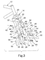
- Figure 3 is an exploded perspective view of the front portion of the bicycle frame, the multi-purpose mounting member and an accessory component (fender) in accordance with the first embodiment of the present invention;
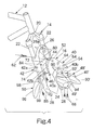
- Figure 4 is an exploded perspective view of the front portion of the bicycle frame, the multi-purpose mounting member and an accessory component (fender with integrated lamps) in accordance with the first embodiment of the present invention;
- Figure 5 is a perspective view of the front portion of the bicycle frame with a front suspension fork, a multi-purpose mounting member and an electrical control box in accordance with a second embodiment of the present invention;
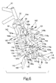
- Figure 6 is an exploded perspective view of the front portion of the bicycle frame, the multi-purpose mounting member and an accessory component (fender and a separate lamp) in accordance with the second embodiment of a present invention;
- Figure 7 is an exploded perspective view of the front portion of the bicycle frame, the multi-purpose mounting member and an accessory component (fender and an alternate separate lamp) in accordance with the second embodiment of the present invention;
- Figure 8 is an exploded perspective view of the front portion of the bicycle frame, the multi-purpose mounting member and an accessory component (fender, a separate dual lamp and a carrier) in accordance with the second embodiment of the present invention;
- Figure 9 is a perspective view of the front portion of the bicycle frame with a front suspension fork, a multi-purpose mounting member and an electrical control box in accordance with a third embodiment of the present invention;
- Figure 10 is an exploded perspective view of the front portion of the bicycle frame, the multi-purpose mounting member and an accessory component (fender and a separate lamp) in accordance with the third embodiment of the present invention;
- Figure 11 is an exploded perspective view of the front portion of the bicycle frame, the multi-purpose mounting member and an accessory component (fender and an alternate separate lamp) in accordance with the third embodiment of the present invention; and
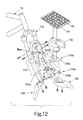
- Figure 12 is an exploded perspective view of the front portion of the bicycle frame, the multi-purpose mounting member and an accessory component (fender, a separate dual lamp and a carrier) in accordance with the third embodiment of the present invention.
-
- Referring initially to Figure 1, a bicycle 10 (only a portion shown) is illustrated having a
frame 12 with afront suspension fork 14 that has amulti-purpose mounting member 16 coupled thereto in accordance with a first embodiment of the present invention as discussed below.Bicycle 10 and its various components are well known in the prior art, except for themulti-purpose mounting member 16 of the present invention. Thus,bicycle 10 and its various components will not be discussed or illustrated in detail herein, except for the components that relate to the present invention. - As used herein, the following directional terms "forward, rearward, upward, above, downward, vertical, horizontal, below and transverse" as well as any other similar directional terms refer to those directions of a bicycle in its normal riding position, with the
multi-purpose mounting member 16 attached thereto. Accordingly, these terms, as utilized to describe themulti-purpose mounting member 16 in the claims, should be interpreted relative tobicycle 10 in its normal riding position. - Referring now to Figure 2, the
front suspension fork 14 illustrated herein utilizes relatively conventional technology, and thus, will not be discussed or illustrated in detail herein except as needed to describe the present invention. Basically, thefront suspension fork 14 basically includes anattachment component 20, a pair ofupper tubes 22 and a pair oflower tubes 24 movably coupled to theupper tubes 22. Thelower tubes 24 are rigidly coupled together by abridge 26. Theattachment component 20 is a conventional member having a post (not shown) mounted within theframe 12 and a lower end coupled to the upper ends of theupper tubes 22. The lower ends of theupper tubes 22 are located within the upper ends of thelower tubes 24 with an elastomeric member located therebetween in a conventional manner. For example, each of thelower tubes 24 can be provided with a coil spring that engages the lower ends of theupper tubes 22 for providing a shock absorbing effect in a conventional manner. Thelower tubes 24 also preferably have brake mounting structures (not shown) andwheel mounting flanges 28 at their lower free ends for rotatably mounting thefront wheel 30 in a conventional manner. - The
multi-purpose mounting member 16 is preferably mounted on thebridge 26. Of course, themulti-purpose mounting member 16 can be coupled directly to thelower tubes 24 and/or thebridge 26. In the first embodiment, themulti-purpose mounting member 16 is a one-piece, unitary member. However, themulti-purpose mounting member 16 can be constructed of several pieces as seen in the later embodiments. In this embodiment, themulti-purpose mounting member 16 can be constructed by casting of a lightweight material, preferably a metallic material such as aluminum. Alternatively, themulti-purpose mounting member 16 can be formed by pressing a metal sheet material or any other rigid material that will carry out the present invention. - In this embodiment, the multi-purpose mounting
member 16 basically includes a rigidfront support portion 40, a rigidrear support portion 42 and a rigid recessedportion 44 that connects the front andrear support portions portion 44 forms a mountingspace 46 that is sized to receive the inner side surfaces of thelower tubes 24 and the lower surface of thebridge 26. As explained below, the mountingspace 46 is preferably designed to provide a smooth contoured connection with thelower tubes 24 and thebridge 26. In other words, the mountingspace 46 of the multi-purpose mountingmember 16 is shaped and arranged to provide a very attractive integrated appearance. - Referring to Figures 3 and 4, the
front support portion 40 adjustably supports an accessory component such as afront fender 48 or a front fender 48' with integrated lamps 49', while therear support portion 42 adjustably supports arear fender 50. Thefenders member 16 by making minor modifications that do not depart from the present invention. - The
front support portion 40 has afirst end 52 formed at the recessedportion 44 and a secondfree end 54 that supports either thefender 48 or the fender 48'. Thefirst end 52 of thefront support portion 40 flares outwardly relative to thesecond end 54. More specifically, thefront support portion 40 has a convexly curvedupper surface 40a and a concavedlower surface 40b relative to the longitudinal center plane of the multi-purpose mountingmember 16. Preferably, thefront support portion 40 also is curved along the longitudinal axis of the multi-purpose mountingmember 16 such that the curvature is similar to that of thebicycle wheel 30. Thefirst end 52 flares out in a cone-shaped manner such that the end surface of thefirst end 52 overlies portions of thelower tubes 24 and thebridge 26 to provide an attractive appearance. Moreover, thefirst end 52 also preferably extends downwardly farther than the secondfree end 54. - A threaded
fork mounting hole 60 is formed at thefirst end 52 for threadedly receiving a fastener such as afork mounting bolt 62 for securing the multi-purpose mountingmember 16 to thebridge 26 as seen in Figures 3 and 4. - The
lower surface 40b of thefront support portion 40 is also preferably provided with a pair of threaded holes or nuts 64 that receivebolts 66 for securingfender 48 or 48' thereto. Thefenders 48 and 48' are adjustably mounted to thefront support portion 40 in the longitudinal direction. - The
rear support portion 42 is similar in construction to thefront support portion 40. Specifically, therear support portion 42 has afirst end 72 formed at the recessedportion 44 and a secondfree end 74 extending rearwardly from thefirst end 72. Thefirst end 72 is flared in the same manner as thefirst end 52 of thefront support portion 40, discussed above. Accordingly, therear support portion 42 is curved in the transverse direction, as well as the longitudinal direction with anupper surface 42a being convexly curved in both directions and alower surface 42b being concaved in both directions. - The
first end 72 of therear support portion 42 is provided with afork mounting hole 80 that receives thefork mounting bolt 62 therein. More specifically, mountingbolt 62 is inserted throughfork mounting hole 80 and ahole 26a ofbridge 26, and then threaded into the threaded mountinghole 60 of thefront support portion 40 to rigidly secure the multi-purpose mountingmember 16 tofront suspension fork 14. - The
rear support portion 42 is also provided with a pair of accessory mounting holes or nuts 84 that are threaded to receivebolts 86 for securing therear fender 50 thereto. Therear fender 50 is adjustably mounted to therear portion 42 in the longitudinal direction. - The recessed
portion 44 is located between the front andrear support portions lower tubes 24 and thebridge 26 therein. More specifically, the recessedportion 44 is spaced downwardly from theupper surfaces rear support portions portion 44 are also spaced inwardly from the sides of the first ends 52 and 72 of the front andrear support portions member 16 to thefront suspension fork 14. - Referring again to Figures 3 and 4,
fender 48 is preferably provided with anextension portion 90 and a mounting portion orflange 92 with a pair of longitudinallyelongated slots 94 that allow thefender 48 to be extended or retracted relative to the multi-purpose mountingmember 16 in the longitudinal direction. Preferably, the mountingportion 92 is slightly recessed from theextension portion 90 so that when thefender 48 is fully retracted, the outer surface of thefender 48 forms a smooth contiguous surface with theupper surface 40a of thesupport portion 40 to form a smooth surface therebetween. Likewise, the alternate fender 48' with the lamps 49' also has an extension portion 90' and a mounting portion or flange 92' a pair of elongated holes or slots 94'. These elongated holes or slots 94' extend in the longitudinal direction to allow for the fender 48' to be extended and/or retracted relative to the multi-purpose mountingmember 16 in the longitudinal direction. - The
rear fender 50 has similar structure to thefront fender 48. Specifically, therear fender 50 has anextension portion 96 and a mountingportion 98 with a pair of elongated mounting holes orslots 99. The rear fender is also adjustable in the longitudinal direction so that therear fender 50 can be retracted or extended relative to the multi-purpose mountingmember 16 in the longitudinal direction. - Referring now to Figures 5-8, a multi-purpose mounting
member 116 in accordance with a second embodiment is illustrated in accordance with the present invention. This embodiment is substantially similar to the first embodiment except that the multi-purpose mountingmember 116 is constructed of two pieces, e.g., a holder or first piece 116a and a cover orsecond piece 116b. - In particular, the
plastic cover 116b is molded to substantially the same shape as the multi-purpose mountingmember 16 of the first embodiment. However, the multi-purpose mountingmember 116 has a rigid holder 116a, which is preferably constructed of a one-piece, unitary metallic member. The holder 116a acts as a support for thecover 116b. This embodiment also differs from the first embodiment in that thecover 116b and the holder 116a are also fastened to thelower tubes 124 of a modifiedfront suspension fork 114 by additional fork mounting bolts 162'. Moreover, the upper surface of thecover 116b has arecess 141b for attaching the various accessory components (anelectrical control box 149, alamp 151, a rechargeable battery-poweredlamp 153 and adual lamp 155 with a carrier 157) to the top of thefender 148. As seen in Figures 6-8, the various accessory components (theelectrical control box 149, thelamp 151, the rechargeable battery-poweredlamp 153 and thedual lamp 155 with the carrier 157) can be fastened bybolts 166 to themulti-purpose member 116 in accordance with this embodiment of the present invention. - In this embodiment, the rigid holder 116a is a metallic member that basically includes a rigid
front support portion 140a, a rigid rear support portion 142a and arigid attachment portion 144a. Theattachment portion 144a has a pair of mountingflanges 146a withholes 160a to be attached to thebridge 126 bybolt 162 andnut 163. Each of the front andrear support portions 140a and 142a also have a pair of mountingflanges 147a and 147b withholes 160a' for attaching to thelower tubes 124 via bolts 162'. - The
front support portion 140a adjustably supports thefront fender 148 and an accessory component such as theelectrical control box 149, thelamp 151, the rechargeable battery-poweredlamp 153, thedual lamp 155 and/or thecarrier 157, while the rear support portion 142a adjustably supports therear fender 150. Thefenders member 116 by making minor modifications that do not depart from the present invention. - The
front support portion 140a has a first end 152a formed at theattachment portion 144a and a secondfree end 154a that supports thefender 148 and at least one accessory component. Thefront support portion 140a has a convexly curved upper surface and a concaved lower surface in a transverse direction relative to the longitudinal center plane of the multi-purpose mountingmember 116. Preferably, thefront support portion 140a also is curved along the longitudinal axis of the multi-purpose mountingmember 116 such that the curvature is similar to that of thebicycle wheel 30. - In the second embodiment, the multi-purpose mounting
member 116 is especially designed to support both thefenders bolts 162. The accessory components other than thefenders electrical control box 149, thelamp 151, the rechargeable battery-poweredlamp 153 and thedual lamp 155 with thecarrier 157. - The
electrical control box 149 preferably includes various conventional components such as a speed sensor, a cycle computer and a rotation sensor for thefront wheel 30, as well as electrical terminals for connection to other electrical devices. Since the internal components of theelectrical control box 149 are well known in the bicycle art, these internal components will not be discussed or illustrated in detail herein. Moreover, it will be apparent to those skill in the art from this disclosure that any variety of internal components can be installed in theelectrical control box 149, as needed and/or desired. - The rechargeable battery-powered
lamp 153 has a battery 153' that is electrically wired to a dynamo that produces AC voltage for charging the battery 153'. The battery 153' is also preferably electrically wired to other bicycle devices, such as a cycle computer, electric shifters, electric motors etc., for supplying DC voltage thereto. Preferably, thecarrier 157 haselastic netting 159 coupled thereto such that items can be held on the top surface of thecarrier 157 beneath theelastic netting 159. Preferably, each of the accessory components has threaded holes for receivingbolts 166. Thus, mountingholes 164a of thefront support portion 140a of the multi-purpose mountingmember 116 do not have to be threaded for mounting the accessory components to thefront portion 140a of the multi-purpose mountingmember 116. - The rear support portion 142a is similar in construction to the
front support portion 140a. Specifically, the rear support portion 142a has afirst end 172a formed at theattachment portion 144a and a secondfree end 174a extending rearwardly from thefirst end 172a. Accordingly, the rear support portion 142a is curved in the transverse direction, as well as the longitudinal direction with the upper surface being convexly curved in both directions and the lower surface being concaved in both directions. - The rear support portion 142a is also provided with a pair of
accessory mounting holes 184b that are threaded to receivebolts 186 for securing therear fender 150 thereto. Therear fender 150 is adjustably mounted to the rear portions 142a in the longitudinal direction. -
Fender 148 is preferably provided with anextension portion 190 and a mounting portion orflange 192 with a pair of longitudinallyelongated slots 194 that allow thefender 148 to be extended or retracted relative to the multi-purpose mountingmember 116 in the longitudinal direction. - The
rear fender 150 has similar structure to thefront fender 148. Specifically, therear fender 150 has anextension portion 196 and a mountingportion 198 with a pair of elongated mounting holes orslots 199. The rear fender is also adjustable in the longitudinal direction so that therear fender 150 can be retracted or extended relative to the multi-purpose mountingmember 116 in the longitudinal direction. - In this embodiment, the
cover 116b basically includes a flexiblefront support portion 140b, a flexiblerear support portion 142b and a flexible recessedportion 144b that connects the front andrear support portions portion 144b forms a mountingspace 146b that is sized to receive the inner side surfaces of thelower tubes 124 and the lower surface of thebridge 126. As explained below, the mountingspace 146b is preferably designed to provide a smooth contoured connection with thelower tubes 124 and thebridge 126. In other words, the mountingspace 146b of thecover 116b is shaped and arranged to provide a very attractive integrated appearance. - The
cover 116b has a plurality of mountingholes 160b that align with the mountingholes 160a of the rigid holder 116a such that thecover 116b is fastened between thefront suspension fork 14 and the holder 116a. As mentioned above,cover 116b has arecess 141b with a pair ofholes 164b that align with theholes 164a of the holder 116a for receivingbolts 166 therethrough. Therear support portion 142b has a pair of threaded mounting holes or nuts 184b that are threaded to receive bolts 168 for securing therear fender 150 thereto. Therear fender 150 is adjustably mounted to therear portion 142b in a longitudinal direction. - Referring now to Figures 9-12, a multi-purpose mounting
member 216 is illustrated in accordance with the third embodiment of the present invention. This embodiment is a further modification of the second embodiment in that theholder 216a and thecover 216b of this third embodiment have each been split into two pieces. In view of the similarities between this third embodiment and the first and second embodiments, this third embodiment will not be discussed in detail herein. Rather, it will be apparent to those skilled in the art from this disclosure that the identical or similar structures of this embodiment function in an identical or similar manner as in the first and second embodiments. - In this embodiment, the
rigid holder 216a is a two piece metallic member that basically includes a rigidfront support portion 240a, which is substantially identical tofront support portion 140a, and a rigidrear support portion 242a, which is substantially identical to rear support portion 142a. Thecover 216b is a two piece plastic member that basically includes a flexiblefront support portion 240b, which is substantially identical tofront support portion 140b, and a flexiblerear support portion 242b, which is substantially identical torear support portion 142b. Thus, theholder 216a acts as a support for thecover 216b in the same manner as the second embodiment discussed above. - As seen in Figures 9-12, the multi-purpose mounting
member 216 is especially designed to adjustable support both thefenders 248 and 255 and fixedly support at least one accessory component via bolts 262. The accessory components other than thefenders electrical control box 149, thelamp 151, therechargeable lamp 153 and thedual lamp 155 with thecarrier 157 withelastic netting 159. - The terms of degree such as "substantially", "about" and "approximately" as used herein mean a reasonable amount of deviation of the modified term such that the end result is not significantly changed. These terms should be construed as including a deviation of ± 5% of the modified term if this would not negate the meaning of the word it modifies.
- While only selected embodiments have been chosen to illustrate the present invention, it will be apparent to those skilled in the art from this disclosure that various changes and modifications can be made herein without departing from the scope of the invention as defined in the appended claims. Furthermore, the foregoing description of the embodiments according to the present invention are provided for illustration only, and not for the purpose of limiting the invention as defined by the appended claims and their equivalents.
Claims (21)
- A multi-purpose mounting member (16; 116; 216) for a bicycle fork (14, 114), comprising:a rigid front support portion (40; 140a, 140b; 240a, 240b) having a first end configured to be located adjacent the bicycle fork (14, 114) and a second end with a front accessory attachment portion;a rear support portion (42; 142a, 142b; 242a, 242b) having a first end coupled to said front support portion (40; 140a, 140b; 240a, 240b) to form a mounting space between said front and rear support portions with a portion of the bicycle fork (14, 114) being receivable in said mounting space, at least one of said front and rear support portions being configured with at least one fork mounting portion to be fixedly coupled to the bicycle fork (14, 114); andat least one of several accessory components being fixedly coupled to said front support portion (40; 140a, 140b; 240a, 240b) via said front accessory attachment portion.
- A multi-purpose mounting member (16; 116; 216) according to claim 1, whereinsaid at least one of said several accessory components includes a fender (48, 48', 50; 148, 150; 248, 250).
- A multi-purpose mounting member (16; 116; 216) according to claim 1 or 2, whereinsaid fender (48, 48', 50; 148, 150; 248, 250) is adjustable coupled to said front support portion (40; 140a, 140b; 240a, 240b).
- A multi-purpose mounting member (16; 116; 216) according to any of the preceding claims, whereinsaid rear support portion further includes a rear accessory attachment portion.
- A multi-purpose mounting member (16; 116; 216) according to claim 4, whereinsaid rear accessory attachment portion has a fender (48, 48', 50; 148, 150; 248, 250) adjustably coupled thereto.
- A multi-purpose mounting member (16; 116; 216) according to any of the preceding claims, whereinsaid at least one of said several accessory components includes an electrical control box (149).
- A multi-purpose mounting member (16; 116; 216) according to any of the preceding claims, whereinsaid at least one of said several accessory components includes a lamp (151, 153, 155).
- A multi-purpose mounting member (16; 116; 216) according to any of the preceding claims, whereinsaid at least one of said several accessory components includes a carrier (157).
- A multi-purpose mounting member (16; 116; 216) according to any of the preceding claims, whereinsaid at least one of said several accessory components is fixedly coupled to said front accessory attachment portion of said front support portion (40; 140a, 140b; 240a, 240b) via at least one bolt and nut arrangement.
- A multi-purpose mounting member (16; 116; 216) according to any of the preceding claims, whereinsaid front and rear support portions are connected by a recessed portion that forms a part of said mounting space between said front and rear support portions.
- A multi-purpose mounting member (16; 116; 216) according to claim 10, whereinsaid front and rear support portions and said recessed portion are integrally formed together as a one-piece, unitary member.
- A multi-purpose mounting member (16; 116; 216) according to claim 10 or 11, whereinsaid first end of said front support portion flares outwardly relative to said second end of said front support portion (40; 140a, 140b; 240a, 240b) such that said front support portion (40; 140a, 140b; 240a, 240b) has an upper surface that slopes upwardly as said upper surface approaches said first end of said front support portion.
- A multi-purpose mounting member (16; 116; 216) according to claim 10, whereinsaid front and rear support portions and said recessed portion are formed of two pieces (116a, 116b; 216a, 216b) with a first of said pieces (116a, 216a) being integrally formed together as a one-piece, unitary member of a rigid material and a second of said pieces (116b, 216b) being integrally formed together as a one-piece, unitary member of a less rigid material that overlies said first of said pieces.
- A multi-purpose mounting member (16; 116; 216) according to claim 13, whereinsaid second of said pieces (116b, 216b) forms an upper surface of said front support portion (40; 140a, 140b; 240a, 240b), said upper surface of said front support portion at said first end flares outwardly relative to said second end of said front support portion such that said upper surface of said front support portion (40; 140a, 140b; 240a, 240b) slopes upwardly as said upper surface approaches said first end of said front support portion (40; 140a, 140b; 240a, 240b).
- A multi-purpose mounting member (16; 116; 216) according to any of the preceding claims, whereinsaid front support portion (40; 140a, 140b; 240a, 240b) is formed of two front pieces with a first of said front pieces being formed of a rigid material and a second of said front pieces being formed together a less rigid material that overlies said first of said front pieces.
- A multi-purpose mounting member (16; 116; 216) according to claim 15, whereinsaid first of said front pieces is formed of a metallic material and said second of said front pieces is formed of a non-metallic material.
- A multi-purpose mounting member (16; 116; 216) according to any of the preceding claims, whereinsaid rear support portion is formed of two rear pieces with a first of said rear pieces being formed of a rigid material and a second of said rear pieces being formed together a less rigid material that overlies said first of said rear pieces.
- A multi-purpose mounting member (16; 116; 216) according to claim 15, whereinsaid second of said front pieces forms an upper surface of said front support portion (40; 140a, 140b; 240a, 240b), said upper surface of said front support portion at said first end flares outwardly relative to said second end of said front support portion such that said upper surface of said front support portion (40; 140a, 140b; 240a, 240b) slopes upwardly as said upper surface approaches said first end of said front support portion.
- A multi-purpose mounting member (16; 116; 216) according to claim 17, whereinsaid first of said front pieces is formed of a metallic material and said second of said front pieces is formed of a non-metallic material, andsaid first of said rear pieces is formed of a metallic material and said second of said rear pieces is formed of a non-metallic material.
- A multi-purpose mounting member (16; 116; 216) according to any of the preceding claims, whereinsaid at least one of said several accessory components includes a fender (48, 48', 50; 148, 150; 248, 250) that is adjustable coupled to said front support portion (40; 140a, 140b; 240a, 240b) via at least one bolt and nut arrangement.
- A multi-purpose mounting member (16; 116; 216) according to any of the preceding claims, whereinsaid at least one of said several accessory components includes a fender (48, 48', 50; 148, 150; 248, 250) that is adjustable coupled to said rear support portion (42; 142a, 142b; 242a, 242b) via at least one bolt and nut arrangement.
Applications Claiming Priority (2)
| Application Number | Priority Date | Filing Date | Title |
|---|---|---|---|
| US699476 | 2000-10-31 | ||
| US09/699,476 US6634664B1 (en) | 2000-10-31 | 2000-10-31 | Multi-purpose mounting member for bicycle |
Publications (3)
| Publication Number | Publication Date |
|---|---|
| EP1201533A2 true EP1201533A2 (en) | 2002-05-02 |
| EP1201533A3 EP1201533A3 (en) | 2003-08-06 |
| EP1201533B1 EP1201533B1 (en) | 2006-12-06 |
Family
ID=24809499
Family Applications (1)
| Application Number | Title | Priority Date | Filing Date |
|---|---|---|---|
| EP01125786A Expired - Lifetime EP1201533B1 (en) | 2000-10-31 | 2001-10-29 | Multi-purpose mounting member for bicycle |
Country Status (6)
| Country | Link |
|---|---|
| US (1) | US6634664B1 (en) |
| EP (1) | EP1201533B1 (en) |
| JP (1) | JP3584981B2 (en) |
| CN (1) | CN1222435C (en) |
| DE (1) | DE60125009T2 (en) |
| TW (1) | TW517028B (en) |
Cited By (11)
| Publication number | Priority date | Publication date | Assignee | Title |
|---|---|---|---|---|
| EP1657150A1 (en) * | 2003-08-19 | 2006-05-17 | Yamaha Hatsudoki Kabushiki Kaisha | Front fender for motorcycle and motorcycle |
| EP1657149A3 (en) * | 2004-11-16 | 2006-05-31 | Shimano Inc. | Bicycle suspension fork assembly |
| EP1946999A3 (en) * | 2007-01-19 | 2010-01-06 | sks metaplast Scheffer-Klute GmbH | Mudguard for bicycle |
| EP2366614A1 (en) * | 2010-03-05 | 2011-09-21 | Roto S.r.L. | Modular fender for bicycles and the like |
| US8172246B2 (en) | 2010-08-11 | 2012-05-08 | Trek Bicycle Corporation | Adjustable bicycle fender assembly |
| WO2016024091A1 (en) * | 2014-08-14 | 2016-02-18 | Alun Pearson | Mudguard |
| EP3048034A1 (en) * | 2015-01-22 | 2016-07-27 | SKS metaplast Scheffer-Klute GmbH | Wheel protector for a bicycle with retracting front fork |
| US20210107588A1 (en) * | 2019-10-15 | 2021-04-15 | Shimano Inc. | Control device, suspension, and method for controlling suspension |
| EP3508407B1 (en) * | 2016-08-31 | 2021-07-07 | Honda Motor Co., Ltd. | Saddled vehicle |
| DE102015105327B4 (en) | 2015-01-22 | 2022-08-18 | Sks Metaplast Scheffer-Klute Gmbh | Mudguards for a bicycle with a spring-loaded front fork |
| US11591038B2 (en) | 2020-07-29 | 2023-02-28 | Probity Ip Llc | Portable conveyance with dual function rack and stand |
Families Citing this family (19)
| Publication number | Priority date | Publication date | Assignee | Title |
|---|---|---|---|---|
| US7384071B2 (en) * | 2004-02-13 | 2008-06-10 | Fleet Engineers Incorporated | Fender assembly and mounting clamp therefor |
| US7874592B2 (en) * | 2005-02-09 | 2011-01-25 | Fleet Engineers, Incorporated | Adjustable fender mount |
| JP2007030590A (en) * | 2005-07-25 | 2007-02-08 | Yamaha Motor Co Ltd | Motorcycle |
| JP4950621B2 (en) * | 2006-11-06 | 2012-06-13 | 林テレンプ株式会社 | Automotive splash shield |
| JP5001027B2 (en) * | 2007-03-02 | 2012-08-15 | 本田技研工業株式会社 | Fender support structure for motorcycles |
| CN101306707B (en) * | 2007-05-18 | 2011-01-12 | 雅马哈发动机株式会社 | Configuring structure for electric fitting products of locomotive |
| US20090014980A1 (en) * | 2007-07-11 | 2009-01-15 | Louis Chuang | Front Fork for Bicycles |
| DE102007033032A1 (en) * | 2007-07-16 | 2009-01-22 | Louis Chuang | Front wheel fork for fixedly connecting with bicycle accessory product of bicycle, has hook part that is connectable with bicycle accessory product to allow loosening of product, and fastening unit fixing adapter device in chamber |
| US8967315B1 (en) * | 2010-03-16 | 2015-03-03 | George Lescallett | Police motorcycle kit |
| US8191912B2 (en) * | 2010-07-15 | 2012-06-05 | Andrew Serbinski | Motorcycle fender extension for drilless assembly |
| DE102011001105B4 (en) | 2011-03-04 | 2013-02-21 | Louis Chuang | Fastening assembly for a front bicycle fender |
| JP5637936B2 (en) * | 2011-06-06 | 2014-12-10 | 本田技研工業株式会社 | Motorcycle body cover |
| AU350293S (en) * | 2013-01-11 | 2013-08-22 | Mucky Nutz Ltd | Fenders |
| AU350292S (en) * | 2013-01-11 | 2013-08-22 | Mucky Nutz Ltd | Fenders |
| JP6248015B2 (en) * | 2014-09-01 | 2017-12-13 | 本田技研工業株式会社 | Front fender structure of saddle-ride type vehicle |
| MY183165A (en) * | 2014-09-30 | 2021-02-17 | Honda Motor Co Ltd | Front fender structure of straddle type vehicle |
| US10513301B2 (en) * | 2016-05-05 | 2019-12-24 | Lyft, Inc. | Fender and fender assembly for a cycling apparatus |
| CN107913034B (en) * | 2016-10-06 | 2021-05-14 | 日立环球生活方案株式会社 | Electric vacuum cleaner |
| US11148743B1 (en) * | 2020-04-01 | 2021-10-19 | Yin Jing Traffic Industrial Co., Ltd. | Front fender fixing structure for dirt bike |
Family Cites Families (18)
| Publication number | Priority date | Publication date | Assignee | Title |
|---|---|---|---|---|
| US598312A (en) * | 1898-02-01 | Island | ||
| US1995795A (en) * | 1934-05-17 | 1935-03-26 | Westifield Mfg Company | Casing for bicycle accessories |
| US2124222A (en) * | 1936-05-16 | 1938-07-19 | Delta Electric Company | Bicycle lamp |
| US2323900A (en) * | 1940-07-29 | 1943-07-13 | Sears Roebuck & Co | Lamp mounting for bicycles |
| US2510222A (en) * | 1949-06-09 | 1950-06-06 | Harley Davidson Motor Co Inc | Motorcycle fender construction |
| US2675464A (en) * | 1950-12-05 | 1954-04-13 | Frank W Schwinn | Cycle fender with built-in light |
| US4005874A (en) * | 1975-02-13 | 1977-02-01 | Nichibei Fuji Cycle Co., Ltd. | Means for supporting a reflector attaching bracket for a bicycle |
| US4066290A (en) * | 1976-04-30 | 1978-01-03 | Gerald A. Wiegert | Bicycle fairing |
| JPS59169284U (en) * | 1983-04-27 | 1984-11-13 | 川崎重工業株式会社 | motorcycle |
| JP2674766B2 (en) * | 1987-10-26 | 1997-11-12 | ヤマハ発動機株式会社 | Headlight layout structure for scooter type motorcycles |
| US4852971A (en) * | 1988-01-21 | 1989-08-01 | Kitrell John V | Fender mounted visual signal device for a bicycle |
| IT1253332B (en) * | 1991-07-17 | 1995-07-24 | FENDER | |
| DE4215283A1 (en) * | 1992-05-09 | 1993-11-11 | Karl Adolf Weidt | Two-wheeled vehicle in form of bicycle, motorcycle or moped - has load-carrying platform in front of crank, and basket in front of handlebars |
| JPH0757625B2 (en) * | 1992-12-18 | 1995-06-21 | ヤマハ発動機株式会社 | Front wheel support device for motorcycles |
| US5526240A (en) * | 1995-08-04 | 1996-06-11 | Kuo; Kuan-Ju | Bicycle stop light |
| US5975549A (en) * | 1997-01-30 | 1999-11-02 | Ockenden; Lynn Marie | System for simultaneously mounting a plurality of bicycle accessories to a bicycle frame |
| JP3196695B2 (en) * | 1997-04-16 | 2001-08-06 | 松下電器産業株式会社 | Bicycle and its manufacturing method |
| DE29814778U1 (en) * | 1998-08-18 | 1998-11-19 | H. Hemmelskamp GmbH & Co KG, 33617 Bielefeld | Bicycle peg |
-
2000
- 2000-10-31 US US09/699,476 patent/US6634664B1/en not_active Expired - Fee Related
-
2001
- 2001-10-04 TW TW090124571A patent/TW517028B/en not_active IP Right Cessation
- 2001-10-29 EP EP01125786A patent/EP1201533B1/en not_active Expired - Lifetime
- 2001-10-29 DE DE60125009T patent/DE60125009T2/en not_active Expired - Lifetime
- 2001-10-31 CN CN01137794.1A patent/CN1222435C/en not_active Expired - Fee Related
- 2001-10-31 JP JP2001335543A patent/JP3584981B2/en not_active Expired - Fee Related
Non-Patent Citations (1)
| Title |
|---|
| None |
Cited By (14)
| Publication number | Priority date | Publication date | Assignee | Title |
|---|---|---|---|---|
| EP1657150A1 (en) * | 2003-08-19 | 2006-05-17 | Yamaha Hatsudoki Kabushiki Kaisha | Front fender for motorcycle and motorcycle |
| EP1657150A4 (en) * | 2003-08-19 | 2009-11-11 | Yamaha Motor Co Ltd | Front fender for motorcycle and motorcycle |
| EP1657149A3 (en) * | 2004-11-16 | 2006-05-31 | Shimano Inc. | Bicycle suspension fork assembly |
| EP1946999A3 (en) * | 2007-01-19 | 2010-01-06 | sks metaplast Scheffer-Klute GmbH | Mudguard for bicycle |
| EP2366614A1 (en) * | 2010-03-05 | 2011-09-21 | Roto S.r.L. | Modular fender for bicycles and the like |
| US8172246B2 (en) | 2010-08-11 | 2012-05-08 | Trek Bicycle Corporation | Adjustable bicycle fender assembly |
| WO2016024091A1 (en) * | 2014-08-14 | 2016-02-18 | Alun Pearson | Mudguard |
| EP3048034A1 (en) * | 2015-01-22 | 2016-07-27 | SKS metaplast Scheffer-Klute GmbH | Wheel protector for a bicycle with retracting front fork |
| DE102015105327B4 (en) | 2015-01-22 | 2022-08-18 | Sks Metaplast Scheffer-Klute Gmbh | Mudguards for a bicycle with a spring-loaded front fork |
| EP3508407B1 (en) * | 2016-08-31 | 2021-07-07 | Honda Motor Co., Ltd. | Saddled vehicle |
| US11167815B2 (en) | 2016-08-31 | 2021-11-09 | Honda Motor Co., Ltd. | Saddled vehicle |
| US20210107588A1 (en) * | 2019-10-15 | 2021-04-15 | Shimano Inc. | Control device, suspension, and method for controlling suspension |
| US12037074B2 (en) * | 2019-10-15 | 2024-07-16 | Shimano Inc. | Control device, suspension, and method for controlling suspension |
| US11591038B2 (en) | 2020-07-29 | 2023-02-28 | Probity Ip Llc | Portable conveyance with dual function rack and stand |
Also Published As
| Publication number | Publication date |
|---|---|
| EP1201533B1 (en) | 2006-12-06 |
| DE60125009D1 (en) | 2007-01-18 |
| US6634664B1 (en) | 2003-10-21 |
| JP2002193166A (en) | 2002-07-10 |
| CN1350953A (en) | 2002-05-29 |
| TW517028B (en) | 2003-01-11 |
| DE60125009T2 (en) | 2007-04-12 |
| EP1201533A3 (en) | 2003-08-06 |
| JP3584981B2 (en) | 2004-11-04 |
| CN1222435C (en) | 2005-10-12 |
Similar Documents
| Publication | Publication Date | Title |
|---|---|---|
| EP1201533B1 (en) | Multi-purpose mounting member for bicycle | |
| US11639211B2 (en) | Bicycle frame for an e-bike | |
| US7073807B2 (en) | Bicycle suspension fork assembly | |
| CN1699109A (en) | Bicycle headset structure | |
| JPH08501513A (en) | Bicycle modular composite frame | |
| US20050057017A1 (en) | Bicycle head cap unit | |
| EP2159140A2 (en) | Bicycle wire holding arrangement | |
| WO1998041439A1 (en) | Side loading water bottle holder | |
| EP0785126B1 (en) | Clipless bicycle pedal with large shoe contacting area | |
| DE102012004171A1 (en) | Drive unit for electric bicycle e.g. mountain bicycle, has electric motor and battery that are provided on base portion, and bicycle frame which is supported on base portion | |
| US7380872B2 (en) | Wheeled vehicle with covers | |
| EP2007617B1 (en) | Bicycle frames and bicycles with permanent rear wheel fenders | |
| CN104822584A (en) | Side mirror for straddled vehicle | |
| CN201201672Y (en) | Mudguard for vehicle | |
| JP2018504308A (en) | Bicycle frame, electric bicycle and energy storage device | |
| CN107406111B (en) | Head lamp mounting structure for motorcycle | |
| EP2599697A2 (en) | Straddle type vehicle | |
| JP6167074B2 (en) | Bicycle and battery mounting method | |
| JP2021183442A (en) | Bicycle battery holder, bicycle battery and bicycle having the same | |
| EP1803638A1 (en) | Pedal for bicycle | |
| US7850186B2 (en) | Bicycle frame with a receiving space | |
| CN103183084A (en) | Saddle-ride type vehicle | |
| EP4190678A1 (en) | Frame reinforcement assembly for bicycle or vehicle and method for making a frame reinforcement assembly | |
| US20240174317A1 (en) | Frame reinforcement assembly for bicycle or vehicle | |
| JP2555232Y2 (en) | Bicycle fender |
Legal Events
| Date | Code | Title | Description |
|---|---|---|---|
| PUAI | Public reference made under article 153(3) epc to a published international application that has entered the european phase |
Free format text: ORIGINAL CODE: 0009012 |
|
| AK | Designated contracting states |
Kind code of ref document: A2 Designated state(s): AT BE CH CY DE DK ES FI FR GB GR IE IT LI LU MC NL PT SE TR |
|
| AX | Request for extension of the european patent |
Free format text: AL;LT;LV;MK;RO;SI |
|
| PUAL | Search report despatched |
Free format text: ORIGINAL CODE: 0009013 |
|
| AK | Designated contracting states |
Designated state(s): AT BE CH CY DE DK ES FI FR GB GR IE IT LI LU MC NL PT SE TR |
|
| AX | Request for extension of the european patent |
Extension state: AL LT LV MK RO SI |
|
| RIC1 | Information provided on ipc code assigned before grant |
Ipc: 7B 62J 15/02 A Ipc: 7B 62J 6/02 B Ipc: 7B 62J 11/00 B |
|
| 17P | Request for examination filed |
Effective date: 20030728 |
|
| AKX | Designation fees paid |
Designated state(s): DE FR GB IE IT NL |
|
| 17Q | First examination report despatched |
Effective date: 20050616 |
|
| GRAP | Despatch of communication of intention to grant a patent |
Free format text: ORIGINAL CODE: EPIDOSNIGR1 |
|
| RAP1 | Party data changed (applicant data changed or rights of an application transferred) |
Owner name: SHIMANO INC. |
|
| GRAS | Grant fee paid |
Free format text: ORIGINAL CODE: EPIDOSNIGR3 |
|
| GRAA | (expected) grant |
Free format text: ORIGINAL CODE: 0009210 |
|
| AK | Designated contracting states |
Kind code of ref document: B1 Designated state(s): DE FR GB IE IT NL |
|
| REG | Reference to a national code |
Ref country code: GB Ref legal event code: FG4D |
|
| REG | Reference to a national code |
Ref country code: IE Ref legal event code: FG4D |
|
| REF | Corresponds to: |
Ref document number: 60125009 Country of ref document: DE Date of ref document: 20070118 Kind code of ref document: P |
|
| ET | Fr: translation filed | ||
| PLBE | No opposition filed within time limit |
Free format text: ORIGINAL CODE: 0009261 |
|
| STAA | Information on the status of an ep patent application or granted ep patent |
Free format text: STATUS: NO OPPOSITION FILED WITHIN TIME LIMIT |
|
| 26N | No opposition filed |
Effective date: 20070907 |
|
| PGFP | Annual fee paid to national office [announced via postgrant information from national office to epo] |
Ref country code: IT Payment date: 20071027 Year of fee payment: 7 |
|
| PGFP | Annual fee paid to national office [announced via postgrant information from national office to epo] |
Ref country code: FR Payment date: 20071019 Year of fee payment: 7 |
|
| GBPC | Gb: european patent ceased through non-payment of renewal fee |
Effective date: 20071029 |
|
| PG25 | Lapsed in a contracting state [announced via postgrant information from national office to epo] |
Ref country code: IE Free format text: LAPSE BECAUSE OF NON-PAYMENT OF DUE FEES Effective date: 20071030 |
|
| PG25 | Lapsed in a contracting state [announced via postgrant information from national office to epo] |
Ref country code: GB Free format text: LAPSE BECAUSE OF NON-PAYMENT OF DUE FEES Effective date: 20071029 |
|
| PGFP | Annual fee paid to national office [announced via postgrant information from national office to epo] |
Ref country code: NL Payment date: 20081015 Year of fee payment: 8 |
|
| REG | Reference to a national code |
Ref country code: FR Ref legal event code: ST Effective date: 20090630 |
|
| PG25 | Lapsed in a contracting state [announced via postgrant information from national office to epo] |
Ref country code: IT Free format text: LAPSE BECAUSE OF NON-PAYMENT OF DUE FEES Effective date: 20081029 |
|
| PG25 | Lapsed in a contracting state [announced via postgrant information from national office to epo] |
Ref country code: FR Free format text: LAPSE BECAUSE OF NON-PAYMENT OF DUE FEES Effective date: 20081031 |
|
| REG | Reference to a national code |
Ref country code: NL Ref legal event code: V1 Effective date: 20100501 |
|
| PG25 | Lapsed in a contracting state [announced via postgrant information from national office to epo] |
Ref country code: NL Free format text: LAPSE BECAUSE OF NON-PAYMENT OF DUE FEES Effective date: 20100501 |
|
| PGFP | Annual fee paid to national office [announced via postgrant information from national office to epo] |
Ref country code: DE Payment date: 20151020 Year of fee payment: 15 |
|
| REG | Reference to a national code |
Ref country code: DE Ref legal event code: R119 Ref document number: 60125009 Country of ref document: DE |
|
| PG25 | Lapsed in a contracting state [announced via postgrant information from national office to epo] |
Ref country code: DE Free format text: LAPSE BECAUSE OF NON-PAYMENT OF DUE FEES Effective date: 20170503 |