EP2599697A2 - Straddle type vehicle - Google Patents
Straddle type vehicle Download PDFInfo
- Publication number
- EP2599697A2 EP2599697A2 EP20120192199 EP12192199A EP2599697A2 EP 2599697 A2 EP2599697 A2 EP 2599697A2 EP 20120192199 EP20120192199 EP 20120192199 EP 12192199 A EP12192199 A EP 12192199A EP 2599697 A2 EP2599697 A2 EP 2599697A2
- Authority
- EP
- European Patent Office
- Prior art keywords
- headlight
- illuminator
- lamp unit
- head pipe
- type vehicle
- Prior art date
- Legal status (The legal status is an assumption and is not a legal conclusion. Google has not performed a legal analysis and makes no representation as to the accuracy of the status listed.)
- Granted
Links
- 239000011521 glass Substances 0.000 claims abstract description 6
- 239000002184 metal Substances 0.000 claims description 3
- 229920003002 synthetic resin Polymers 0.000 claims description 3
- 239000000057 synthetic resin Substances 0.000 claims description 3
- 238000003466 welding Methods 0.000 description 5
- 229910052736 halogen Inorganic materials 0.000 description 2
- 150000002367 halogens Chemical class 0.000 description 2
- 238000005728 strengthening Methods 0.000 description 2
- 241001417501 Lobotidae Species 0.000 description 1
- 229920005989 resin Polymers 0.000 description 1
- 239000011347 resin Substances 0.000 description 1
Images


Classifications
-
- B—PERFORMING OPERATIONS; TRANSPORTING
- B62—LAND VEHICLES FOR TRAVELLING OTHERWISE THAN ON RAILS
- B62K—CYCLES; CYCLE FRAMES; CYCLE STEERING DEVICES; RIDER-OPERATED TERMINAL CONTROLS SPECIALLY ADAPTED FOR CYCLES; CYCLE AXLE SUSPENSIONS; CYCLE SIDE-CARS, FORECARS, OR THE LIKE
- B62K19/00—Cycle frames
- B62K19/30—Frame parts shaped to receive other cycle parts or accessories
-
- B—PERFORMING OPERATIONS; TRANSPORTING
- B60—VEHICLES IN GENERAL
- B60Q—ARRANGEMENT OF SIGNALLING OR LIGHTING DEVICES, THE MOUNTING OR SUPPORTING THEREOF OR CIRCUITS THEREFOR, FOR VEHICLES IN GENERAL
- B60Q1/00—Arrangement of optical signalling or lighting devices, the mounting or supporting thereof or circuits therefor
- B60Q1/0029—Spatial arrangement
- B60Q1/0041—Spatial arrangement of several lamps in relation to each other
-
- B—PERFORMING OPERATIONS; TRANSPORTING
- B60—VEHICLES IN GENERAL
- B60Q—ARRANGEMENT OF SIGNALLING OR LIGHTING DEVICES, THE MOUNTING OR SUPPORTING THEREOF OR CIRCUITS THEREFOR, FOR VEHICLES IN GENERAL
- B60Q1/00—Arrangement of optical signalling or lighting devices, the mounting or supporting thereof or circuits therefor
- B60Q1/02—Arrangement of optical signalling or lighting devices, the mounting or supporting thereof or circuits therefor the devices being primarily intended to illuminate the way ahead or to illuminate other areas of way or environments
- B60Q1/04—Arrangement of optical signalling or lighting devices, the mounting or supporting thereof or circuits therefor the devices being primarily intended to illuminate the way ahead or to illuminate other areas of way or environments the devices being headlights
- B60Q1/0483—Arrangement of optical signalling or lighting devices, the mounting or supporting thereof or circuits therefor the devices being primarily intended to illuminate the way ahead or to illuminate other areas of way or environments the devices being headlights mounted on a bracket, e.g. details concerning the mouting of the lamps on the vehicle body
-
- B—PERFORMING OPERATIONS; TRANSPORTING
- B62—LAND VEHICLES FOR TRAVELLING OTHERWISE THAN ON RAILS
- B62J—CYCLE SADDLES OR SEATS; AUXILIARY DEVICES OR ACCESSORIES SPECIALLY ADAPTED TO CYCLES AND NOT OTHERWISE PROVIDED FOR, e.g. ARTICLE CARRIERS OR CYCLE PROTECTORS
- B62J6/00—Arrangement of optical signalling or lighting devices on cycles; Mounting or supporting thereof; Circuits therefor
- B62J6/02—Headlights
- B62J6/022—Headlights specially adapted for motorcycles or the like
- B62J6/024—Switching between high and low beam
-
- B—PERFORMING OPERATIONS; TRANSPORTING
- B62—LAND VEHICLES FOR TRAVELLING OTHERWISE THAN ON RAILS
- B62J—CYCLE SADDLES OR SEATS; AUXILIARY DEVICES OR ACCESSORIES SPECIALLY ADAPTED TO CYCLES AND NOT OTHERWISE PROVIDED FOR, e.g. ARTICLE CARRIERS OR CYCLE PROTECTORS
- B62J6/00—Arrangement of optical signalling or lighting devices on cycles; Mounting or supporting thereof; Circuits therefor
- B62J6/02—Headlights
- B62J6/022—Headlights specially adapted for motorcycles or the like
- B62J6/026—Headlights specially adapted for motorcycles or the like characterised by the structure, e.g. casings
-
- B—PERFORMING OPERATIONS; TRANSPORTING
- B62—LAND VEHICLES FOR TRAVELLING OTHERWISE THAN ON RAILS
- B62J—CYCLE SADDLES OR SEATS; AUXILIARY DEVICES OR ACCESSORIES SPECIALLY ADAPTED TO CYCLES AND NOT OTHERWISE PROVIDED FOR, e.g. ARTICLE CARRIERS OR CYCLE PROTECTORS
- B62J6/00—Arrangement of optical signalling or lighting devices on cycles; Mounting or supporting thereof; Circuits therefor
- B62J6/02—Headlights
- B62J6/022—Headlights specially adapted for motorcycles or the like
- B62J6/027—Supporting means therefor, e.g. mounting brackets
-
- B—PERFORMING OPERATIONS; TRANSPORTING
- B62—LAND VEHICLES FOR TRAVELLING OTHERWISE THAN ON RAILS
- B62K—CYCLES; CYCLE FRAMES; CYCLE STEERING DEVICES; RIDER-OPERATED TERMINAL CONTROLS SPECIALLY ADAPTED FOR CYCLES; CYCLE AXLE SUSPENSIONS; CYCLE SIDE-CARS, FORECARS, OR THE LIKE
- B62K2202/00—Motorised scooters
Definitions
- the present invention relates to a structure for attaching a headlight in a straddle type vehicle.
- Straddle type vehicles include motorcycles, for example.
- a motorcycle includes a headlight.
- a headlight is disclosed, for example, in JP 3020964 B (Patent Document 1) and Japanese Utility Model Application Publication No. Sho58(1983)-184346 (Patent Document 2).
- a motorcycle in each of Patent Documents 1 and 2, includes a pair of front fork tubes.
- the front fork tubes are connected with each other by upper and lower brackets.
- a headlight is located between the two brackets and forward of the front fork tubes.
- An object of the present invention is to provide a straddle type vehicle where a larger headlight may be attached to a body frame in a stable manner.
- a straddle type vehicle of the present invention includes: a front wheel; a pair of front wheel support members supporting the front wheel; a bracket supporting an upper end of each of the front wheel support members; a steering shaft extending upward from the bracket; a handlebar connected to the steering shaft; a body frame including a head pipe rotatably supporting the steering shaft; a headlight located forward of the head pipe; and an attachment device configured to attach the headlight to the body frame, wherein the headlight includes: an illuminator; and a lens made of glass configured to pass light from the illuminator, and the attachment device and the headlight are positioned so as not to get in contact with the bracket.
- a larger headlight may be attached to a body frame in a stable manner.
- a straddle type vehicle according to an embodiment of the present invention will now be described with reference to the drawings.
- the present embodiment illustrates a scooter-type motorcycle as an example of a straddle type vehicle.
- the same or corresponding elements in different drawings are labeled with the same numerals, and their description will not be repeated.
- FIG. 1 is a left side view of a motorcycle 10 of an embodiment of the present invention.
- FIG. 2 is a front view of the motorcycle 10.
- front/forward indicates the forward direction with respect to the motorcycle 10
- the arrow U indicates the upward direction with respect to the motorcycle 10.
- the arrow R indicates the right direction with respect to the motorcycle 10
- the arrow U indicates the upward direction with respect to the motorcycle 10.
- the motorcycle 10 includes a body frame 12.
- a head pipe 14 is provided on the front end of the body frame 12.
- a steering shaft 16 is inserted into the head pipe 14, the steering shaft being rotatable to the left and right.
- Handlebars 18 are attached to the top end of the steering shaft 16. The handlebars 18 may be operated to rotate the steering shaft 16.
- a bracket 20 is attached to the bottom end of the steering shaft 16.
- the top end of each of a pair of front fork tubes 22 (front wheel support members) is attached to the bracket 20.
- the front fork tubes 22 rotatably support the front wheel 24.
- a front fender 26 is located above the front wheel 24.
- the front fork tubes 22 support the front fender 26.
- the body frame 12 is covered with a body cover 28.
- the body cover 28 may be made from a synthetic resin, for example.
- a seat 30 is located above a rear portion of the body frame 12.
- a storage space is formed below the seat 30.
- a helmet for example, may be stored in the storage space.
- a power unit 32 is located below a rear portion of the body frame 12.
- the body frame 12 supports the power unit 32, the power unit being swingable in a top-to-bottom direction.
- a rear wheel 34 is rotatably attached to the rear end of the power unit 32. Power from the power unit 32 may be transmitted to the rear wheel 34 to cause the rear wheel 34 to rotate.
- the motorcycle 10 includes a headlight 36. As shown in FIGS. 1 and 2 , the headlight 36 is located above the front fender 26 and forward of the head pipe 14.
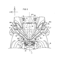
- FIG. 3 is an exploded perspective view of the headlight 36.
- FIG. 4 is a vertical cross-sectional view of the headlight 36 taken on line IV-IV of FIG. 2 .
- FIG. 5 is a plan view of the headlight 36.
- FIG. 6 is a front view of the headlight 36.
- the headlight 36 includes a headlight body 38 and a headlight cover 40.
- the headlight body 38 includes a projector lamp unit 42, a reflector lamp unit 44 and a support member 45.
- the projector lamp unit 42 and reflector lamp unit 44 are selectively turned on. Light emitted by the projector lamp unit 42 is used as a low beam. Light emitted by the reflector lamp unit 44 is used as a high beam.
- the projector lamp unit 42 includes an illuminator 46 and a lens (inner lens) 48.
- the illuminator 46 may be a halogen lamp, for example.
- the illuminator 46 is located at the rearmost point of the projector lamp unit 42.
- the lens 48 is made from glass.
- the front side of the lens 48 is a curved hemispherical surface convex toward the front.
- the rear side of the lens 48 is a flat surface expanding upward and downward and to the left and right.
- the lens 48 is located at the front of the projector lamp unit 42.
- the lens 48 passes light from the illuminator 48.
- the reflector lamp unit 44 includes an illuminator 50 and a reflector 52.
- the illuminator 50 may be a halogen lamp, for example.
- the illuminator 50 is located at the rear of the reflector lamp unit 44.
- the reflector 52 includes a concave portion 521 that is open toward the front.
- the illuminator 50 is located inside the concave portion 521.
- the reflector 52 reflects light emitted by the illuminator 50 toward the front.
- the support member 45 supports the projector lamp unit 42 and reflector lamp unit 44.
- the projector lamp unit 42 is located lower than the reflector lamp unit 44.
- the rearmost point of the projector lamp unit 42 is located forward of the rearmost point of the reflector lamp unit 44.
- the illuminator 46 included in the projector lamp unit 42 and the illuminator 50 included in the reflector lamp unit 44 are vertically arranged, overlapping the head pipe 14.
- the length of the projector lamp unit 42 as measured in a front-to-rear direction is greater than the length of the reflector lamp unit 44 as measured in a front-to-rear direction.
- the foremost point of the projector lamp unit 42 is the center of the front side of the lens 48.
- the rearmost point of the projector lamp unit 42 is the rearmost point of the illuminator 46.
- the foremost point of the reflector lamp unit 44 is the opening edge of the concave portion 521 of the reflector 52.
- the rearmost point of the reflector lamp unit 44 is the rearmost point of the illuminator 50.
- the foremost point of the projector lamp unit 42 is located forward of the foremost point of the reflector lamp unit 44. This allows the headlight cover 40 to have a front side that slopes downward toward the front. As a result, air resistance of the headlight 36 may be reduced.
- the headlight body 38 further includes a left illuminator 53 and right illuminator 54.
- the left illuminator 53 and right illuminator 54 are attached to the support member 45.
- the left illuminator 53 and right illuminator 54 may serve as position lights or flashers, for example.
- the left illuminator 53 and right illuminator 54 are located to the left and right, respectively, of the direct line L1 connecting the illuminator 46 of the projector lamp unit 42 with the illuminator 50 of the reflector lamp unit 44.
- the illuminator 46 of the projector lamp unit 42 and the illuminator 50 of the reflector lamp unit 44 is located above and below, respectively, the direct line L2 connecting the left illuminator 53 with the right illuminator 54.
- the lowermost point of the illuminator 46 of the projector lamp unit 42 is located lower than the lowermost point of each of the left illuminator 53 and right illuminator 54.
- the left illuminator 53 is located to the left of the left front fork tube 22, while the right illuminator 54 is located to the right of the right front fork tube 22.
- the headlight cover 40 includes a cover lens (outer lens) 56 made from a colorless and transparent synthetic resin.
- the cover lens 56 includes a center lens 56C, a left lens 56L and a right lens 56R.
- the cover lens 56 is located forward of the lens 48.
- the center lens 56C is located forward of both the illuminator 46 of the projector lamp unit 42 and the illuminator 50 of the reflector lamp unit 44.
- the center lens 56C passes light emitted by the illuminator 46 and illuminator 50.
- the center lens 56C is larger than each of the left lens 56L and the right lens 56R.
- the rear edge 56Cr of the center lens 56C is located higher than the foremost point 56Cf.
- a rear portion of the center lens 56C has a greater width in a left-to-right direction of the vehicle than a front portion of the center lens 56C.
- the rear edge 56Cr of the center lens 56C means the edge of the center lens 56C that is located rearward.
- the left lens 56L is located forward of the left illuminator 53.
- the left lens 56L passes light emitted by the left illuminator 53.
- the rearmost point 56Lr of the left lens 56L is located higher than the foremost point 56Lf of the lens.
- the foremost point 56Lf of the left lens 56L is the foremost of the lens as viewed from above the cover lens 56, as shown in FIG. 5 .
- the left lens 56L is formed integrally with the center lens 56C.
- the foremost point and surrounding portions of the left lens 56L are connected with the center lens 56C in the vicinity of the foremost point of the center lens 56C.
- the foremost point 56Lf of the left lens 56L is located rearward of the foremost point 56Cf of the center lens 56C.
- the foremost point 56Lf of the left lens 56L is located to the right of the left front fork tube 22.
- the rearmost point 56Lr of the left lens 56L is located rearward of the rear edge 56Cr of the center lens 56C. As shown in FIGS. 5 and 6 , the rearmost point 56Lr of the left lens 56L is farther from the center lens 56C than the foremost point 56Lf of the left lens 56L is in a left-to-right direction of the vehicle. As shown in FIG. 6 , the rearmost point 56Lr of the left lens 56L is located to the left of the left front fork tube 22.
- the right lens 56R is located forward of the right illuminator 54.
- the right lens 56R passes light emitted by the right illuminator 54.
- the rearmost point 56Rr of the right lens 56R is located higher than the foremost point 56Rf of the lens.
- the foremost point 56Rf of the right lens 56R is the foremost of the lens as viewed from above the cover lens 56, as shown in FIG. 5 .
- the right lens 56R is formed integrally with the center lens 56C.
- the foremost point and surrounding portions of the right lens 56R is connected with the center lens 56C in the vicinity of the foremost point of the center lens 56C.
- the foremost point 56Rf of the right lens 56R is located rearward of the foremost point 56Cf of the center lens 56C. As shown in FIG. 6 , the foremost point 56Rf of the right lens 56R is located to the left of the right front fork tube 22.
- the rearmost point 56Rr of the right lens 56R is located rearward of the rear edge 56Cr of the center lens 56C. As shown in FIGS. 5 and 6 , the rearmost point 56Rr of the right lens 56R is farther from the center lens 56C than the foremost point 56Rf of the right lens 56R is in a left-to-right direction of the vehicle. As shown in FIG. 6 , the rearmost point 56Rr of the right lens 56R is located to the right of the right front fork tube 22.
- the headlight 36 is attached to the head pipe 14 by an attachment device 58.
- the attachment device 58 includes an upper connecting member 60 and a lower connecting member 62.
- the upper connecting member 60 is a metal stay.
- the upper connecting member 60 connects the headlight 36 with the head pipe 14.
- the upper connecting member 60 includes an attachment portion 64 and an extending portion 66.
- the attachment portion 64 may be shaped as a plate, for example.
- the attachment portion 64 is attached to an attachment piece 68 included in the headlight 36.
- the attachment piece 68 includes an extending portion 70 and a vertical wall 72.
- the extending portion 70 extends rearward from the rear portion of the headlight body 38.
- two extending portions 70 are formed on the upper edge of the headlight body 38.
- the vertical wall 72 is provided on the rear end of the extending portion 70.
- the vertical wall 72 connects the rear ends of two extending portions 70.
- the vertical wall 72 extends upward from the rear end of the extending portion 70.
- the vertical wall 72 extends in a direction substantially perpendicular to the direction in which the extending portion 70 extends.
- the right end of the vertical wall 72 is located within the vehicle to the right of the central axis L3 of the head pipe 14, while the left end of the vertical wall 72 is located within the vehicle to the left of the central axis L3 of the head pipe 14.
- the attachment portion 64 may be attached to the attachment piece 68 in the following manner. First, the attachment surface of the attachment portion 64 (i.e. the front surface of the attachment portion 64) is placed over the attachment surface of the attachment piece 68 (i.e. the rear surface of the vertical wall 72). Then, the attachment portion 64 is attached to the attachment piece 68 by a bolt and a nut, for example.
- the attachment portion 64 may have strengthening ribs on its lower edge. This will improve the strength of the attachment portion 64.
- the extending portion 66 is an elongated member.
- the extending portion 66 includes an upper extending portion 661, a lower extending portion 662 and a connecting portion 663.
- the upper extending portion 661 and lower connecting portion 662 extend in a front-to-rear direction.
- the connecting portion 663 extends in a top-to-bottom direction to connect the upper extending portion 661 with the lower connecting portion 662.
- the attachment portion 64 is provided on the front end of the extending portion 66.
- the front end of the extending portion 66 is connected with the right end of the attachment portion 64.
- the attachment portion 64 may be connected with the extending portion 66 by welding the extending portion 66 to the attachment portion 64, for example.
- the rear end of the extending portion 66 is attached to the head pipe 14.
- the extending portion 66 may be attached to the head pipe 14 by welding or bolting, for example.
- the extending portion 66 may have strengthening ribs on at least one of its upper edge and its lower edge. This will improve the strength of the extending portion 66.
- the lower connecting member 62 is a metal stay.
- the lower connecting member 62 connects the headlight 36 with the head pipe 14.
- the lower connecting member 62 includes an extending portion 74, a first attachment portion 76 and a second attachment portion 78.
- the extending portion 74 is an elongated member.
- the extending portion 74 may be, for example, a rod or pipe, or may be a plate.
- the first attachment portion 76 is provided on the front end of the extending portion 74.
- the first attachment portion 76 may be fixed to the extending portion 74 by welding, for example.
- the first attachment portion 76 is formed by fixing the front end of the extending portion 74 to the rear portion of the headlight body 38.
- the first attachment portion 76 may be fixed to the headlight body 38 by bolting, for example.
- the first attachment portion 76 is fixed to the headlight by fixing the front end of the extending portion 74 to a mount 77 included in the support member 45.
- the mount 77 is located higher than the rear bottom edge 451 of the support member 45 and in the vicinity of the rear bottom edge 451.
- the rear bottom edge 451 is the rear edge of the lower surface 452 of the support member 45.
- the mount 77 is provided on an attachment surface 453 of the support member 45. As shown in FIG.
- the mount 77 is located in the vehicle to the left of the central axis L3 of the head pipe 14. As shown in FIG. 5 , the mount 77 is located forward of the vertical wall 72.
- the attachment surface 453 is a lower portion of the rear surface of the headlight 36.
- the second attachment portion 78 is provided on the rear end of the extending portion 74.
- the second attachment portion 78 may be fixed to the extending portion 74 by welding, for example.
- the second attachment portion 78 includes two fixing pieces 781 and 782. These fixing pieces 781 and 782 are used to fix the second attachment portion 78 to the rear end of the extending portion 74.
- the fixing piece 781 is fixed to the extending portion 74 at the rear end of the extending portion 74.
- the fixing piece 782 is fixed to the extending portion 74 and located closer to the front end of the portion than the fixing piece 781 is.
- the second attachment portion 78 is fixed to the extending portion 74 more firmly.
- the second attachment portion 78 is formed by fixing the rear end of the extending portion 74 to the head pipe 14.
- the second attachment portion 78 may be fixed to the head pipe 14 by welding or bolting, for example.
- the attachment device 58 i.e. the upper connecting member 60 and lower connecting member 62 are both located higher than the bracket 20. This will reduce the lengths of the upper connecting member 60 and lower connecting member 62 (i.e. their lengths in a front-to-rear direction of the vehicle). As a result, the strength of each member, i.e. the upper connecting member 60 and lower connecting member 62, will be improved. Further, the headlight 36 will be closer to the head pipe 14, thereby improving its resistance to vibrations while driving, for example. Accordingly, the headlight 36 may be attached to the head pipe 14 in a stable manner even if a large headlight 36 including four illuminators 46, 50, 53 and 54 as shown in FIGS. 3 to 6 is employed, for example. In other words, the headlight 36 may be supported in a stable manner.
- the headlight 36 includes a projector lamp unit 42.
- the projector lamp unit 42 includes a lens 48.
- the lens 48 is made of glass.
- the lens 48 is relatively heavy. Even with such a lens 48, the headlight 36 is supported in a stable manner.
- the bracket 20 when the upper connecting member 60 and lower connecting member 62 connect the headlight 36 with the head pipe 14, the bracket 20 is located lower than the lower connecting member 62, as shown in FIG. 4 .
- the rear bottom edge 451 of the headlight 36 is located forward of the bracket 20.
- the attachment surface 453 is located forward of the bracket 20.
- the mount 77 is located forward of the bracket 20. That is, the bracket 20 is not in contact with the headlight 36 or the lower connecting member 62.
- FIG. 4 shows the motorcycle where the steering shaft 16 is positioned in the middle of its rotational range.
- the handlebars 18 and thus the steering shaft 16
- the handlebars 18 may be fully turned to the right, as shown in FIG. 7 .
- the left end of the bracket 20 i.e. the portion thereof that supports the left front fork tube 22
- the left end of the bracket 20 will not be located in the vehicle to the right of the central axis L3 of the head pipe 14 even when the handlebars 18 are fully turned to the right.
- the bracket 20 When the handlebars 18 are fully turned to the right, the bracket 20 is located lower than the lower connecting member 62, as shown in FIG. 8 .
- the rear bottom edge 451 of the headlight 36 is located forward of the bracket 20.
- the attachment surface 453 is located forward of the bracket 20.
- the mount 77 is located forward of the bracket 20.
- bracket 20 will not be in contact with the headlight 36 and lower connecting member 62 even when the handlebars 18 are fully turned to the right.
- the handlebars 18 may be fully turned to the left, as shown in FIG. 9 .
- the right end of the bracket 20 i.e. the portion thereof that supports the right front fork tube 22
- the right end of the bracket 20 will not be located in the vehicle to the left of the central axis L3 of the head pipe 14 even when the handlebars 18 are fully turned to the left.
- the bracket 20 When the handlebars 18 are fully turned to the left, the bracket 20 is located lower than the lower connecting member 62, as shown in FIG. 10 .
- the rear bottom edge 451 of the headlight 36 is located forward of the bracket 20.
- the attachment surface 453 is located forward of the bracket 20.
- the mount 77 is located forward of the bracket 20.
- bracket 20 will not be in contact with the headlight 36 and lower connecting member 62 even when the headlight 36 is fully turned to the left.
- the attachment device 58 includes an upper connecting member 60 and lower connecting member 62.
- the upper connecting member 60 and the lower connecting member 62 are vertically separated from each other.
- the headlight 36 may be supported at two vertically separated locations. As a result, the headlight 36 may be supported in a more stable manner.
- the upper connecting member 60 is fixed to the head pipe 14 at a location that is closer to its upper end than the center C of the head pipe 14 in an axial direction is.
- the lower connecting member 62 is fixed to the head pipe 14 at a location that is closer to its lower end than the center C of the head pipe 14 in an axial direction is. This allows the location at which the upper connecting member 60 is fixed to the head pipe 14 to be vertically separated from the location at which the lower connecting member 62 is fixed to the head pipe 14. As a result, the headlight 36 may be supported in a yet more stable manner.
- the end of the upper connecting member 60 that is close to the headlight 36 is shifted in a left-to-right direction of the vehicle from the end of the lower connecting member 62 that is close to the headlight 36. This allows the headlight 36 to be supported in a still more stable manner.
- the end of the upper connecting member 60 that is close to the headlight 36 is shifted in a front-to-rear direction of the vehicle from the end of the lower connecting member 62 that is close to the headlight 36. This allows the headlight 36 to be supported in a yet more stable manner.
- the upper connecting member 60 and lower connecting member 62 are directly fixed to the head pipe 14.
- the upper connecting member 60 and lower connecting member 62 may be fixed to the head pipe 14 more firmly.
- the headlight 36 may be supported in a more stable manner.
- the illuminator 46 of the projector lamp unit 42 and the illuminator 50 of the reflector lamp unit 44 overlap the head pipe 14 as viewed from the front of the vehicle.
- the projector lamp unit 42 and reflector lamp unit 44 overlap the head pipe 14.
- the rearmost point of the illuminator 46 is located forward of the rearmost point of the illuminator 50.
- the left end of the bracket 20 is located in the vehicle to the left of the central axis L3 of the head pipe 14 when the handlebars 18 are fully turned to the right.
- the right end of the bracket 20 is located in the vehicle to the right of the central axis L3 of the head pipe 14 when the handlebars 18 are fully turned to the left.
- the projector lamp unit 42 and reflector lamp unit 44 are unlikely to contact the bracket 20.
- the projector lamp unit 42 and reflector lamp unit 44 can be easily brought close to the head pipe 14.
- the attachment surface 453 of the support member 45 is located forward of the bracket 20 when the handlebars 18 are fully turned to the right. Further, as shown in FIGS. 9 and 10 , the attachment surface 453 of the support member 45 is located forward of the bracket 20 when the handlebars 18 are fully turned to the left. This prevents the bracket 20 from contacting the headlight 36.
- the projector lamp unit 42 and reflector lamp unit 44 are vertically arranged, resulting in a long dimension of the headlight 36 in a top-to-bottom direction. This makes it difficult to allow the headlight 36 to be brought upward of the bracket 20.
- the attachment surface 453 of the support member 45 is located forward of the bracket 20. This prevents the bracket 20 from contacting the headlight 36.
- the attachment surface 453 of the support member 45 is located forward of the bracket 20. As such, it is important to ensure a sufficient strength of the attachment device 58.
- the attachment device 58 includes an upper connecting member 60 and lower connecting member 62. This facilitates ensuring a sufficient strength of the attachment device 58. This allows the headlight 36 to be supported in a stable manner.
- the projector lamp unit 42 includes a lens 48 made of glass.
- the projector lamp unit 42 is heavier than the reflector lamp unit 44.
- the projector lamp unit 42 is located lower than the reflector lamp unit 44. As a result, the headlight 36 may be easily supported in a stable manner.
- a member made of resin may be present between at least one of the upper connecting member 60 and lower connecting member 62 and the headlight 36.
- the present invention is not limited thereto and may be used in a three- or four-wheeled leaning vehicle.
Landscapes
- Engineering & Computer Science (AREA)
- Mechanical Engineering (AREA)
- Lighting Device Outwards From Vehicle And Optical Signal (AREA)
- Non-Portable Lighting Devices Or Systems Thereof (AREA)
Abstract
Description
- The present invention relates to a structure for attaching a headlight in a straddle type vehicle.
- Straddle type vehicles include motorcycles, for example. A motorcycle includes a headlight. A headlight is disclosed, for example, in
JP 3020964 B Sho58(1983)-184346 - In each of Patent Documents 1 and 2, a motorcycle includes a pair of front fork tubes. The front fork tubes are connected with each other by upper and lower brackets. A headlight is located between the two brackets and forward of the front fork tubes.
- An object of the present invention is to provide a straddle type vehicle where a larger headlight may be attached to a body frame in a stable manner.
- This object is achieved by a straddle type vehicle according to claim 1.
- It has been found out that, while some motorcycles may include a larger headlight, for example, to differentiate them from other motorcycles, such a larger headlight may lead to difficulties in supporting its weight.
- A straddle type vehicle of the present invention includes: a front wheel; a pair of front wheel support members supporting the front wheel; a bracket supporting an upper end of each of the front wheel support members; a steering shaft extending upward from the bracket; a handlebar connected to the steering shaft; a body frame including a head pipe rotatably supporting the steering shaft; a headlight located forward of the head pipe; and an attachment device configured to attach the headlight to the body frame, wherein the headlight includes: an illuminator; and a lens made of glass configured to pass light from the illuminator, and the attachment device and the headlight are positioned so as not to get in contact with the bracket.
- In a straddle type vehicle of the present invention, a larger headlight may be attached to a body frame in a stable manner.
-
-
FIG. 1 is a left side view of an entire motorcycle according to an embodiment of the present invention. -
FIG. 2 is a front view of the motorcycle ofFIG. 1 . -
FIG. 3 is an exploded perspective view of the headlight. -
FIG. 4 is a vertical cross-sectional view of the headlight. -
FIG. 5 is a plan view of the headlight. -
FIG. 6 is a front view of the headlight. -
FIG. 7 is a plan view of a cross section illustrating the relationship between the headlight and bracket positioned when the handlebars are fully turned to the right. -
FIG. 8 is a side view of a cross section illustrating the relationship between the headlight and bracket positioned when the handlebars are fully turned to the right. -
FIG. 9 is a plan view of a cross section illustrating the relationship between the headlight and bracket positioned when the handlebars are fully turned to the left. -
FIG. 10 is a side view of a cross section illustrating the relationship between the headlight and bracket positioned when the handlebars are fully turned to the left. - A straddle type vehicle according to an embodiment of the present invention will now be described with reference to the drawings. The present embodiment illustrates a scooter-type motorcycle as an example of a straddle type vehicle. The same or corresponding elements in different drawings are labeled with the same numerals, and their description will not be repeated.
-
FIG. 1 is a left side view of amotorcycle 10 of an embodiment of the present invention.FIG. 2 is a front view of themotorcycle 10. - In the following description, "front/forward", "behind/rear(ward)", "left" and "right" each denote a direction as perceived by a rider sitting on the
seat 30 of themotorcycle 10. InFIG. 1 , the arrow F indicates the forward direction with respect to themotorcycle 10, while the arrow U indicates the upward direction with respect to themotorcycle 10. InFIG. 2 , the arrow R indicates the right direction with respect to themotorcycle 10, while the arrow U indicates the upward direction with respect to themotorcycle 10. - The
motorcycle 10 includes abody frame 12. Ahead pipe 14 is provided on the front end of thebody frame 12. - A
steering shaft 16 is inserted into thehead pipe 14, the steering shaft being rotatable to the left and right.Handlebars 18 are attached to the top end of thesteering shaft 16. Thehandlebars 18 may be operated to rotate thesteering shaft 16. - A
bracket 20 is attached to the bottom end of thesteering shaft 16. The top end of each of a pair of front fork tubes 22 (front wheel support members) is attached to thebracket 20. Thefront fork tubes 22 rotatably support thefront wheel 24. - A
front fender 26 is located above thefront wheel 24. Thefront fork tubes 22 support thefront fender 26. - The
body frame 12 is covered with abody cover 28. Thebody cover 28 may be made from a synthetic resin, for example. - A
seat 30 is located above a rear portion of thebody frame 12. A storage space is formed below theseat 30. A helmet, for example, may be stored in the storage space. - A
power unit 32 is located below a rear portion of thebody frame 12. Thebody frame 12 supports thepower unit 32, the power unit being swingable in a top-to-bottom direction. - A
rear wheel 34 is rotatably attached to the rear end of thepower unit 32. Power from thepower unit 32 may be transmitted to therear wheel 34 to cause therear wheel 34 to rotate. - The
motorcycle 10 includes aheadlight 36. As shown inFIGS. 1 and2 , theheadlight 36 is located above thefront fender 26 and forward of thehead pipe 14. - The
headlight 36 will be described with reference toFIGS. 3 to 6 .FIG. 3 is an exploded perspective view of theheadlight 36.FIG. 4 is a vertical cross-sectional view of theheadlight 36 taken on line IV-IV ofFIG. 2 .FIG. 5 is a plan view of theheadlight 36.FIG. 6 is a front view of theheadlight 36. - As shown in
FIGS. 3 to 5 , theheadlight 36 includes aheadlight body 38 and aheadlight cover 40. - As shown in
FIGS. 3 and4 , theheadlight body 38 includes aprojector lamp unit 42, areflector lamp unit 44 and asupport member 45. - According to the present embodiment, the
projector lamp unit 42 andreflector lamp unit 44 are selectively turned on. Light emitted by theprojector lamp unit 42 is used as a low beam. Light emitted by thereflector lamp unit 44 is used as a high beam. - As shown in
FIGS. 3 and4 , theprojector lamp unit 42 includes anilluminator 46 and a lens (inner lens) 48. - The
illuminator 46 may be a halogen lamp, for example. Theilluminator 46 is located at the rearmost point of theprojector lamp unit 42. - The
lens 48 is made from glass. The front side of thelens 48 is a curved hemispherical surface convex toward the front. The rear side of thelens 48 is a flat surface expanding upward and downward and to the left and right. Thelens 48 is located at the front of theprojector lamp unit 42. Thelens 48 passes light from theilluminator 48. - As shown in
FIGS. 3 and4 , thereflector lamp unit 44 includes anilluminator 50 and areflector 52. - The
illuminator 50 may be a halogen lamp, for example. Theilluminator 50 is located at the rear of thereflector lamp unit 44. - The
reflector 52 includes aconcave portion 521 that is open toward the front. Theilluminator 50 is located inside theconcave portion 521. Thereflector 52 reflects light emitted by theilluminator 50 toward the front. - As shown in
FIG. 4 , thesupport member 45 supports theprojector lamp unit 42 andreflector lamp unit 44. As shown inFIGS. 3 and4 , theprojector lamp unit 42 is located lower than thereflector lamp unit 44. As shown inFIG. 4 , the rearmost point of theprojector lamp unit 42 is located forward of the rearmost point of thereflector lamp unit 44. - As viewed from the front of the vehicle, as shown in
FIG. 6 , theilluminator 46 included in theprojector lamp unit 42 and theilluminator 50 included in thereflector lamp unit 44 are vertically arranged, overlapping thehead pipe 14. - The length of the
projector lamp unit 42 as measured in a front-to-rear direction is greater than the length of thereflector lamp unit 44 as measured in a front-to-rear direction. The foremost point of theprojector lamp unit 42 is the center of the front side of thelens 48. The rearmost point of theprojector lamp unit 42 is the rearmost point of theilluminator 46. The foremost point of thereflector lamp unit 44 is the opening edge of theconcave portion 521 of thereflector 52. The rearmost point of thereflector lamp unit 44 is the rearmost point of theilluminator 50. - As shown in
FIG. 4 , the foremost point of theprojector lamp unit 42 is located forward of the foremost point of thereflector lamp unit 44. This allows theheadlight cover 40 to have a front side that slopes downward toward the front. As a result, air resistance of theheadlight 36 may be reduced. - As shown in
FIGS. 3 and6 , theheadlight body 38 further includes aleft illuminator 53 andright illuminator 54. Theleft illuminator 53 andright illuminator 54 are attached to thesupport member 45. Theleft illuminator 53 andright illuminator 54 may serve as position lights or flashers, for example. - As shown in
FIG. 6 , as viewed from the front of the vehicle, theleft illuminator 53 andright illuminator 54 are located to the left and right, respectively, of the direct line L1 connecting theilluminator 46 of theprojector lamp unit 42 with theilluminator 50 of thereflector lamp unit 44. Theilluminator 46 of theprojector lamp unit 42 and theilluminator 50 of thereflector lamp unit 44 is located above and below, respectively, the direct line L2 connecting theleft illuminator 53 with theright illuminator 54. The lowermost point of theilluminator 46 of theprojector lamp unit 42 is located lower than the lowermost point of each of theleft illuminator 53 andright illuminator 54. - As shown in
FIGS. 2 and6 , as viewed from the front of the vehicle, theleft illuminator 53 is located to the left of the leftfront fork tube 22, while theright illuminator 54 is located to the right of the rightfront fork tube 22. - As shown in
FIGS. 3 to 6 , theheadlight cover 40 includes a cover lens (outer lens) 56 made from a colorless and transparent synthetic resin. Thecover lens 56 includes acenter lens 56C, aleft lens 56L and aright lens 56R. Thecover lens 56 is located forward of thelens 48. - As shown in
FIG. 6 , thecenter lens 56C is located forward of both theilluminator 46 of theprojector lamp unit 42 and theilluminator 50 of thereflector lamp unit 44. Thecenter lens 56C passes light emitted by theilluminator 46 andilluminator 50. As shown inFIG. 6 , as viewed from the front of the vehicle, thecenter lens 56C is larger than each of theleft lens 56L and theright lens 56R. - As shown in
FIGS. 3 ,4 and6 , the rear edge 56Cr of thecenter lens 56C is located higher than the foremost point 56Cf. A rear portion of thecenter lens 56C has a greater width in a left-to-right direction of the vehicle than a front portion of thecenter lens 56C. In the present embodiment, the rear edge 56Cr of thecenter lens 56C means the edge of thecenter lens 56C that is located rearward. - As shown in
FIG. 6 , theleft lens 56L is located forward of theleft illuminator 53. Theleft lens 56L passes light emitted by theleft illuminator 53. As shown inFIGS. 3 and6 , the rearmost point 56Lr of theleft lens 56L is located higher than the foremost point 56Lf of the lens. In the present embodiment, the foremost point 56Lf of theleft lens 56L is the foremost of the lens as viewed from above thecover lens 56, as shown inFIG. 5 . - As shown in
FIGS. 3 ,5 and6 , theleft lens 56L is formed integrally with thecenter lens 56C. In the present embodiment, the foremost point and surrounding portions of theleft lens 56L are connected with thecenter lens 56C in the vicinity of the foremost point of thecenter lens 56C. - As shown in
FIG. 5 , the foremost point 56Lf of theleft lens 56L is located rearward of the foremost point 56Cf of thecenter lens 56C. As shown inFIG. 6 , the foremost point 56Lf of theleft lens 56L is located to the right of the leftfront fork tube 22. - As shown in
FIG. 5 , the rearmost point 56Lr of theleft lens 56L is located rearward of the rear edge 56Cr of thecenter lens 56C. As shown inFIGS. 5 and6 , the rearmost point 56Lr of theleft lens 56L is farther from thecenter lens 56C than the foremost point 56Lf of theleft lens 56L is in a left-to-right direction of the vehicle. As shown inFIG. 6 , the rearmost point 56Lr of theleft lens 56L is located to the left of the leftfront fork tube 22. - As shown in
FIG. 6 , theright lens 56R is located forward of theright illuminator 54. Theright lens 56R passes light emitted by theright illuminator 54. As shown inFIGS. 3 and6 , the rearmost point 56Rr of theright lens 56R is located higher than the foremost point 56Rf of the lens. In the present embodiment, the foremost point 56Rf of theright lens 56R is the foremost of the lens as viewed from above thecover lens 56, as shown inFIG. 5 . - As shown in
FIGS. 3 ,5 and6 , theright lens 56R is formed integrally with thecenter lens 56C. In the present embodiment, the foremost point and surrounding portions of theright lens 56R is connected with thecenter lens 56C in the vicinity of the foremost point of thecenter lens 56C. - As shown in
FIG. 5 , the foremost point 56Rf of theright lens 56R is located rearward of the foremost point 56Cf of thecenter lens 56C. As shown inFIG. 6 , the foremost point 56Rf of theright lens 56R is located to the left of the rightfront fork tube 22. - As shown in
FIG. 5 , the rearmost point 56Rr of theright lens 56R is located rearward of the rear edge 56Cr of thecenter lens 56C. As shown inFIGS. 5 and6 , the rearmost point 56Rr of theright lens 56R is farther from thecenter lens 56C than the foremost point 56Rf of theright lens 56R is in a left-to-right direction of the vehicle. As shown inFIG. 6 , the rearmost point 56Rr of theright lens 56R is located to the right of the rightfront fork tube 22. - The
headlight 36 is attached to thehead pipe 14 by anattachment device 58. Theattachment device 58 includes an upper connectingmember 60 and a lower connectingmember 62. - The upper connecting
member 60 is a metal stay. The upper connectingmember 60 connects theheadlight 36 with thehead pipe 14. The upper connectingmember 60 includes anattachment portion 64 and an extendingportion 66. - The
attachment portion 64 may be shaped as a plate, for example. Theattachment portion 64 is attached to anattachment piece 68 included in theheadlight 36. - As shown in
FIGS. 3 to 5 , theattachment piece 68 includes an extendingportion 70 and avertical wall 72. - The extending
portion 70 extends rearward from the rear portion of theheadlight body 38. In the implementation shown inFIGS. 3 to 5 , two extendingportions 70 are formed on the upper edge of theheadlight body 38. - The
vertical wall 72 is provided on the rear end of the extendingportion 70. In the implementation shown inFIGS. 3 to 5 , thevertical wall 72 connects the rear ends of two extendingportions 70. Thevertical wall 72 extends upward from the rear end of the extendingportion 70. In other words, thevertical wall 72 extends in a direction substantially perpendicular to the direction in which the extendingportion 70 extends. As shown inFIG. 5 , the right end of thevertical wall 72 is located within the vehicle to the right of the central axis L3 of thehead pipe 14, while the left end of thevertical wall 72 is located within the vehicle to the left of the central axis L3 of thehead pipe 14. - For example, the
attachment portion 64 may be attached to theattachment piece 68 in the following manner. First, the attachment surface of the attachment portion 64 (i.e. the front surface of the attachment portion 64) is placed over the attachment surface of the attachment piece 68 (i.e. the rear surface of the vertical wall 72). Then, theattachment portion 64 is attached to theattachment piece 68 by a bolt and a nut, for example. - The
attachment portion 64 may have strengthening ribs on its lower edge. This will improve the strength of theattachment portion 64. - The extending
portion 66 is an elongated member. In the implementation shown inFIGS. 4 and5 , the extendingportion 66 includes an upper extendingportion 661, a lower extendingportion 662 and a connectingportion 663. The upper extendingportion 661 and lower connectingportion 662 extend in a front-to-rear direction. The connectingportion 663 extends in a top-to-bottom direction to connect the upper extendingportion 661 with the lower connectingportion 662. - The
attachment portion 64 is provided on the front end of the extendingportion 66. In the present embodiment, the front end of the extendingportion 66 is connected with the right end of theattachment portion 64. Theattachment portion 64 may be connected with the extendingportion 66 by welding the extendingportion 66 to theattachment portion 64, for example. - The rear end of the extending
portion 66 is attached to thehead pipe 14. The extendingportion 66 may be attached to thehead pipe 14 by welding or bolting, for example. - The extending
portion 66 may have strengthening ribs on at least one of its upper edge and its lower edge. This will improve the strength of the extendingportion 66. - The lower connecting
member 62 is a metal stay. The lower connectingmember 62 connects theheadlight 36 with thehead pipe 14. The lower connectingmember 62 includes an extendingportion 74, afirst attachment portion 76 and asecond attachment portion 78. - The extending
portion 74 is an elongated member. The extendingportion 74 may be, for example, a rod or pipe, or may be a plate. - The
first attachment portion 76 is provided on the front end of the extendingportion 74. Thefirst attachment portion 76 may be fixed to the extendingportion 74 by welding, for example. - The
first attachment portion 76 is formed by fixing the front end of the extendingportion 74 to the rear portion of theheadlight body 38. Thefirst attachment portion 76 may be fixed to theheadlight body 38 by bolting, for example. In the present embodiment, thefirst attachment portion 76 is fixed to the headlight by fixing the front end of the extendingportion 74 to amount 77 included in thesupport member 45. Themount 77 is located higher than therear bottom edge 451 of thesupport member 45 and in the vicinity of therear bottom edge 451. Therear bottom edge 451 is the rear edge of thelower surface 452 of thesupport member 45. Themount 77 is provided on anattachment surface 453 of thesupport member 45. As shown inFIG. 5 , themount 77 is located in the vehicle to the left of the central axis L3 of thehead pipe 14. As shown inFIG. 5 , themount 77 is located forward of thevertical wall 72. Theattachment surface 453, together with thelower surface 452, defines therear bottom edge 451. In the present embodiment, theattachment surface 453 is a lower portion of the rear surface of theheadlight 36. - The
second attachment portion 78 is provided on the rear end of the extendingportion 74. Thesecond attachment portion 78 may be fixed to the extendingportion 74 by welding, for example. In the implementation shown inFIGS. 4 and5 , thesecond attachment portion 78 includes two fixingpieces pieces second attachment portion 78 to the rear end of the extendingportion 74. The fixingpiece 781 is fixed to the extendingportion 74 at the rear end of the extendingportion 74. The fixingpiece 782 is fixed to the extendingportion 74 and located closer to the front end of the portion than the fixingpiece 781 is. Thus, thesecond attachment portion 78 is fixed to the extendingportion 74 more firmly. - The
second attachment portion 78 is formed by fixing the rear end of the extendingportion 74 to thehead pipe 14. Thesecond attachment portion 78 may be fixed to thehead pipe 14 by welding or bolting, for example. - As shown in
FIG. 4 , in the present embodiment, theattachment device 58, i.e. the upper connectingmember 60 and lower connectingmember 62 are both located higher than thebracket 20. This will reduce the lengths of the upper connectingmember 60 and lower connecting member 62 (i.e. their lengths in a front-to-rear direction of the vehicle). As a result, the strength of each member, i.e. the upper connectingmember 60 and lower connectingmember 62, will be improved. Further, theheadlight 36 will be closer to thehead pipe 14, thereby improving its resistance to vibrations while driving, for example. Accordingly, theheadlight 36 may be attached to thehead pipe 14 in a stable manner even if alarge headlight 36 including fourilluminators FIGS. 3 to 6 is employed, for example. In other words, theheadlight 36 may be supported in a stable manner. - Particularly, in the present embodiment, the
headlight 36 includes aprojector lamp unit 42. Theprojector lamp unit 42 includes alens 48. Thelens 48 is made of glass. Thus, thelens 48 is relatively heavy. Even with such alens 48, theheadlight 36 is supported in a stable manner. - In the present embodiment, when the upper connecting
member 60 and lower connectingmember 62 connect theheadlight 36 with thehead pipe 14, thebracket 20 is located lower than the lower connectingmember 62, as shown inFIG. 4 . Therear bottom edge 451 of theheadlight 36 is located forward of thebracket 20. Theattachment surface 453 is located forward of thebracket 20. Themount 77 is located forward of thebracket 20. That is, thebracket 20 is not in contact with theheadlight 36 or the lower connectingmember 62. -
FIG. 4 shows the motorcycle where the steeringshaft 16 is positioned in the middle of its rotational range. Starting from this state, the handlebars 18 (and thus the steering shaft 16) may be fully turned to the right, as shown inFIG. 7 . In this state, the left end of the bracket 20 (i.e. the portion thereof that supports the left front fork tube 22) is located in the vehicle to the left of the central axis L3 of thehead pipe 14. In other words, the left end of thebracket 20 will not be located in the vehicle to the right of the central axis L3 of thehead pipe 14 even when thehandlebars 18 are fully turned to the right. - When the
handlebars 18 are fully turned to the right, thebracket 20 is located lower than the lower connectingmember 62, as shown inFIG. 8 . Therear bottom edge 451 of theheadlight 36 is located forward of thebracket 20. Theattachment surface 453 is located forward of thebracket 20. Themount 77 is located forward of thebracket 20. - That is, the
bracket 20 will not be in contact with theheadlight 36 and lower connectingmember 62 even when thehandlebars 18 are fully turned to the right. - Starting from the state shown in
FIG. 4 , thehandlebars 18 may be fully turned to the left, as shown inFIG. 9 . In this state, the right end of the bracket 20 (i.e. the portion thereof that supports the right front fork tube 22) is located in the vehicle to the right of the central axis L3 of thehead pipe 14. In other words, the right end of thebracket 20 will not be located in the vehicle to the left of the central axis L3 of thehead pipe 14 even when thehandlebars 18 are fully turned to the left. - When the
handlebars 18 are fully turned to the left, thebracket 20 is located lower than the lower connectingmember 62, as shown inFIG. 10 . Therear bottom edge 451 of theheadlight 36 is located forward of thebracket 20. Theattachment surface 453 is located forward of thebracket 20. Themount 77 is located forward of thebracket 20. - That is, the
bracket 20 will not be in contact with theheadlight 36 and lower connectingmember 62 even when theheadlight 36 is fully turned to the left. - In the present embodiment, the
attachment device 58 includes an upper connectingmember 60 and lower connectingmember 62. The upper connectingmember 60 and the lower connectingmember 62 are vertically separated from each other. Thus, theheadlight 36 may be supported at two vertically separated locations. As a result, theheadlight 36 may be supported in a more stable manner. - As shown in
FIG. 4 , in the present embodiment, the upper connectingmember 60 is fixed to thehead pipe 14 at a location that is closer to its upper end than the center C of thehead pipe 14 in an axial direction is. The lower connectingmember 62 is fixed to thehead pipe 14 at a location that is closer to its lower end than the center C of thehead pipe 14 in an axial direction is. This allows the location at which the upper connectingmember 60 is fixed to thehead pipe 14 to be vertically separated from the location at which the lower connectingmember 62 is fixed to thehead pipe 14. As a result, theheadlight 36 may be supported in a yet more stable manner. - As shown in
FIG. 5 , in the present embodiment, the end of the upper connectingmember 60 that is close to theheadlight 36 is shifted in a left-to-right direction of the vehicle from the end of the lower connectingmember 62 that is close to theheadlight 36. This allows theheadlight 36 to be supported in a still more stable manner. - As shown in
FIG. 5 , in the present embodiment, the end of the upper connectingmember 60 that is close to theheadlight 36 is shifted in a front-to-rear direction of the vehicle from the end of the lower connectingmember 62 that is close to theheadlight 36. This allows theheadlight 36 to be supported in a yet more stable manner. - In the present embodiment, the upper connecting
member 60 and lower connectingmember 62 are directly fixed to thehead pipe 14. Thus, the upper connectingmember 60 and lower connectingmember 62 may be fixed to thehead pipe 14 more firmly. As a result, theheadlight 36 may be supported in a more stable manner. - As shown in
FIGS. 2 and4 , in the present embodiment, theilluminator 46 of theprojector lamp unit 42 and theilluminator 50 of thereflector lamp unit 44 overlap thehead pipe 14 as viewed from the front of the vehicle. In other words, as viewed from the front of the vehicle, theprojector lamp unit 42 andreflector lamp unit 44 overlap thehead pipe 14. - Particularly, in the present embodiment, the rearmost point of the
illuminator 46 is located forward of the rearmost point of theilluminator 50. - In addition, as shown in
FIGS. 7 and8 , in the present embodiment, the left end of thebracket 20 is located in the vehicle to the left of the central axis L3 of thehead pipe 14 when thehandlebars 18 are fully turned to the right. Further, as shown inFIGS. 9 and10 , the right end of thebracket 20 is located in the vehicle to the right of the central axis L3 of thehead pipe 14 when thehandlebars 18 are fully turned to the left. - Even when the
bracket 20 is rotated, theprojector lamp unit 42 andreflector lamp unit 44 are unlikely to contact thebracket 20. Theprojector lamp unit 42 andreflector lamp unit 44 can be easily brought close to thehead pipe 14. - As shown in
FIGS. 7 and8 , in the present embodiment, theattachment surface 453 of thesupport member 45 is located forward of thebracket 20 when thehandlebars 18 are fully turned to the right. Further, as shown inFIGS. 9 and10 , theattachment surface 453 of thesupport member 45 is located forward of thebracket 20 when thehandlebars 18 are fully turned to the left. This prevents thebracket 20 from contacting theheadlight 36. - In the present embodiment, the
projector lamp unit 42 andreflector lamp unit 44 are vertically arranged, resulting in a long dimension of theheadlight 36 in a top-to-bottom direction. This makes it difficult to allow theheadlight 36 to be brought upward of thebracket 20. However, as described above, in the present embodiment, theattachment surface 453 of thesupport member 45 is located forward of thebracket 20. This prevents thebracket 20 from contacting theheadlight 36. - As described above, in the present embodiment, the
attachment surface 453 of thesupport member 45 is located forward of thebracket 20. As such, it is important to ensure a sufficient strength of theattachment device 58. In the present embodiment, theattachment device 58 includes an upper connectingmember 60 and lower connectingmember 62. This facilitates ensuring a sufficient strength of theattachment device 58. This allows theheadlight 36 to be supported in a stable manner. - In the present embodiment, the
projector lamp unit 42 includes alens 48 made of glass. Thus, theprojector lamp unit 42 is heavier than thereflector lamp unit 44. In themotorcycle 10, theprojector lamp unit 42 is located lower than thereflector lamp unit 44. As a result, theheadlight 36 may be easily supported in a stable manner. - In the above embodiment, a member made of resin, for example, may be present between at least one of the upper connecting
member 60 and lower connectingmember 62 and theheadlight 36. - While the above embodiment has illustrated a two-wheeled motorcycle, the present invention is not limited thereto and may be used in a three- or four-wheeled leaning vehicle.
- While an embodiment of the present invention has been described, the embodiment described above is merely an example that can be used to carry out the present invention. Thus, the present invention is not limited to the above embodiment and may be carried out where the above embodiment is modified as necessary without departing from the spirit of the invention.
Claims (12)
- A straddle type vehicle comprising:a front wheel (24);a pair of front wheel support members (22) supporting the front wheel (24);a bracket (20) supporting an upper end of each of the front wheel support members (22);a steering shaft (16) extending upward from the bracket (20);a handlebar (18) connected to the steering shaft (16);a body frame (12) including a head pipe (14) rotatably supporting the steering shaft (16);a headlight (36) located forward of the head pipe (14); andan attachment device (58) configured to attach the headlight (36) to the body frame (12),wherein the headlight (36) includes:an illuminator (46);an inner lens (48) made of glass configured to pass light from the illuminator (46); andan outer lens (56) made of a synthetic resin positioned to pass light from the illuminator (46) that has passed through the inner lens (48), andthe attachment device (58) and the headlight (36) are positioned so as not to get in contact with the bracket (20).
- The straddle type vehicle according to claim 1, wherein:the attachment device (58) includes a connecting member configured to connect the headlight (36) with the body frame (12),the connecting member including upper and lower connecting members (60, 62) with ends close to the headlight (36) separated vertically from each other.
- The straddle type vehicle according to claim 2, wherein:an end of the upper connecting member (60) that is close to the headlight (36) and an end of the lower connecting member (62) that is close to the headlight (36) are separated from each other in a left-to-right direction.
- The straddle type vehicle according to claim 2 or 3, wherein:an end of the upper connecting member (60) that is close to the headlight (36) and an end of the lower connecting member (62) that is close to the headlight (36) are separated from each other in a front-to-rear direction.
- The straddle type vehicle according to any one of claim 2 to 4, wherein:each of the upper and lower connecting members (60, 62) includes a metal stay.
- The straddle type vehicle according to claim 5, wherein:the stay is directly fixed to the body frame (12).
- The straddle type vehicle according to any one of claims 2 to 6, wherein:an end of the upper connecting member (60) close to the body frame (12) is located closer to an upper end of the head pipe (14) than a center of the head pipe (14) in an axial direction is, and an end of the lower connecting member (62) close to the body frame (12) is located closer to a lower end of the head pipe (14) than a center of the head pipe (14) in an axial direction is.
- The straddle type vehicle according to any one of claims 1 to 7, wherein:the headlight (36) includes:a low beam illuminator comprising the illuminator (46); anda high beam illuminator (50),the low beam illuminator (46) and the high beam illuminator (50) being arranged vertically, overlapping the head pipe (14) as viewed from a front of the vehicle.
- The straddle type vehicle according to claim 8, wherein:out of the low beam illuminator (46) and the high beam illuminator (50), one located lower has a rearmost point located forward of a rearmost point of one located higher.
- The straddle type vehicle according to any one of claims 1 to 9, wherein:the headlight (36) includes:a projector lamp unit (42); anda reflector lamp unit (44),the projector lamp unit (42) including the inner lens (48),the projector lamp unit (42) located lower than the reflector lamp unit (44), anda foremost point of the projector lamp unit (42) located forward of a foremost point of the reflector lamp unit (44).
- The straddle type vehicle according to claim 10, wherein:the projector lamp unit (42) and the reflector lamp unit (44) are located overlapping the head pipe (14) as viewed from a front of the vehicle, andleft and right ends of the bracket (20) are located to a left and right, respectively, of a center of the head pipe (14) when the handlebar (18) is turned.
- The straddle type vehicle according to any one of claims 1 to 11, wherein:a lower portion of a rear surface of the headlight (36) is located forward of the bracket (20) when the handlebar (18) is fully turned to one side, andthe lower portion of the rear surface of the headlight (36) is located forward of the bracket (20) when the handlebar (18) is fully turned to another side.
Applications Claiming Priority (1)
| Application Number | Priority Date | Filing Date | Title |
|---|---|---|---|
| JP2011262218A JP2013112272A (en) | 2011-11-30 | 2011-11-30 | Straddle type vehicle |
Publications (3)
| Publication Number | Publication Date |
|---|---|
| EP2599697A2 true EP2599697A2 (en) | 2013-06-05 |
| EP2599697A3 EP2599697A3 (en) | 2014-01-22 |
| EP2599697B1 EP2599697B1 (en) | 2016-02-03 |
Family
ID=47227540
Family Applications (1)
| Application Number | Title | Priority Date | Filing Date |
|---|---|---|---|
| EP12192199.3A Active EP2599697B1 (en) | 2011-11-30 | 2012-11-12 | Straddle type vehicle |
Country Status (5)
| Country | Link |
|---|---|
| EP (1) | EP2599697B1 (en) |
| JP (1) | JP2013112272A (en) |
| CN (1) | CN103129652B (en) |
| ES (1) | ES2568736T3 (en) |
| TW (1) | TWI494239B (en) |
Cited By (1)
| Publication number | Priority date | Publication date | Assignee | Title |
|---|---|---|---|---|
| EP2644484A3 (en) * | 2012-03-30 | 2014-12-17 | Yamaha Hatsudoki Kabushiki Kaisha | Straddle-type type vehicle |
Families Citing this family (2)
| Publication number | Priority date | Publication date | Assignee | Title |
|---|---|---|---|---|
| JP2017013712A (en) | 2015-07-03 | 2017-01-19 | ヤマハ発動機株式会社 | Headlight |
| CN109383682B (en) * | 2018-11-28 | 2024-01-19 | 南京金城机械有限公司 | Motorcycle head mounting connection structure |
Citations (2)
| Publication number | Priority date | Publication date | Assignee | Title |
|---|---|---|---|---|
| JPS58184346U (en) | 1982-06-04 | 1983-12-08 | スズキ株式会社 | motorcycle headlamp device |
| JPH0320964B2 (en) | 1985-02-26 | 1991-03-20 | Hotsukaido Denryoku Kk |
Family Cites Families (10)
| Publication number | Priority date | Publication date | Assignee | Title |
|---|---|---|---|---|
| IT237830Y1 (en) * | 1997-07-29 | 2000-09-29 | Crc Ct Ricerche Cagiva S A | FRONT LIGHT FOR MOTORCYCLE, MOTORCYCLE OR SIMILAR, CONSISTS OF TWO POLYELLISSOIDAL OR ELLIPSOIDAL ELEMENTS OVERLAPPED |
| JP3663930B2 (en) * | 1998-08-20 | 2005-06-22 | スズキ株式会社 | Front structure of motorcycle |
| JP3893773B2 (en) * | 1998-10-26 | 2007-03-14 | スズキ株式会社 | Vehicle headlamp device |
| JP4168713B2 (en) * | 2002-09-13 | 2008-10-22 | スズキ株式会社 | Front structure of motorcycle |
| JP4385851B2 (en) * | 2004-05-14 | 2009-12-16 | スズキ株式会社 | Mounting structure of motorcycle headlamp and instrument panel |
| US7080929B2 (en) * | 2004-07-29 | 2006-07-25 | Kawasaki Jukogyo Kabushika Kaisha | Lamp unit in motorcycle |
| JP4796364B2 (en) * | 2005-09-15 | 2011-10-19 | 川崎重工業株式会社 | VEHICLE LAMP DEVICE AND MOTORCYCLE HAVING THE SAME |
| JP2008001306A (en) * | 2006-06-26 | 2008-01-10 | Koito Mfg Co Ltd | Headlight system for motorcycle |
| JP2010215052A (en) * | 2009-03-16 | 2010-09-30 | Yamaha Motor Co Ltd | Motorcycle |
| CN201424073Y (en) * | 2009-04-03 | 2010-03-17 | 重庆隆鑫机车有限公司 | Headlight bracket |
-
2011
- 2011-11-30 JP JP2011262218A patent/JP2013112272A/en active Pending
-
2012
- 2012-11-12 EP EP12192199.3A patent/EP2599697B1/en active Active
- 2012-11-12 ES ES12192199.3T patent/ES2568736T3/en active Active
- 2012-11-20 TW TW101143315A patent/TWI494239B/en active
- 2012-11-30 CN CN201210505283.6A patent/CN103129652B/en active Active
Patent Citations (2)
| Publication number | Priority date | Publication date | Assignee | Title |
|---|---|---|---|---|
| JPS58184346U (en) | 1982-06-04 | 1983-12-08 | スズキ株式会社 | motorcycle headlamp device |
| JPH0320964B2 (en) | 1985-02-26 | 1991-03-20 | Hotsukaido Denryoku Kk |
Cited By (1)
| Publication number | Priority date | Publication date | Assignee | Title |
|---|---|---|---|---|
| EP2644484A3 (en) * | 2012-03-30 | 2014-12-17 | Yamaha Hatsudoki Kabushiki Kaisha | Straddle-type type vehicle |
Also Published As
| Publication number | Publication date |
|---|---|
| CN103129652B (en) | 2015-02-11 |
| ES2568736T3 (en) | 2016-05-04 |
| JP2013112272A (en) | 2013-06-10 |
| TWI494239B (en) | 2015-08-01 |
| CN103129652A (en) | 2013-06-05 |
| EP2599697B1 (en) | 2016-02-03 |
| TW201341249A (en) | 2013-10-16 |
| EP2599697A3 (en) | 2014-01-22 |
Similar Documents
| Publication | Publication Date | Title |
|---|---|---|
| EP2599698B1 (en) | Straddle type vehicle | |
| US7674023B2 (en) | Headlight assembly for a straddle-type vehicle | |
| EP2230162B1 (en) | Motorcycle | |
| US9260151B2 (en) | Rear structure of saddle riding type vehicle | |
| US9428235B2 (en) | Vehicle | |
| JP5335760B2 (en) | Motorcycle lighting equipment | |
| US8261685B2 (en) | Horn guard device for motorcycle | |
| US20110273896A1 (en) | Headlamp device for two-wheeled motor vehicle | |
| EP2939910B1 (en) | Motorcycle position lamp attachment structure | |
| EP2599697A2 (en) | Straddle type vehicle | |
| JP2011207304A (en) | Motorcycle | |
| JP2009056950A (en) | Reflector support structure | |
| CN110450892B (en) | Automatic two-wheel vehicle | |
| JP2009181913A (en) | Headlight device of vehicle | |
| JP5196238B2 (en) | Wiring holding structure of motorcycle | |
| JP5639957B2 (en) | Saddle-type vehicle lamp support device | |
| CN110015363B (en) | Front cover structure of saddle-riding vehicle | |
| EP2965976B1 (en) | Movable on-vehicle device for saddle-riding type vehicle | |
| EP2610150B1 (en) | Saddle-ride type vehicle | |
| EP2669160A1 (en) | Straddle type vehicle | |
| JP2008296668A (en) | Vehicle | |
| JP5236232B2 (en) | Motorcycle light | |
| EP2781441B1 (en) | Saddle type vehicle | |
| CN217477457U (en) | Straddle type vehicle | |
| JP6010079B2 (en) | Vehicle headlamp device |
Legal Events
| Date | Code | Title | Description |
|---|---|---|---|
| PUAI | Public reference made under article 153(3) epc to a published international application that has entered the european phase |
Free format text: ORIGINAL CODE: 0009012 |
|
| AK | Designated contracting states |
Kind code of ref document: A2 Designated state(s): AL AT BE BG CH CY CZ DE DK EE ES FI FR GB GR HR HU IE IS IT LI LT LU LV MC MK MT NL NO PL PT RO RS SE SI SK SM TR |
|
| AX | Request for extension of the european patent |
Extension state: BA ME |
|
| PUAL | Search report despatched |
Free format text: ORIGINAL CODE: 0009013 |
|
| AK | Designated contracting states |
Kind code of ref document: A3 Designated state(s): AL AT BE BG CH CY CZ DE DK EE ES FI FR GB GR HR HU IE IS IT LI LT LU LV MC MK MT NL NO PL PT RO RS SE SI SK SM TR |
|
| AX | Request for extension of the european patent |
Extension state: BA ME |
|
| RIC1 | Information provided on ipc code assigned before grant |
Ipc: B62J 6/02 20060101AFI20131219BHEP |
|
| 17P | Request for examination filed |
Effective date: 20140722 |
|
| RBV | Designated contracting states (corrected) |
Designated state(s): AL AT BE BG CH CY CZ DE DK EE ES FI FR GB GR HR HU IE IS IT LI LT LU LV MC MK MT NL NO PL PT RO RS SE SI SK SM TR |
|
| 17Q | First examination report despatched |
Effective date: 20140904 |
|
| GRAP | Despatch of communication of intention to grant a patent |
Free format text: ORIGINAL CODE: EPIDOSNIGR1 |
|
| RIC1 | Information provided on ipc code assigned before grant |
Ipc: B62J 6/02 20060101AFI20150724BHEP Ipc: B60Q 1/04 20060101ALI20150724BHEP Ipc: B62K 19/30 20060101ALI20150724BHEP |
|
| INTG | Intention to grant announced |
Effective date: 20150818 |
|
| GRAS | Grant fee paid |
Free format text: ORIGINAL CODE: EPIDOSNIGR3 |
|
| GRAA | (expected) grant |
Free format text: ORIGINAL CODE: 0009210 |
|
| AK | Designated contracting states |
Kind code of ref document: B1 Designated state(s): AL AT BE BG CH CY CZ DE DK EE ES FI FR GB GR HR HU IE IS IT LI LT LU LV MC MK MT NL NO PL PT RO RS SE SI SK SM TR |
|
| REG | Reference to a national code |
Ref country code: GB Ref legal event code: FG4D |
|
| REG | Reference to a national code |
Ref country code: AT Ref legal event code: REF Ref document number: 773542 Country of ref document: AT Kind code of ref document: T Effective date: 20160215 Ref country code: CH Ref legal event code: EP |
|
| REG | Reference to a national code |
Ref country code: IE Ref legal event code: FG4D |
|
| REG | Reference to a national code |
Ref country code: DE Ref legal event code: R096 Ref document number: 602012014344 Country of ref document: DE |
|
| REG | Reference to a national code |
Ref country code: ES Ref legal event code: FG2A Ref document number: 2568736 Country of ref document: ES Kind code of ref document: T3 Effective date: 20160504 |
|
| REG | Reference to a national code |
Ref country code: LT Ref legal event code: MG4D Ref country code: NL Ref legal event code: MP Effective date: 20160203 |
|
| REG | Reference to a national code |
Ref country code: AT Ref legal event code: MK05 Ref document number: 773542 Country of ref document: AT Kind code of ref document: T Effective date: 20160203 |
|
| PG25 | Lapsed in a contracting state [announced via postgrant information from national office to epo] |
Ref country code: HR Free format text: LAPSE BECAUSE OF FAILURE TO SUBMIT A TRANSLATION OF THE DESCRIPTION OR TO PAY THE FEE WITHIN THE PRESCRIBED TIME-LIMIT Effective date: 20160203 Ref country code: GR Free format text: LAPSE BECAUSE OF FAILURE TO SUBMIT A TRANSLATION OF THE DESCRIPTION OR TO PAY THE FEE WITHIN THE PRESCRIBED TIME-LIMIT Effective date: 20160504 Ref country code: FI Free format text: LAPSE BECAUSE OF FAILURE TO SUBMIT A TRANSLATION OF THE DESCRIPTION OR TO PAY THE FEE WITHIN THE PRESCRIBED TIME-LIMIT Effective date: 20160203 Ref country code: NO Free format text: LAPSE BECAUSE OF FAILURE TO SUBMIT A TRANSLATION OF THE DESCRIPTION OR TO PAY THE FEE WITHIN THE PRESCRIBED TIME-LIMIT Effective date: 20160503 |
|
| PG25 | Lapsed in a contracting state [announced via postgrant information from national office to epo] |
Ref country code: PL Free format text: LAPSE BECAUSE OF FAILURE TO SUBMIT A TRANSLATION OF THE DESCRIPTION OR TO PAY THE FEE WITHIN THE PRESCRIBED TIME-LIMIT Effective date: 20160203 Ref country code: AT Free format text: LAPSE BECAUSE OF FAILURE TO SUBMIT A TRANSLATION OF THE DESCRIPTION OR TO PAY THE FEE WITHIN THE PRESCRIBED TIME-LIMIT Effective date: 20160203 Ref country code: RS Free format text: LAPSE BECAUSE OF FAILURE TO SUBMIT A TRANSLATION OF THE DESCRIPTION OR TO PAY THE FEE WITHIN THE PRESCRIBED TIME-LIMIT Effective date: 20160203 Ref country code: LV Free format text: LAPSE BECAUSE OF FAILURE TO SUBMIT A TRANSLATION OF THE DESCRIPTION OR TO PAY THE FEE WITHIN THE PRESCRIBED TIME-LIMIT Effective date: 20160203 Ref country code: NL Free format text: LAPSE BECAUSE OF FAILURE TO SUBMIT A TRANSLATION OF THE DESCRIPTION OR TO PAY THE FEE WITHIN THE PRESCRIBED TIME-LIMIT Effective date: 20160203 Ref country code: LT Free format text: LAPSE BECAUSE OF FAILURE TO SUBMIT A TRANSLATION OF THE DESCRIPTION OR TO PAY THE FEE WITHIN THE PRESCRIBED TIME-LIMIT Effective date: 20160203 Ref country code: IS Free format text: LAPSE BECAUSE OF FAILURE TO SUBMIT A TRANSLATION OF THE DESCRIPTION OR TO PAY THE FEE WITHIN THE PRESCRIBED TIME-LIMIT Effective date: 20160603 Ref country code: SE Free format text: LAPSE BECAUSE OF FAILURE TO SUBMIT A TRANSLATION OF THE DESCRIPTION OR TO PAY THE FEE WITHIN THE PRESCRIBED TIME-LIMIT Effective date: 20160203 Ref country code: PT Free format text: LAPSE BECAUSE OF FAILURE TO SUBMIT A TRANSLATION OF THE DESCRIPTION OR TO PAY THE FEE WITHIN THE PRESCRIBED TIME-LIMIT Effective date: 20160603 |
|
| PG25 | Lapsed in a contracting state [announced via postgrant information from national office to epo] |
Ref country code: DK Free format text: LAPSE BECAUSE OF FAILURE TO SUBMIT A TRANSLATION OF THE DESCRIPTION OR TO PAY THE FEE WITHIN THE PRESCRIBED TIME-LIMIT Effective date: 20160203 Ref country code: EE Free format text: LAPSE BECAUSE OF FAILURE TO SUBMIT A TRANSLATION OF THE DESCRIPTION OR TO PAY THE FEE WITHIN THE PRESCRIBED TIME-LIMIT Effective date: 20160203 |
|
| REG | Reference to a national code |
Ref country code: DE Ref legal event code: R097 Ref document number: 602012014344 Country of ref document: DE |
|
| REG | Reference to a national code |
Ref country code: FR Ref legal event code: PLFP Year of fee payment: 5 |
|
| PG25 | Lapsed in a contracting state [announced via postgrant information from national office to epo] |
Ref country code: SK Free format text: LAPSE BECAUSE OF FAILURE TO SUBMIT A TRANSLATION OF THE DESCRIPTION OR TO PAY THE FEE WITHIN THE PRESCRIBED TIME-LIMIT Effective date: 20160203 Ref country code: SM Free format text: LAPSE BECAUSE OF FAILURE TO SUBMIT A TRANSLATION OF THE DESCRIPTION OR TO PAY THE FEE WITHIN THE PRESCRIBED TIME-LIMIT Effective date: 20160203 Ref country code: CZ Free format text: LAPSE BECAUSE OF FAILURE TO SUBMIT A TRANSLATION OF THE DESCRIPTION OR TO PAY THE FEE WITHIN THE PRESCRIBED TIME-LIMIT Effective date: 20160203 Ref country code: RO Free format text: LAPSE BECAUSE OF FAILURE TO SUBMIT A TRANSLATION OF THE DESCRIPTION OR TO PAY THE FEE WITHIN THE PRESCRIBED TIME-LIMIT Effective date: 20160203 |
|
| PLBE | No opposition filed within time limit |
Free format text: ORIGINAL CODE: 0009261 |
|
| STAA | Information on the status of an ep patent application or granted ep patent |
Free format text: STATUS: NO OPPOSITION FILED WITHIN TIME LIMIT |
|
| PG25 | Lapsed in a contracting state [announced via postgrant information from national office to epo] |
Ref country code: BE Free format text: LAPSE BECAUSE OF FAILURE TO SUBMIT A TRANSLATION OF THE DESCRIPTION OR TO PAY THE FEE WITHIN THE PRESCRIBED TIME-LIMIT Effective date: 20160203 |
|
| 26N | No opposition filed |
Effective date: 20161104 |
|
| PG25 | Lapsed in a contracting state [announced via postgrant information from national office to epo] |
Ref country code: SI Free format text: LAPSE BECAUSE OF FAILURE TO SUBMIT A TRANSLATION OF THE DESCRIPTION OR TO PAY THE FEE WITHIN THE PRESCRIBED TIME-LIMIT Effective date: 20160203 Ref country code: BG Free format text: LAPSE BECAUSE OF FAILURE TO SUBMIT A TRANSLATION OF THE DESCRIPTION OR TO PAY THE FEE WITHIN THE PRESCRIBED TIME-LIMIT Effective date: 20160503 |
|
| REG | Reference to a national code |
Ref country code: CH Ref legal event code: PL |
|
| GBPC | Gb: european patent ceased through non-payment of renewal fee |
Effective date: 20161112 |
|
| PG25 | Lapsed in a contracting state [announced via postgrant information from national office to epo] |
Ref country code: LI Free format text: LAPSE BECAUSE OF NON-PAYMENT OF DUE FEES Effective date: 20161130 Ref country code: CH Free format text: LAPSE BECAUSE OF NON-PAYMENT OF DUE FEES Effective date: 20161130 |
|
| REG | Reference to a national code |
Ref country code: IE Ref legal event code: MM4A |
|
| PG25 | Lapsed in a contracting state [announced via postgrant information from national office to epo] |
Ref country code: LU Free format text: LAPSE BECAUSE OF NON-PAYMENT OF DUE FEES Effective date: 20161130 |
|
| REG | Reference to a national code |
Ref country code: FR Ref legal event code: PLFP Year of fee payment: 6 |
|
| PG25 | Lapsed in a contracting state [announced via postgrant information from national office to epo] |
Ref country code: GB Free format text: LAPSE BECAUSE OF NON-PAYMENT OF DUE FEES Effective date: 20161112 Ref country code: IE Free format text: LAPSE BECAUSE OF NON-PAYMENT OF DUE FEES Effective date: 20161112 |
|
| PG25 | Lapsed in a contracting state [announced via postgrant information from national office to epo] |
Ref country code: CY Free format text: LAPSE BECAUSE OF FAILURE TO SUBMIT A TRANSLATION OF THE DESCRIPTION OR TO PAY THE FEE WITHIN THE PRESCRIBED TIME-LIMIT Effective date: 20160203 Ref country code: HU Free format text: LAPSE BECAUSE OF FAILURE TO SUBMIT A TRANSLATION OF THE DESCRIPTION OR TO PAY THE FEE WITHIN THE PRESCRIBED TIME-LIMIT; INVALID AB INITIO Effective date: 20121112 |
|
| PG25 | Lapsed in a contracting state [announced via postgrant information from national office to epo] |
Ref country code: MC Free format text: LAPSE BECAUSE OF FAILURE TO SUBMIT A TRANSLATION OF THE DESCRIPTION OR TO PAY THE FEE WITHIN THE PRESCRIBED TIME-LIMIT Effective date: 20160203 Ref country code: MK Free format text: LAPSE BECAUSE OF FAILURE TO SUBMIT A TRANSLATION OF THE DESCRIPTION OR TO PAY THE FEE WITHIN THE PRESCRIBED TIME-LIMIT Effective date: 20160203 Ref country code: TR Free format text: LAPSE BECAUSE OF FAILURE TO SUBMIT A TRANSLATION OF THE DESCRIPTION OR TO PAY THE FEE WITHIN THE PRESCRIBED TIME-LIMIT Effective date: 20160203 |
|
| PG25 | Lapsed in a contracting state [announced via postgrant information from national office to epo] |
Ref country code: MT Free format text: LAPSE BECAUSE OF NON-PAYMENT OF DUE FEES Effective date: 20161112 |
|
| PG25 | Lapsed in a contracting state [announced via postgrant information from national office to epo] |
Ref country code: AL Free format text: LAPSE BECAUSE OF FAILURE TO SUBMIT A TRANSLATION OF THE DESCRIPTION OR TO PAY THE FEE WITHIN THE PRESCRIBED TIME-LIMIT Effective date: 20160203 |
|
| PGFP | Annual fee paid to national office [announced via postgrant information from national office to epo] |
Ref country code: ES Payment date: 20191220 Year of fee payment: 8 |
|
| REG | Reference to a national code |
Ref country code: ES Ref legal event code: FD2A Effective date: 20220201 |
|
| PG25 | Lapsed in a contracting state [announced via postgrant information from national office to epo] |
Ref country code: ES Free format text: LAPSE BECAUSE OF NON-PAYMENT OF DUE FEES Effective date: 20201113 |
|
| P01 | Opt-out of the competence of the unified patent court (upc) registered |
Effective date: 20230526 |
|
| PGFP | Annual fee paid to national office [announced via postgrant information from national office to epo] |
Ref country code: IT Payment date: 20231124 Year of fee payment: 12 Ref country code: FR Payment date: 20231120 Year of fee payment: 12 Ref country code: DE Payment date: 20231121 Year of fee payment: 12 |