EP1201481A1 - Methode zum Schliessen einer Kupplung während des Schaltens - Google Patents
Methode zum Schliessen einer Kupplung während des Schaltens Download PDFInfo
- Publication number
- EP1201481A1 EP1201481A1 EP01125658A EP01125658A EP1201481A1 EP 1201481 A1 EP1201481 A1 EP 1201481A1 EP 01125658 A EP01125658 A EP 01125658A EP 01125658 A EP01125658 A EP 01125658A EP 1201481 A1 EP1201481 A1 EP 1201481A1
- Authority
- EP
- European Patent Office
- Prior art keywords
- angular speed
- torque
- clutch
- engine
- drive shaft
- Prior art date
- Legal status (The legal status is an assumption and is not a legal conclusion. Google has not performed a legal analysis and makes no representation as to the accuracy of the status listed.)
- Granted
Links
- 238000000034 method Methods 0.000 title claims abstract description 26
- 230000001105 regulatory effect Effects 0.000 claims description 7
- 230000001133 acceleration Effects 0.000 claims description 3
- 230000001419 dependent effect Effects 0.000 claims 2
- 238000006073 displacement reaction Methods 0.000 claims 1
- 230000000694 effects Effects 0.000 description 7
- 230000006870 function Effects 0.000 description 4
- 230000002123 temporal effect Effects 0.000 description 3
- 230000010355 oscillation Effects 0.000 description 2
- 238000013459 approach Methods 0.000 description 1
- 230000001174 ascending effect Effects 0.000 description 1
- 230000033228 biological regulation Effects 0.000 description 1
- 230000005540 biological transmission Effects 0.000 description 1
- 238000002485 combustion reaction Methods 0.000 description 1
- 230000007423 decrease Effects 0.000 description 1
- 230000006735 deficit Effects 0.000 description 1
- 230000006866 deterioration Effects 0.000 description 1
- 238000010586 diagram Methods 0.000 description 1
- 238000007599 discharging Methods 0.000 description 1
- 239000000446 fuel Substances 0.000 description 1
- 230000000750 progressive effect Effects 0.000 description 1
- 230000001360 synchronised effect Effects 0.000 description 1
Images

Classifications
-
- B—PERFORMING OPERATIONS; TRANSPORTING
- B60—VEHICLES IN GENERAL
- B60W—CONJOINT CONTROL OF VEHICLE SUB-UNITS OF DIFFERENT TYPE OR DIFFERENT FUNCTION; CONTROL SYSTEMS SPECIALLY ADAPTED FOR HYBRID VEHICLES; ROAD VEHICLE DRIVE CONTROL SYSTEMS FOR PURPOSES NOT RELATED TO THE CONTROL OF A PARTICULAR SUB-UNIT
- B60W10/00—Conjoint control of vehicle sub-units of different type or different function
- B60W10/04—Conjoint control of vehicle sub-units of different type or different function including control of propulsion units
- B60W10/06—Conjoint control of vehicle sub-units of different type or different function including control of propulsion units including control of combustion engines
-
- B—PERFORMING OPERATIONS; TRANSPORTING
- B60—VEHICLES IN GENERAL
- B60W—CONJOINT CONTROL OF VEHICLE SUB-UNITS OF DIFFERENT TYPE OR DIFFERENT FUNCTION; CONTROL SYSTEMS SPECIALLY ADAPTED FOR HYBRID VEHICLES; ROAD VEHICLE DRIVE CONTROL SYSTEMS FOR PURPOSES NOT RELATED TO THE CONTROL OF A PARTICULAR SUB-UNIT
- B60W10/00—Conjoint control of vehicle sub-units of different type or different function
- B60W10/02—Conjoint control of vehicle sub-units of different type or different function including control of driveline clutches
-
- B—PERFORMING OPERATIONS; TRANSPORTING
- B60—VEHICLES IN GENERAL
- B60W—CONJOINT CONTROL OF VEHICLE SUB-UNITS OF DIFFERENT TYPE OR DIFFERENT FUNCTION; CONTROL SYSTEMS SPECIALLY ADAPTED FOR HYBRID VEHICLES; ROAD VEHICLE DRIVE CONTROL SYSTEMS FOR PURPOSES NOT RELATED TO THE CONTROL OF A PARTICULAR SUB-UNIT
- B60W10/00—Conjoint control of vehicle sub-units of different type or different function
- B60W10/10—Conjoint control of vehicle sub-units of different type or different function including control of change-speed gearings
- B60W10/11—Stepped gearings
-
- B—PERFORMING OPERATIONS; TRANSPORTING
- B60—VEHICLES IN GENERAL
- B60W—CONJOINT CONTROL OF VEHICLE SUB-UNITS OF DIFFERENT TYPE OR DIFFERENT FUNCTION; CONTROL SYSTEMS SPECIALLY ADAPTED FOR HYBRID VEHICLES; ROAD VEHICLE DRIVE CONTROL SYSTEMS FOR PURPOSES NOT RELATED TO THE CONTROL OF A PARTICULAR SUB-UNIT
- B60W30/00—Purposes of road vehicle drive control systems not related to the control of a particular sub-unit, e.g. of systems using conjoint control of vehicle sub-units
- B60W30/18—Propelling the vehicle
-
- B—PERFORMING OPERATIONS; TRANSPORTING
- B60—VEHICLES IN GENERAL
- B60W—CONJOINT CONTROL OF VEHICLE SUB-UNITS OF DIFFERENT TYPE OR DIFFERENT FUNCTION; CONTROL SYSTEMS SPECIALLY ADAPTED FOR HYBRID VEHICLES; ROAD VEHICLE DRIVE CONTROL SYSTEMS FOR PURPOSES NOT RELATED TO THE CONTROL OF A PARTICULAR SUB-UNIT
- B60W2510/00—Input parameters relating to a particular sub-units
- B60W2510/06—Combustion engines, Gas turbines
- B60W2510/0638—Engine speed
-
- B—PERFORMING OPERATIONS; TRANSPORTING
- B60—VEHICLES IN GENERAL
- B60W—CONJOINT CONTROL OF VEHICLE SUB-UNITS OF DIFFERENT TYPE OR DIFFERENT FUNCTION; CONTROL SYSTEMS SPECIALLY ADAPTED FOR HYBRID VEHICLES; ROAD VEHICLE DRIVE CONTROL SYSTEMS FOR PURPOSES NOT RELATED TO THE CONTROL OF A PARTICULAR SUB-UNIT
- B60W2510/00—Input parameters relating to a particular sub-units
- B60W2510/10—Change speed gearings
- B60W2510/1015—Input shaft speed, e.g. turbine speed
-
- B—PERFORMING OPERATIONS; TRANSPORTING
- B60—VEHICLES IN GENERAL
- B60W—CONJOINT CONTROL OF VEHICLE SUB-UNITS OF DIFFERENT TYPE OR DIFFERENT FUNCTION; CONTROL SYSTEMS SPECIALLY ADAPTED FOR HYBRID VEHICLES; ROAD VEHICLE DRIVE CONTROL SYSTEMS FOR PURPOSES NOT RELATED TO THE CONTROL OF A PARTICULAR SUB-UNIT
- B60W2710/00—Output or target parameters relating to a particular sub-units
- B60W2710/02—Clutches
- B60W2710/021—Clutch engagement state
-
- B—PERFORMING OPERATIONS; TRANSPORTING
- B60—VEHICLES IN GENERAL
- B60W—CONJOINT CONTROL OF VEHICLE SUB-UNITS OF DIFFERENT TYPE OR DIFFERENT FUNCTION; CONTROL SYSTEMS SPECIALLY ADAPTED FOR HYBRID VEHICLES; ROAD VEHICLE DRIVE CONTROL SYSTEMS FOR PURPOSES NOT RELATED TO THE CONTROL OF A PARTICULAR SUB-UNIT
- B60W2710/00—Output or target parameters relating to a particular sub-units
- B60W2710/06—Combustion engines, Gas turbines
- B60W2710/0666—Engine torque
Definitions
- the present invention relates to a method for reclosure of the clutch during a change of gear, and in particular a change of gear carried out by a power-assisted control manual gearbox, to which the following description will refer specifically, without detracting from generality.
- Power-assisted control manual gearboxes are becoming increasingly common, which are structurally altogether similar to a manual gearbox of the conventional type, with the exception of the fact that pedals and control levers which can be actuated by the user are replaced by corresponding electric or hydraulic power-assisted controls.
- pedals and control levers which can be actuated by the user are replaced by corresponding electric or hydraulic power-assisted controls.
- the user When using a power-assisted control manual gearbox, the user simply needs to transmit to a control system the order to change to a higher gear or a lower gear, and the control system automatically carries out the change of gear, by acting on the butterfly valve control and on the various power-assisted controls.
- the clutch On completion of the operations of change of gear, the clutch must be reclosed, in order to render the drive shaft and the primary shaft of the gearbox integral with one another; in particular, after having established the new ratio in an ascending change (i.e. when the new ratio is "lengthier" than the preceding one), the vehicle proceeds at a speed which is virtually identical to the speed before the action of changing gear, the engine rotates at a speed which is substantially the same as that obtained for the vehicle by means of the preceding ratio, and the primary shaft of the gearbox rotates at a speed which is the same at that obtained for the vehicle by means of the new ratio, and thus rotates more slowly than the drive shaft.
- the object of the present invention is to provide a method for reclosure of the clutch during a change of gear, which is free from the disadvantages described, and which in particular is easy and economical to implement.
- 1 indicates as a whole the drive units of a known vehicle, which can transmit the motion from an engine 2 to a pair of drive wheels 3.
- the drive units 1 comprise a clutch 4, a power-assisted control manual gearbox 5, and a differential 6; in turn, the gearbox 5 comprises a primary shaft 7, which rotates at an angular speed ⁇ 1 (t), and a secondary shaft 8, which rotates at an angular speed ⁇ 2 (t), and transmits the motion to the drive wheels 3 by means of the differential 6 and a pair of axle shafts 9.
- the primary shaft 7 is connected to a drive shaft 10, which is rotated by the engine 2, and rotates at an angular speed ⁇ m (t).
- the drive units 1 are also provided with a hydraulic power-assisted control 11 of a known type, which can control the clutch 4, and a hydraulic power-assisted control 12 of a known type, which can control the position of the secondary shaft 8, in order to determine the drive ratio which exists between the primary shaft 7 and the secondary shaft 8.
- the power-assisted controls 11 and 12 are controlled by a control unit 13, which is connected to a series of sensors (which are known and are not illustrated), in order to detect the commands of the driver, and to measure the value of some reference quantities of the engine 2 and of the drive units 1.
- the control unit 13 commands the power-assisted controls 11 and 12, in order to carry out opening of the clutch 4, so as to release the gear A, to engage the gear B, and finally to close the clutch 4.
- the control unit 13 keeps constantly under control the drive torque T m generated by the engine 2, in order to keep the angular speed ⁇ m (t) of the drive shaft 10 substantially equal to the required values.
- the angular speed ⁇ m (t) of the drive shaft 10 is adjusted to match the angular speed ⁇ 1 (t) of the primary shaft 7, which angular speed ⁇ 1 (t) is set by the speed of the vehicle, since the primary shaft 7 is angularly integral with the drive wheels 3, by means of the axle shafts 9, the differential 6, the secondary shaft 8, and the gear train of the gear B.
- the method for closure of the clutch 4 consists of adjusting the clutch 4 rapidly to a predetermined position x*, in order to transmit constant torque T cl * (which is substantially equal to the drive torque T* supplied by the engine 2 immediately before the change of gear), and to keep the clutch 4 in the predetermined position x* until synchronisation takes place between the drive shaft 10 and the primary shaft 7.
- the engine 2 is regulated in order to supply zero torque T m (or, more generally, torque which is lower than the torque T cl * transmitted by the clutch 4), until the angular speed ⁇ m (t) of the drive shaft 10 is close to the angular speed ⁇ 1 (t) of the primary shaft 7; at this point, the engine 2 is regulated in order to increase progressively the torque T m supplied, and the clutch 4 is reclosed fully, only when the angular speed ⁇ m (t) of the drive shaft is substantially equal (i.e. very close) to the angular speed ⁇ 1 (t) of the primary shaft (7).
- the vehicle before the change of gear, the vehicle has acceleration a* which is produced by a drive torque T* supplied by the engine 2, by the effect of the driving actions of the driver; in addition, in order to guarantee maximum comfort, it is necessary for the operations of change of gear to cause the minimum disturbance to the travel of the vehicle. It is thus advantageous for the torque T cl * transmitted by the clutch 4 during the phase of slowing down of the drive shaft 10 to be substantially equal to the torque T*, in order to keep the law of motion of the vehicle unaltered, and to prevent causing disturbance to the passengers.
- control unit 13 determines the value of the drive torque T* supplied by the engine 2 before the change of gear, and via the function T cl (x) of transmissivity of the clutch 4, determines the position x* to which the clutch 4 itself (or rather the disc thruster of the clutch 4) must be adjusted, in order to transmit torque T cl * which is substantially equal to the torque T* (minus the friction torques).
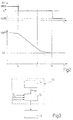
- Figure 2 illustrates the temporal development of the position x(t) of the clutch 4, and the temporal development of the angular speed ⁇ m (t) of the drive shaft 10, during the phase of reclosure of the clutch 4; in particular, engagement of the gear B is completed at an instant t 0 , corresponding to which the clutch 4 is adjusted rapidly from a position of opening to a predetermined intermediate position, in order to transmit constant torque T cl * (substantially equal to the drive torque T* supplied by the engine 2, immediately before the change of gear).
- the clutch 4 is kept in the predetermined position x* until an instant t 2 , in which synchronisation of the drive shaft 10 and the primary shaft 7 is completed; at the instant t 2 , the clutch is reclosed fully, and the change of gear is completed.
- the engine 2 is regulated by the control unit 13, in order to increase progressively the torque T m (t) supplied, such as to vary the angular speed ⁇ m (t) of the drive shaft 10 according to a law of motion of a parabolic type, which is substantially tangent to the angular speed ⁇ 1 (t) of the primary shaft 7 (angular speed ⁇ 1 (t) substantially constant in the interval of time considered).
- the angular speed ⁇ m (t) of the drive shaft 10 before the instant t 0 has a drift ⁇ ' m (t) over a period of time which is constant and slightly negative, as can be seen clearly from the equation [2], since the torque T cl (t) transmitted by the clutch 4 is zero, and the drive torque T m (t) generated by the engine 2 is slightly negative, owing to the effect of the friction torques (the power supply to the engine 2 is stopped, and the engine is not producing useful torque).
- the angular speed ⁇ m (t) of the drive shaft 10 before the instant t 0 has a linear law of motion, with a slightly negative gradient.
- the angular speed ⁇ m (t) of the drive shaft 10 between the instant to and the instant t 1 has a drift ⁇ ' m (t) over a period of time which is constant and is strongly negative, as can be seen clearly from the equation [2], since the torque T cl (t) transmitted by the clutch 4 is constant, and is equal to the drive torque T* supplied by the engine 2, immediately before the change of gear, and the drive torque T m (t) generated by the engine 2 is slightly negative, owing to the effect of the friction torques (the power supply to the engine is stopped, and the engine is not producing useful torque).
- the angular speed ⁇ m (t) of the drive shaft 10 between the instant t 0 and the instant t 1 has a linear law of motion, with a pronounced negative gradient.
- the angular speed ⁇ m (t) of the drive shaft 10 between the instant t 1 and the instant t 2 has a negative drift ⁇ m (t), and a modulus which decreases in a linear manner over a period of time, owing to the effect of the progressive increase of the drive torque T m (t) generated by the engine 2, under the control of the control unit 13.
- the torque T cl (t) transmitted by the clutch 4 is constant, and is equal to the drive torque T* supplied by the engine 2, immediately before the change of gear, and the drive torque T m (t) generated by the engine 2 increases in a linear manner, owing to the effect of the regulations applied by the control unit 13.
- the angular speed ⁇ m (t) of the drive shaft 10 between the instant t 1 and the instant t 2 has a parabolic law of motion; in fact, if the drift ⁇ ' m (t) of the angular speed ⁇ m (t) has a linear increase over a period of time, the angular speed ⁇ m (t) has a law of motion of a parabolic type.
- the law of motion of the angular speed ⁇ m (t) need not be a law of a parabolic type.
- use of a law of a parabolic type is particularly advantageous, since the law of a parabolic type makes it possible to adjust the angular speed ⁇ m (t) until it is synchronised with the angular speed ⁇ 1 (t) in an extremely gentle and gradual manner (since the parabola of the angular speed ⁇ m (t) is designated such as to be substantially tangent to the straight line of the angular speed ⁇ 1 (t); in addition, the creation of a parabolic law of motion is relatively simple, since it requires the drift ⁇ ' m (t) of the angular speed ⁇ m (t) to have an increase which is linear over a period of time, i.e. (on the basis of the equation [2]), it requires the drive torque T m (t) generated by the engine 2 to have an increase which is linear over a period of
- control unit 13 comprises a generation block 14, which, starting from the instant t 1 , generates a reference signal ⁇ mrif (t), which indicates the ideal development which the angular speed ⁇ m (t) should assume between the instant t 1 and the instant t 2 .
- the control unit 13 additionally comprises a piloting block 15, which receives as input the reference signal ⁇ mrif (t), the reading of the angular speed ⁇ (t), the reading of the drift ⁇ ' m (t) of the angular speed ⁇ m (t), and the reading of the torque T cl (t) transmitted by the clutch 4, and can pilot the engine 2 such as to make the angular speed ⁇ m (t) follow the development of the reference signal ⁇ mrif (t), within a predetermined tolerance.
- the piloting block 15 controls the torque of the engine 2, i.e. it communicates to a control system (which is known and not illustrated) of the engine 2 the value of the objective torque T mob (t) which the engine 2 must supply, such that the angular speed ⁇ m (t) follows the development of the reference signal ⁇ mrif (t).
- the value of the objective torque T mob (t) is determined by the piloting block 15, by means of the sum of two contributions T mob1 (t) and T mob2 (t) which are independent from one another; the value T mob1 (t) is determined by means of an open-loop control logic, on the basis of the torque T cl (t) transmitted by the clutch 4, whereas the value T mob2 (t) is determined by means of a closed-loop logic, on the basis of the difference between the angular speed ⁇ m (t) and the reference signal ⁇ mrif (t).
- the value of the objective torque is determined by applying the equations [4], [5] and [6] listed below, in which K is the coefficient of gain, which depends on the operative condition.
- K is the coefficient of gain, which depends on the operative condition.
- T mob (t) T mob1 (t) + T mob2 (t)
- T mob1 (t) K * ( ⁇ mrif (t) - ⁇ m (t))
- T mob2 (t) T cl (t) + J m * ⁇ ' m (t)
Landscapes
- Engineering & Computer Science (AREA)
- Chemical & Material Sciences (AREA)
- Combustion & Propulsion (AREA)
- Transportation (AREA)
- Mechanical Engineering (AREA)
- Automation & Control Theory (AREA)
- Control Of Transmission Device (AREA)
- Hydraulic Clutches, Magnetic Clutches, Fluid Clutches, And Fluid Joints (AREA)
- Gear-Shifting Mechanisms (AREA)
- Hybrid Electric Vehicles (AREA)
Applications Claiming Priority (2)
| Application Number | Priority Date | Filing Date | Title |
|---|---|---|---|
| ITBO000625 | 2000-10-27 | ||
| IT2000BO000625A ITBO20000625A1 (it) | 2000-10-27 | 2000-10-27 | Metodo di richiusura della frizione durante un cambio marcia |
Publications (2)
| Publication Number | Publication Date |
|---|---|
| EP1201481A1 true EP1201481A1 (de) | 2002-05-02 |
| EP1201481B1 EP1201481B1 (de) | 2004-08-11 |
Family
ID=11438815
Family Applications (1)
| Application Number | Title | Priority Date | Filing Date |
|---|---|---|---|
| EP01125658A Expired - Lifetime EP1201481B1 (de) | 2000-10-27 | 2001-10-26 | Methode zum Schliessen einer Kupplung während des Schaltens |
Country Status (6)
| Country | Link |
|---|---|
| US (1) | US6676568B2 (de) |
| EP (1) | EP1201481B1 (de) |
| BR (1) | BR0105840B1 (de) |
| DE (1) | DE60104797T2 (de) |
| ES (1) | ES2225383T3 (de) |
| IT (1) | ITBO20000625A1 (de) |
Families Citing this family (1)
| Publication number | Priority date | Publication date | Assignee | Title |
|---|---|---|---|---|
| GB2470015B (en) * | 2009-05-05 | 2016-05-18 | Gm Global Tech Operations Llc | Method and apparatus for estimating clutch friction |
Citations (5)
| Publication number | Priority date | Publication date | Assignee | Title |
|---|---|---|---|---|
| DE4204401A1 (de) * | 1992-02-14 | 1993-08-19 | Bosch Gmbh Robert | Einrichtung zur steuerung des abtriebsmoments eines automatischen schaltgetriebes |
| US5638271A (en) * | 1995-01-04 | 1997-06-10 | Cummins Engine Company, Inc. | Apparatus and method for assisting gear engagement in controlling the automatic shifting of a manual-automatic transmission |
| DE19725149A1 (de) * | 1996-06-15 | 1997-12-18 | Luk Getriebe Systeme Gmbh | Kraftfahrzeug |
| DE19712871A1 (de) * | 1997-03-27 | 1998-10-01 | Bosch Gmbh Robert | Kupplungssystem |
| US6061619A (en) * | 1992-09-09 | 2000-05-09 | Luk Lamellen Und Kupplungsbau Gmbh | Electronic clutch management |
Family Cites Families (6)
| Publication number | Priority date | Publication date | Assignee | Title |
|---|---|---|---|---|
| FR2458721A1 (fr) * | 1979-06-08 | 1981-01-02 | Peugeot | Mecanisme de transmission comportant un embrayage et une boite de vitesses a plusieurs rapports |
| US5206805A (en) * | 1987-03-13 | 1993-04-27 | Borg-Warner Automotive, Inc. | Continuously variable transmission clutch control system including special start mode operation |
| DE19628787C2 (de) * | 1996-07-17 | 2002-11-14 | Luk Gs Verwaltungs Kg | Automatisch steuerbare Kupplung |
| US6319173B1 (en) * | 1997-04-16 | 2001-11-20 | Transmisiones Tsp, S.A. De C.V. | Method and apparatus for operating a clutch in an automated mechanical transmission |
| IT1293853B1 (it) * | 1997-06-25 | 1999-03-10 | Magneti Marelli Spa | Metodo e dispositivo di controllo di un gruppo di trasmissione di un veicolo. |
| DE19806497C2 (de) * | 1998-02-17 | 2000-03-16 | Mannesmann Sachs Ag | Antriebsanordnung für ein von einem Verbrennungsmotor angetriebenes Kraftfahrzeug |
-
2000
- 2000-10-27 IT IT2000BO000625A patent/ITBO20000625A1/it unknown
-
2001
- 2001-10-24 BR BRPI0105840-1A patent/BR0105840B1/pt not_active IP Right Cessation
- 2001-10-25 US US09/983,761 patent/US6676568B2/en not_active Expired - Lifetime
- 2001-10-26 ES ES01125658T patent/ES2225383T3/es not_active Expired - Lifetime
- 2001-10-26 EP EP01125658A patent/EP1201481B1/de not_active Expired - Lifetime
- 2001-10-26 DE DE60104797T patent/DE60104797T2/de not_active Expired - Lifetime
Patent Citations (5)
| Publication number | Priority date | Publication date | Assignee | Title |
|---|---|---|---|---|
| DE4204401A1 (de) * | 1992-02-14 | 1993-08-19 | Bosch Gmbh Robert | Einrichtung zur steuerung des abtriebsmoments eines automatischen schaltgetriebes |
| US6061619A (en) * | 1992-09-09 | 2000-05-09 | Luk Lamellen Und Kupplungsbau Gmbh | Electronic clutch management |
| US5638271A (en) * | 1995-01-04 | 1997-06-10 | Cummins Engine Company, Inc. | Apparatus and method for assisting gear engagement in controlling the automatic shifting of a manual-automatic transmission |
| DE19725149A1 (de) * | 1996-06-15 | 1997-12-18 | Luk Getriebe Systeme Gmbh | Kraftfahrzeug |
| DE19712871A1 (de) * | 1997-03-27 | 1998-10-01 | Bosch Gmbh Robert | Kupplungssystem |
Also Published As
| Publication number | Publication date |
|---|---|
| US6676568B2 (en) | 2004-01-13 |
| ITBO20000625A0 (it) | 2000-10-27 |
| US20020077215A1 (en) | 2002-06-20 |
| DE60104797D1 (de) | 2004-09-16 |
| BR0105840B1 (pt) | 2009-05-05 |
| DE60104797T2 (de) | 2005-09-29 |
| BR0105840A (pt) | 2002-06-25 |
| EP1201481B1 (de) | 2004-08-11 |
| ITBO20000625A1 (it) | 2002-04-27 |
| ES2225383T3 (es) | 2005-03-16 |
Similar Documents
| Publication | Publication Date | Title |
|---|---|---|
| EP1522764B1 (de) | Fahrzeuggangschaltersteuerung | |
| JP4594331B2 (ja) | 自動車の駆動歯車列においてトルク伝動する少なくとも二つの並列なクラッチを作動する方法と伝動装置制御部 | |
| US9037326B2 (en) | Method for disconnecting an electrical machine on a running gear of a vehicle, in particular a hybrid motor vehicle | |
| JP4867054B2 (ja) | ギアチェンジを制御する方法およびギアチェンジを制御する装置 | |
| US6966868B2 (en) | Method for adapting the adjustment of a clutch in an unconventional drive train of a vehicle | |
| US8109855B2 (en) | Method for controlling the coupling and the decoupling of the first motor and second motor of a parallel hybrid motive power group | |
| US6128564A (en) | Controller for a drive train of a motor vehicle | |
| CN102803041B (zh) | 车辆的变速控制装置 | |
| JP5177277B2 (ja) | 変速機の制御装置 | |
| CN107487318B (zh) | 用于控制车辆动力传动系的系统和方法 | |
| US6675083B2 (en) | Method for restoration of the drive torque during a change of gear | |
| EP0403127B1 (de) | Automatische Gangwechsel-Steuereinrichtung für Kraftfahrzeuge und Verfahren zur Steuerung | |
| US5678674A (en) | Control device for regulating the engaging process of a separating clutch for motor vehicles | |
| JP3445890B2 (ja) | クラッチ制御装置 | |
| ITBO20000627A1 (it) | Metodo per l'esecuzione del disinnesto marcia in un cambio manuale servocomandato | |
| JP2921569B2 (ja) | 回転数を同期させるための方法および装置 | |
| JP2004525326A (ja) | 伝動システム | |
| US6676568B2 (en) | Method for reclosure of the clutch during a change of gear | |
| JP4071964B2 (ja) | 車両のドライブトレインのクラッチの駆動方法および車両のドライブトレインのクラッチの制御装置 | |
| US20220289043A1 (en) | Regenerative braking torque control system for launch clutch opening | |
| KR20200083688A (ko) | 수동변속기 차량의 운전 제어방법 및 장치 | |
| JP2001055937A (ja) | 車両のドライブトレインの制御方法および車両のドライブトレインの制御装置 | |
| JPS62255250A (ja) | 自動車の走行制御装置 |
Legal Events
| Date | Code | Title | Description |
|---|---|---|---|
| PUAI | Public reference made under article 153(3) epc to a published international application that has entered the european phase |
Free format text: ORIGINAL CODE: 0009012 |
|
| AK | Designated contracting states |
Kind code of ref document: A1 Designated state(s): DE ES FR GB SE Kind code of ref document: A1 Designated state(s): AT BE CH CY DE DK ES FI FR GB GR IE IT LI LU MC NL PT SE TR |
|
| AX | Request for extension of the european patent |
Free format text: AL;LT;LV;MK;RO;SI |
|
| 17P | Request for examination filed |
Effective date: 20021029 |
|
| AKX | Designation fees paid |
Free format text: DE ES FR GB SE |
|
| 17Q | First examination report despatched |
Effective date: 20030807 |
|
| GRAP | Despatch of communication of intention to grant a patent |
Free format text: ORIGINAL CODE: EPIDOSNIGR1 |
|
| GRAS | Grant fee paid |
Free format text: ORIGINAL CODE: EPIDOSNIGR3 |
|
| GRAA | (expected) grant |
Free format text: ORIGINAL CODE: 0009210 |
|
| RAP1 | Party data changed (applicant data changed or rights of an application transferred) |
Owner name: MAGNETI MARELLI POWERTRAIN S.P.A. |
|
| AK | Designated contracting states |
Kind code of ref document: B1 Designated state(s): DE ES FR GB SE |
|
| REG | Reference to a national code |
Ref country code: GB Ref legal event code: FG4D |
|
| REG | Reference to a national code |
Ref country code: IE Ref legal event code: FG4D |
|
| REF | Corresponds to: |
Ref document number: 60104797 Country of ref document: DE Date of ref document: 20040916 Kind code of ref document: P |
|
| REG | Reference to a national code |
Ref country code: SE Ref legal event code: TRGR |
|
| REG | Reference to a national code |
Ref country code: ES Ref legal event code: FG2A Ref document number: 2225383 Country of ref document: ES Kind code of ref document: T3 |
|
| ET | Fr: translation filed | ||
| PLBE | No opposition filed within time limit |
Free format text: ORIGINAL CODE: 0009261 |
|
| STAA | Information on the status of an ep patent application or granted ep patent |
Free format text: STATUS: NO OPPOSITION FILED WITHIN TIME LIMIT |
|
| 26N | No opposition filed |
Effective date: 20050512 |
|
| REG | Reference to a national code |
Ref country code: FR Ref legal event code: PLFP Year of fee payment: 16 |
|
| REG | Reference to a national code |
Ref country code: FR Ref legal event code: PLFP Year of fee payment: 17 |
|
| REG | Reference to a national code |
Ref country code: FR Ref legal event code: PLFP Year of fee payment: 18 |
|
| PGFP | Annual fee paid to national office [announced via postgrant information from national office to epo] |
Ref country code: FR Payment date: 20200917 Year of fee payment: 20 Ref country code: GB Payment date: 20200921 Year of fee payment: 20 |
|
| PGFP | Annual fee paid to national office [announced via postgrant information from national office to epo] |
Ref country code: SE Payment date: 20200923 Year of fee payment: 20 |
|
| PGFP | Annual fee paid to national office [announced via postgrant information from national office to epo] |
Ref country code: DE Payment date: 20200917 Year of fee payment: 20 Ref country code: ES Payment date: 20201102 Year of fee payment: 20 |
|
| REG | Reference to a national code |
Ref country code: DE Ref legal event code: R071 Ref document number: 60104797 Country of ref document: DE |
|
| REG | Reference to a national code |
Ref country code: GB Ref legal event code: PE20 Expiry date: 20211025 |
|
| REG | Reference to a national code |
Ref country code: SE Ref legal event code: EUG |
|
| PG25 | Lapsed in a contracting state [announced via postgrant information from national office to epo] |
Ref country code: GB Free format text: LAPSE BECAUSE OF EXPIRATION OF PROTECTION Effective date: 20211025 |
|
| REG | Reference to a national code |
Ref country code: ES Ref legal event code: FD2A Effective date: 20220204 |
|
| PG25 | Lapsed in a contracting state [announced via postgrant information from national office to epo] |
Ref country code: ES Free format text: LAPSE BECAUSE OF EXPIRATION OF PROTECTION Effective date: 20211027 |