EP1199528A2 - Steckdose für ein Bratenthermometer - Google Patents
Steckdose für ein Bratenthermometer Download PDFInfo
- Publication number
- EP1199528A2 EP1199528A2 EP01123796A EP01123796A EP1199528A2 EP 1199528 A2 EP1199528 A2 EP 1199528A2 EP 01123796 A EP01123796 A EP 01123796A EP 01123796 A EP01123796 A EP 01123796A EP 1199528 A2 EP1199528 A2 EP 1199528A2
- Authority
- EP
- European Patent Office
- Prior art keywords
- socket
- plug
- cooking space
- closure element
- steam oven
- Prior art date
- Legal status (The legal status is an assumption and is not a legal conclusion. Google has not performed a legal analysis and makes no representation as to the accuracy of the status listed.)
- Granted
Links
Images

Classifications
-
- F—MECHANICAL ENGINEERING; LIGHTING; HEATING; WEAPONS; BLASTING
- F24—HEATING; RANGES; VENTILATING
- F24C—DOMESTIC STOVES OR RANGES ; DETAILS OF DOMESTIC STOVES OR RANGES, OF GENERAL APPLICATION
- F24C7/00—Stoves or ranges heated by electric energy
- F24C7/08—Arrangement or mounting of control or safety devices
Definitions
- the invention relates to a steam oven with a cooking space, which has an outlet for Inclusion of a plug for a temperature sensor arranged in the cooking space with a Insertion opening to the cooking space and the insertion opening in the absence of the Includes plug-closing closure element loaded with a spring.
- the object of the present invention based on developing a steam oven of the aforementioned type so that the mentioned disadvantages can be avoided.
- This object is achieved in that the closure element through the Insertion movement and in the insertion direction of the plug can be folded away. So that's it for the user no longer needs an additional handle on the Closure element or a facial expression interacting with it.
- the Folding away in the direction of the insertion movement of the stretcher is furthermore energy-saving, since the movement of the plug is used directly.
- the closure element is on the outside of the Arranged cooking space. On this side there is very little risk of facial expressions and thus the function of the closure element due to the high temperature of the Cooking space, due to the moisture occurring in it or due to possible Residues of the food to be cooked such as fat splashes are impaired.
- closure element has a conical section has the insertion opening of the socket in the absence of the plug closes and prevents steam from escaping from the cooking space.
- the conical section of the closure element is on itself in the closed position extending largely parallel to the wall of the cooking space arranged at an angle.
- Another advantage is a holding element for pivoting outside the cooking space Arrangement of the second leg of the angle to which the angle is attached is and the arrangement of which allows the folding movement of the closure element.
- the holding element is on a socket of the socket arranged and thus usable with the socket as a unit in the steam oven.
- the spring is on the holding element and on the leg arranged to act on the conical section. So the entire outlet including the facial expressions for the closure element in one piece and as a component in the Steam oven can be used.
- the plug is advantageously subjected to cooling air in its insertion position, as a result any steam entering the socket in the operating position on the cooled
- the connector is condensed and the water film that forms on the connector has an additional sealing function.
- Fig. 1 shows a schematic representation of a steam oven 1 with a closed cooking space 2 and a cooking item 3 arranged in the cooking space 2
- a socket 4 is arranged on the outside of the side wall 2b of the cooking space 2 reach through at least parts of the socket through the outside of the cooking space. Through the Arrangement on the outside ensures that the in the socket 4 arranged contacts are not affected by the conditions in the cooking space 2.
- a temperature sensor 5 is provided has a cable 6 and a plug 7 connected to it. Between the Socket 4 and the cooking space has an opening 10 (FIG. 2) through which the plug 7 can be manually inserted into the socket 4 from the cooking space 2.
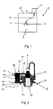
- Fig. 2 shows the socket 4 with a socket 8 and a closure element 9 for the Insert opening 10.
- the closure element 9 has a conical design Section 11 and a closure bracket 13.
- the conical section 11 is on one leg 12 of a closure bracket 13 is arranged.
- the line of symmetry of the conical section 11 extends largely orthogonally the leg 12 of the closure bracket 13.
- the conical section 11 is included its side facing away from the insertion opening on the leg 12 so that even if the conical section 11 penetrates deeper into the insertion opening 10 the leg 12 does not come to rest with the border 14 of the insertion opening 10 can.
- the second leg 15 of the arranged perpendicular to the leg 12 Closure angle 13 is pivotally arranged on a holding element 16.
- the Holding element 16 is integrated into the socket 8 of the socket 4. It is angular formed, one leg 16a perpendicular and a second leg 16b parallel extends to the insertion opening 10.
- the leg 15 of the closure bracket 12 is on the leg 16b of the holding element arranged parallel to the insertion opening 10 16 articulated, the closure angle about an articulation point 18 on the leg 16b is pivotable.
- the leg 16a lies on the outside of the side wall 2b of the Oven.
- one leg 17a is also one Leg spring 17 arranged, the second leg 17b in operative connection with the Leg 12 of the closure bracket 13 is operatively connected. The spring force of the Leg spring 17 presses the conical section 11 of the closure element 9 into the Insert opening 10 and closes the socket 4 compared to that shown in Fig. 1 Oven.
- FIG. 3 shows the socket 8 shown in FIG. 2 with the plug 7 inserted. From the cooking space 2 the plug is through the side wall of the cooking space and the insertion opening 10 of the Socket 8 out. The front end 19 of the plug 7 pushes through the manual Insert the plug 7 into the insertion opening 10 the conical section 11 of the Closure element 9 on the opposite side of the insertion opening from this out.
- the closure element 9 is against the spring force of the leg spring 17th pivoted about the pivot point 18.
- the against the spring force of the leg spring 17th deflected closure element 9 is through the front part 19 of the plug 7 in held in this position while the plug 7 itself from the socket 8 of the socket 4th is held. The user only has to hold the plug 7 in his hand to take.
- a separate actuation of the closure element 9 or one on this acting facial expressions is not necessary in the configuration according to the invention.
- this plug position is the plug 7 with contacts 20 and 21 of the socket and thus in connection with the electronic control of the steam oven, not shown, which which are picked up by the temperature sensor and via the cable and the plug 7 transmitted data used to control the conditions in the cooking space.
- the In this position steam penetration is largely prevented by the in the insertion opening 10 of the socket 8 located connector 7 prevented.
- Such Plug connection is not without the provision of an additional seal completely impermeable to steam, but the penetration of hot and humid steam into the socket can impair the functionality of the electronics. Therefore, the device cooling required to cool the free in the anyway Socket protruding front part 19 of the connector 7 used.
Landscapes
- Engineering & Computer Science (AREA)
- Chemical & Material Sciences (AREA)
- Combustion & Propulsion (AREA)
- Mechanical Engineering (AREA)
- General Engineering & Computer Science (AREA)
- Baking, Grill, Roasting (AREA)
- Cookers (AREA)
- Meat, Egg Or Seafood Products (AREA)
- Seeds, Soups, And Other Foods (AREA)
- Control And Other Processes For Unpacking Of Materials (AREA)
- Mechanical Coupling Of Light Guides (AREA)
- Measuring Temperature Or Quantity Of Heat (AREA)
Abstract
Description
- Fig. 1
- einen schematischen Aufbau eines Dampfbackofens im Querschnitt
- Fig. 2
- eine Steckdose im Verschlusszustand bei gezogenem Stecker im Querschnitt
- Fig. 3
- die Steckdose mit eingestecktem Stecker im Querschnitt
- 1
- Dampfbackofen
- 2
- Garraum
- 2b
- Seitenwand Garraum
- 3
- Gargut
- 4
- Steckdose
- 5
- Temperaturfühler
- 6
- Kabel
- 7
- Stecker
- 8
- Buchse
- 9
- Verschlusselement
- 10
- Einstecköffnung
- 11
- konischer Abschnitt des Verschlusselements
- 12
- Schenkel des Verschlusswinkels
- 13
- Verschlusswinkel
- 14
- Umrandung
- 15
- Schenkel des Verschlusswinkels
- 16
- Halteelement
- 17,17a,17b
- Schenkelfeder
- 18
- Anlenkung
- 19
- vorderer Teil des Steckers
- 20,21
- elektrische Kontakte
Claims (9)
- Dampfbackofen mit einem Garraum, der eine Steckdose zur Aufnahme eines Steckers eines im Garraum angeordneten Temperaturfühlers mit einer Einstecköffnung zum Garraum und einem die Einstecköffnung bei Abwesenheit des Steckers verschließenden, mit einer Feder belasteten Verschlusselement enthält,
dadurch gekennzeichnet, dass
das Verschlusselement (9) durch die Einsteckbewegung und in Einsteckrichtung des Steckers (7) wegklappbar ist. - Dampfbackofen nach Anspruch 1, dadurch gekennzeichnet, dass das Verschlusselement (9) an der Außenseite des Garraums (2) angeordnet ist.
- Dampfbackofen nach Anspruch 1 oder 2, dadurch gekennzeichnet, dass das Verschlusselement (9) einen konisch ausgebildeten Abschnitt (11) aufweist.
- Dampfbackofen nach einem der Ansprüche 1 bis 3, dadurch gekennzeichnet, dass der konische Abschnitt (11) des Verschlusselements (9) an einem sich in Schließstellung weitgehend parallel zur Wand (2b) des Garraums (2) erstreckenden Schenkel (12) eines Winkels (13) angeordnet ist.
- Dampfbackofen nach einem der Ansprüche 1 bis 4, dadurch gekennzeichnet, dass außerhalb des Garraums (2) ein Halteelement (16) zur schwenkbaren Anordnung des zweiten Schenkels (15) des Winkels (13) angeordnet ist.
- Dampfbackofen nach einem der Ansprüche 1 bis 5, dadurch gekennzeichnet, dass das Halteelement (16) an einer Buchse (8) der Steckdose (4) angeordnet ist.
- Dampfbackofen nach einem der Ansprüche 1 bis 6, dadurch gekennzeichnet, dass die Feder (17) an dem Halteelement (16) und über den Schenkel (12) auf den konischen Abschnitt (11) des Verschlusselements (9) einwirkend angeordnet ist.
- Dampfbackofen nach einem der Ansprüche 1 bis 7, dadurch gekennzeichnet, dass zumindest der in die Buchse (8) der Steckdose (4) eingreifende vordere Teil (19) des Steckers (7) in seiner Einsteckposition mit Kühlluft beaufschlagt ist.
- Dampfbackofen nach Anspruch 8, dadurch gekennzeichnet, dass als Kühlluft die zur Kühlung des Dampfbackofens notwendige Kühlluft ist.
Applications Claiming Priority (2)
| Application Number | Priority Date | Filing Date | Title |
|---|---|---|---|
| DE10051511A DE10051511A1 (de) | 2000-10-17 | 2000-10-17 | Steckdose für ein Bratenthermometer |
| DE10051511 | 2000-10-17 |
Publications (3)
| Publication Number | Publication Date |
|---|---|
| EP1199528A2 true EP1199528A2 (de) | 2002-04-24 |
| EP1199528A3 EP1199528A3 (de) | 2004-09-22 |
| EP1199528B1 EP1199528B1 (de) | 2007-01-03 |
Family
ID=7660133
Family Applications (1)
| Application Number | Title | Priority Date | Filing Date |
|---|---|---|---|
| EP01123796A Expired - Lifetime EP1199528B1 (de) | 2000-10-17 | 2001-10-04 | Steckdose für ein Bratenthermometer |
Country Status (3)
| Country | Link |
|---|---|
| EP (1) | EP1199528B1 (de) |
| AT (1) | ATE350626T1 (de) |
| DE (2) | DE10051511A1 (de) |
Cited By (3)
| Publication number | Priority date | Publication date | Assignee | Title |
|---|---|---|---|---|
| EP1536182A1 (de) * | 2003-11-26 | 2005-06-01 | BSH Bosch und Siemens Hausgeräte GmbH | Steckdose für einen in einem Backofen angeordneten Temperaturfühler |
| EP1950498A1 (de) * | 2007-01-23 | 2008-07-30 | Electrolux Home Products Corporation N.V. | Ofen |
| DE102015205489A1 (de) | 2015-03-26 | 2016-09-29 | BSH Hausgeräte GmbH | Haushaltsgerät |
Families Citing this family (1)
| Publication number | Priority date | Publication date | Assignee | Title |
|---|---|---|---|---|
| DE102023212220A1 (de) | 2023-12-05 | 2025-06-05 | BSH Hausgeräte GmbH | Haushalts-Gargerät mit Steckdose für Zubehör |
Family Cites Families (5)
| Publication number | Priority date | Publication date | Assignee | Title |
|---|---|---|---|---|
| JPS5368451A (en) * | 1976-11-30 | 1978-06-17 | Sharp Corp | Electronic oven |
| WO1985002456A1 (en) * | 1983-11-22 | 1985-06-06 | Matsushita Electric Industrial Co., Ltd. | Apparatus for rotatably supporting temperature probe |
| DE9016885U1 (de) * | 1990-12-14 | 1991-08-14 | Licentia Patent-Verwaltungs-Gmbh, 6000 Frankfurt | Anschlußeinrichtung für eine Temperaturmeßsonde im Back- und Bratraum von Herden |
| JPH04283320A (ja) * | 1991-03-12 | 1992-10-08 | Sharp Corp | 電子レンジ |
| FR2723268A1 (fr) * | 1994-07-28 | 1996-02-02 | Alcatel Cable Interface Sa | Connecteur femelle protege contre des pertubations, pour reseau de communication |
-
2000
- 2000-10-17 DE DE10051511A patent/DE10051511A1/de not_active Withdrawn
-
2001
- 2001-10-04 EP EP01123796A patent/EP1199528B1/de not_active Expired - Lifetime
- 2001-10-04 DE DE50111778T patent/DE50111778D1/de not_active Expired - Lifetime
- 2001-10-04 AT AT01123796T patent/ATE350626T1/de not_active IP Right Cessation
Cited By (3)
| Publication number | Priority date | Publication date | Assignee | Title |
|---|---|---|---|---|
| EP1536182A1 (de) * | 2003-11-26 | 2005-06-01 | BSH Bosch und Siemens Hausgeräte GmbH | Steckdose für einen in einem Backofen angeordneten Temperaturfühler |
| EP1950498A1 (de) * | 2007-01-23 | 2008-07-30 | Electrolux Home Products Corporation N.V. | Ofen |
| DE102015205489A1 (de) | 2015-03-26 | 2016-09-29 | BSH Hausgeräte GmbH | Haushaltsgerät |
Also Published As
| Publication number | Publication date |
|---|---|
| DE10051511A1 (de) | 2002-04-25 |
| ATE350626T1 (de) | 2007-01-15 |
| DE50111778D1 (de) | 2007-02-15 |
| EP1199528A3 (de) | 2004-09-22 |
| EP1199528B1 (de) | 2007-01-03 |
Similar Documents
| Publication | Publication Date | Title |
|---|---|---|
| DE102015116074B4 (de) | Staubsauger | |
| DE19609522C2 (de) | Steckverbinder mit verrastbarer Zusatzverriegelung | |
| DE69915010T2 (de) | Kühlungsvorrichtung, Kühlungsverfahren und elektronisches Gerät | |
| DE102012007911B4 (de) | Elektrische Steckverbindung | |
| DE19858467B4 (de) | Steckverbinderanordnung mit einem geschützten Verriegelungsarm | |
| EP2917970B1 (de) | Federkraftklemme mit einem betätigungsmittel | |
| DE202010012730U1 (de) | Topf mit einem Deckel-Hebemechanismus | |
| WO2017036445A1 (de) | Halterahmen mit rückstellkraft für steckverbindermodule | |
| EP3707784B1 (de) | Steckverbindergehäuse mit einem schwenkbaren verriegelungsbügel | |
| DE202020100637U1 (de) | Fahrzeug-Lademodul | |
| DE102017122446B3 (de) | Elektrisches Gerät | |
| WO2017102901A1 (de) | Steckverbinderteil mit einem abdeckelement | |
| EP1199528A2 (de) | Steckdose für ein Bratenthermometer | |
| DE102017104671A1 (de) | Endoskophandgriff und Endoskop | |
| EP0045036B1 (de) | Staubsauger mit einem den Staubraum abschliessenden Deckel | |
| DE60038472T2 (de) | Steckverbinder mit Kabelzugentlastung | |
| EP0345681A2 (de) | Verschlusseinrichtung für eine Heissgerätetür | |
| DE19938812A1 (de) | Elektronischer Heizkostenverteiler | |
| DE10255531B3 (de) | Stecker mit Schieber zum Verbinden mit einer Steckbuchse | |
| DE102008013698B4 (de) | Lanze zur Aufnahme eines Sensors oder Probennehmers für Metallschmelzen | |
| DE69519642T2 (de) | Elektrisches Steckergehäuse mit verbesserter Verriegelungsvorrichtung | |
| DE20221895U1 (de) | Kontakt mit Federklemme | |
| DE102005044720B4 (de) | Aufnahmehalter für einen Telefonhalter | |
| DE60123690T2 (de) | Steckverbinder | |
| DE202009007297U1 (de) | Staubsauger |
Legal Events
| Date | Code | Title | Description |
|---|---|---|---|
| PUAI | Public reference made under article 153(3) epc to a published international application that has entered the european phase |
Free format text: ORIGINAL CODE: 0009012 |
|
| AK | Designated contracting states |
Kind code of ref document: A2 Designated state(s): AT BE CH CY DE DK ES FI FR GB GR IE IT LI LU MC NL PT SE TR |
|
| AX | Request for extension of the european patent |
Free format text: AL;LT;LV;MK;RO;SI |
|
| RAP1 | Party data changed (applicant data changed or rights of an application transferred) |
Owner name: BSH BOSCH UND SIEMENS HAUSGERAETE GMBH |
|
| PUAL | Search report despatched |
Free format text: ORIGINAL CODE: 0009013 |
|
| AK | Designated contracting states |
Kind code of ref document: A3 Designated state(s): AT BE CH CY DE DK ES FI FR GB GR IE IT LI LU MC NL PT SE TR |
|
| AX | Request for extension of the european patent |
Extension state: AL LT LV MK RO SI |
|
| 17P | Request for examination filed |
Effective date: 20050322 |
|
| AKX | Designation fees paid |
Designated state(s): AT BE CH CY DE DK ES FI FR GB GR IE IT LI LU MC NL PT SE TR |
|
| GRAP | Despatch of communication of intention to grant a patent |
Free format text: ORIGINAL CODE: EPIDOSNIGR1 |
|
| GRAS | Grant fee paid |
Free format text: ORIGINAL CODE: EPIDOSNIGR3 |
|
| GRAL | Information related to payment of fee for publishing/printing deleted |
Free format text: ORIGINAL CODE: EPIDOSDIGR3 |
|
| GRAS | Grant fee paid |
Free format text: ORIGINAL CODE: EPIDOSNIGR3 |
|
| GRAA | (expected) grant |
Free format text: ORIGINAL CODE: 0009210 |
|
| AK | Designated contracting states |
Kind code of ref document: B1 Designated state(s): AT BE CH CY DE DK ES FI FR GB GR IE IT LI LU MC NL PT SE TR |
|
| PG25 | Lapsed in a contracting state [announced via postgrant information from national office to epo] |
Ref country code: FI Free format text: LAPSE BECAUSE OF FAILURE TO SUBMIT A TRANSLATION OF THE DESCRIPTION OR TO PAY THE FEE WITHIN THE PRESCRIBED TIME-LIMIT Effective date: 20070103 Ref country code: DK Free format text: LAPSE BECAUSE OF FAILURE TO SUBMIT A TRANSLATION OF THE DESCRIPTION OR TO PAY THE FEE WITHIN THE PRESCRIBED TIME-LIMIT Effective date: 20070103 Ref country code: NL Free format text: LAPSE BECAUSE OF FAILURE TO SUBMIT A TRANSLATION OF THE DESCRIPTION OR TO PAY THE FEE WITHIN THE PRESCRIBED TIME-LIMIT Effective date: 20070103 Ref country code: IE Free format text: LAPSE BECAUSE OF FAILURE TO SUBMIT A TRANSLATION OF THE DESCRIPTION OR TO PAY THE FEE WITHIN THE PRESCRIBED TIME-LIMIT Effective date: 20070103 |
|
| REG | Reference to a national code |
Ref country code: GB Ref legal event code: FG4D Free format text: NOT ENGLISH |
|
| GBT | Gb: translation of ep patent filed (gb section 77(6)(a)/1977) |
Effective date: 20070117 |
|
| REF | Corresponds to: |
Ref document number: 50111778 Country of ref document: DE Date of ref document: 20070215 Kind code of ref document: P |
|
| REG | Reference to a national code |
Ref country code: IE Ref legal event code: FG4D Free format text: LANGUAGE OF EP DOCUMENT: GERMAN |
|
| PG25 | Lapsed in a contracting state [announced via postgrant information from national office to epo] |
Ref country code: SE Free format text: LAPSE BECAUSE OF FAILURE TO SUBMIT A TRANSLATION OF THE DESCRIPTION OR TO PAY THE FEE WITHIN THE PRESCRIBED TIME-LIMIT Effective date: 20070403 |
|
| PG25 | Lapsed in a contracting state [announced via postgrant information from national office to epo] |
Ref country code: ES Free format text: LAPSE BECAUSE OF FAILURE TO SUBMIT A TRANSLATION OF THE DESCRIPTION OR TO PAY THE FEE WITHIN THE PRESCRIBED TIME-LIMIT Effective date: 20070414 |
|
| ET | Fr: translation filed | ||
| PG25 | Lapsed in a contracting state [announced via postgrant information from national office to epo] |
Ref country code: PT Free format text: LAPSE BECAUSE OF FAILURE TO SUBMIT A TRANSLATION OF THE DESCRIPTION OR TO PAY THE FEE WITHIN THE PRESCRIBED TIME-LIMIT Effective date: 20070604 |
|
| NLV1 | Nl: lapsed or annulled due to failure to fulfill the requirements of art. 29p and 29m of the patents act | ||
| REG | Reference to a national code |
Ref country code: IE Ref legal event code: FD4D |
|
| PLBE | No opposition filed within time limit |
Free format text: ORIGINAL CODE: 0009261 |
|
| STAA | Information on the status of an ep patent application or granted ep patent |
Free format text: STATUS: NO OPPOSITION FILED WITHIN TIME LIMIT |
|
| 26N | No opposition filed |
Effective date: 20071005 |
|
| BERE | Be: lapsed |
Owner name: BSH BOSCH UND SIEMENS HAUSGERATE G.M.B.H. Effective date: 20071031 |
|
| PG25 | Lapsed in a contracting state [announced via postgrant information from national office to epo] |
Ref country code: GR Free format text: LAPSE BECAUSE OF FAILURE TO SUBMIT A TRANSLATION OF THE DESCRIPTION OR TO PAY THE FEE WITHIN THE PRESCRIBED TIME-LIMIT Effective date: 20070404 Ref country code: IT Free format text: LAPSE BECAUSE OF FAILURE TO SUBMIT A TRANSLATION OF THE DESCRIPTION OR TO PAY THE FEE WITHIN THE PRESCRIBED TIME-LIMIT Effective date: 20070103 |
|
| PG25 | Lapsed in a contracting state [announced via postgrant information from national office to epo] |
Ref country code: MC Free format text: LAPSE BECAUSE OF NON-PAYMENT OF DUE FEES Effective date: 20071031 |
|
| REG | Reference to a national code |
Ref country code: CH Ref legal event code: PL |
|
| PG25 | Lapsed in a contracting state [announced via postgrant information from national office to epo] |
Ref country code: CH Free format text: LAPSE BECAUSE OF NON-PAYMENT OF DUE FEES Effective date: 20071031 Ref country code: LI Free format text: LAPSE BECAUSE OF NON-PAYMENT OF DUE FEES Effective date: 20071031 |
|
| PG25 | Lapsed in a contracting state [announced via postgrant information from national office to epo] |
Ref country code: BE Free format text: LAPSE BECAUSE OF NON-PAYMENT OF DUE FEES Effective date: 20071031 |
|
| PG25 | Lapsed in a contracting state [announced via postgrant information from national office to epo] |
Ref country code: AT Free format text: LAPSE BECAUSE OF NON-PAYMENT OF DUE FEES Effective date: 20071004 |
|
| PG25 | Lapsed in a contracting state [announced via postgrant information from national office to epo] |
Ref country code: CY Free format text: LAPSE BECAUSE OF FAILURE TO SUBMIT A TRANSLATION OF THE DESCRIPTION OR TO PAY THE FEE WITHIN THE PRESCRIBED TIME-LIMIT Effective date: 20070103 |
|
| PG25 | Lapsed in a contracting state [announced via postgrant information from national office to epo] |
Ref country code: LU Free format text: LAPSE BECAUSE OF NON-PAYMENT OF DUE FEES Effective date: 20071004 |
|
| PG25 | Lapsed in a contracting state [announced via postgrant information from national office to epo] |
Ref country code: TR Free format text: LAPSE BECAUSE OF FAILURE TO SUBMIT A TRANSLATION OF THE DESCRIPTION OR TO PAY THE FEE WITHIN THE PRESCRIBED TIME-LIMIT Effective date: 20070103 |
|
| REG | Reference to a national code |
Ref country code: DE Ref legal event code: R081 Ref document number: 50111778 Country of ref document: DE Owner name: BSH HAUSGERAETE GMBH, DE Free format text: FORMER OWNER: BSH BOSCH UND SIEMENS HAUSGERAETE GMBH, 81739 MUENCHEN, DE Effective date: 20150407 |
|
| REG | Reference to a national code |
Ref country code: FR Ref legal event code: PLFP Year of fee payment: 15 |
|
| REG | Reference to a national code |
Ref country code: FR Ref legal event code: CD Owner name: BSH HAUSGERATE GMBH Effective date: 20151022 |
|
| REG | Reference to a national code |
Ref country code: FR Ref legal event code: PLFP Year of fee payment: 16 |
|
| REG | Reference to a national code |
Ref country code: FR Ref legal event code: PLFP Year of fee payment: 17 |
|
| REG | Reference to a national code |
Ref country code: FR Ref legal event code: PLFP Year of fee payment: 18 |
|
| REG | Reference to a national code |
Ref country code: DE Ref legal event code: R084 Ref document number: 50111778 Country of ref document: DE |
|
| PGFP | Annual fee paid to national office [announced via postgrant information from national office to epo] |
Ref country code: DE Payment date: 20191031 Year of fee payment: 19 |
|
| PGFP | Annual fee paid to national office [announced via postgrant information from national office to epo] |
Ref country code: FR Payment date: 20191022 Year of fee payment: 19 |
|
| PGFP | Annual fee paid to national office [announced via postgrant information from national office to epo] |
Ref country code: GB Payment date: 20191023 Year of fee payment: 19 |
|
| REG | Reference to a national code |
Ref country code: DE Ref legal event code: R119 Ref document number: 50111778 Country of ref document: DE |
|
| GBPC | Gb: european patent ceased through non-payment of renewal fee |
Effective date: 20201004 |
|
| PG25 | Lapsed in a contracting state [announced via postgrant information from national office to epo] |
Ref country code: DE Free format text: LAPSE BECAUSE OF NON-PAYMENT OF DUE FEES Effective date: 20210501 Ref country code: FR Free format text: LAPSE BECAUSE OF NON-PAYMENT OF DUE FEES Effective date: 20201031 |
|
| PG25 | Lapsed in a contracting state [announced via postgrant information from national office to epo] |
Ref country code: GB Free format text: LAPSE BECAUSE OF NON-PAYMENT OF DUE FEES Effective date: 20201004 |