EP1199484A2 - Dreiringwälzlager für Lüfterkupplung - Google Patents
Dreiringwälzlager für Lüfterkupplung Download PDFInfo
- Publication number
- EP1199484A2 EP1199484A2 EP01122825A EP01122825A EP1199484A2 EP 1199484 A2 EP1199484 A2 EP 1199484A2 EP 01122825 A EP01122825 A EP 01122825A EP 01122825 A EP01122825 A EP 01122825A EP 1199484 A2 EP1199484 A2 EP 1199484A2
- Authority
- EP
- European Patent Office
- Prior art keywords
- bearing
- ring
- fan clutch
- clutch according
- electromagnetic
- Prior art date
- Legal status (The legal status is an assumption and is not a legal conclusion. Google has not performed a legal analysis and makes no representation as to the accuracy of the status listed.)
- Withdrawn
Links
- 238000005096 rolling process Methods 0.000 claims abstract description 33
- 238000000576 coating method Methods 0.000 claims abstract description 16
- 239000011248 coating agent Substances 0.000 claims abstract description 15
- VYZAMTAEIAYCRO-UHFFFAOYSA-N Chromium Chemical compound [Cr] VYZAMTAEIAYCRO-UHFFFAOYSA-N 0.000 claims abstract description 8
- 239000000463 material Substances 0.000 claims abstract description 7
- 239000011651 chromium Substances 0.000 claims abstract description 5
- OKTJSMMVPCPJKN-UHFFFAOYSA-N Carbon Chemical compound [C] OKTJSMMVPCPJKN-UHFFFAOYSA-N 0.000 claims abstract description 3
- RTAQQCXQSZGOHL-UHFFFAOYSA-N Titanium Chemical compound [Ti] RTAQQCXQSZGOHL-UHFFFAOYSA-N 0.000 claims abstract description 3
- NRTOMJZYCJJWKI-UHFFFAOYSA-N Titanium nitride Chemical compound [Ti]#N NRTOMJZYCJJWKI-UHFFFAOYSA-N 0.000 claims abstract description 3
- 229910052799 carbon Inorganic materials 0.000 claims abstract description 3
- 229910052804 chromium Inorganic materials 0.000 claims abstract description 3
- 239000010936 titanium Substances 0.000 claims abstract description 3
- 229910052719 titanium Inorganic materials 0.000 claims abstract description 3
- UONOETXJSWQNOL-UHFFFAOYSA-N tungsten carbide Chemical compound [W+]#[C-] UONOETXJSWQNOL-UHFFFAOYSA-N 0.000 claims abstract description 3
- 239000007787 solid Substances 0.000 claims description 6
- 239000000314 lubricant Substances 0.000 claims description 5
- 238000005240 physical vapour deposition Methods 0.000 claims description 5
- 239000000126 substance Substances 0.000 claims description 5
- 238000005229 chemical vapour deposition Methods 0.000 claims description 3
- 239000004519 grease Substances 0.000 claims description 3
- WHXSMMKQMYFTQS-UHFFFAOYSA-N Lithium Chemical compound [Li] WHXSMMKQMYFTQS-UHFFFAOYSA-N 0.000 claims description 2
- 238000002485 combustion reaction Methods 0.000 claims description 2
- 229910052744 lithium Inorganic materials 0.000 claims description 2
- 239000002480 mineral oil Substances 0.000 claims description 2
- 235000010446 mineral oil Nutrition 0.000 claims description 2
- 239000000344 soap Substances 0.000 claims description 2
- CXOWYMLTGOFURZ-UHFFFAOYSA-N azanylidynechromium Chemical compound [Cr]#N CXOWYMLTGOFURZ-UHFFFAOYSA-N 0.000 claims 1
- 230000008878 coupling Effects 0.000 abstract description 2
- 238000010168 coupling process Methods 0.000 abstract description 2
- 238000005859 coupling reaction Methods 0.000 abstract description 2
- SJKRCWUQJZIWQB-UHFFFAOYSA-N azane;chromium Chemical compound N.[Cr] SJKRCWUQJZIWQB-UHFFFAOYSA-N 0.000 abstract 1
- 229910000831 Steel Inorganic materials 0.000 description 3
- 230000033001 locomotion Effects 0.000 description 3
- 238000000034 method Methods 0.000 description 3
- 239000010959 steel Substances 0.000 description 3
- AFVFQIVMOAPDHO-UHFFFAOYSA-N Methanesulfonic acid Chemical compound CS(O)(=O)=O AFVFQIVMOAPDHO-UHFFFAOYSA-N 0.000 description 2
- -1 chrome nitride Chemical class 0.000 description 2
- 150000001875 compounds Chemical class 0.000 description 2
- 239000003792 electrolyte Substances 0.000 description 2
- 239000007789 gas Substances 0.000 description 2
- 239000002245 particle Substances 0.000 description 2
- JHDXAQHGAJXNBY-UHFFFAOYSA-M 1,1,2,2,3,3,4,4,5,5,6,6,7,7,8,8,8-heptadecafluorooctane-1-sulfonate;tetraethylazanium Chemical compound CC[N+](CC)(CC)CC.[O-]S(=O)(=O)C(F)(F)C(F)(F)C(F)(F)C(F)(F)C(F)(F)C(F)(F)C(F)(F)C(F)(F)F JHDXAQHGAJXNBY-UHFFFAOYSA-M 0.000 description 1
- 239000004952 Polyamide Substances 0.000 description 1
- 241000282485 Vulpes vulpes Species 0.000 description 1
- MALUYWIWDOCOMV-UHFFFAOYSA-N [Si](F)(F)(F)F.[Mg] Chemical compound [Si](F)(F)(F)F.[Mg] MALUYWIWDOCOMV-UHFFFAOYSA-N 0.000 description 1
- 238000005299 abrasion Methods 0.000 description 1
- 239000000956 alloy Substances 0.000 description 1
- 229910045601 alloy Inorganic materials 0.000 description 1
- 230000005540 biological transmission Effects 0.000 description 1
- 238000006243 chemical reaction Methods 0.000 description 1
- 229940117975 chromium trioxide Drugs 0.000 description 1
- WGLPBDUCMAPZCE-UHFFFAOYSA-N chromium trioxide Inorganic materials O=[Cr](=O)=O WGLPBDUCMAPZCE-UHFFFAOYSA-N 0.000 description 1
- GAMDZJFZMJECOS-UHFFFAOYSA-N chromium(6+);oxygen(2-) Chemical compound [O-2].[O-2].[O-2].[Cr+6] GAMDZJFZMJECOS-UHFFFAOYSA-N 0.000 description 1
- 239000002826 coolant Substances 0.000 description 1
- 238000001816 cooling Methods 0.000 description 1
- 238000005516 engineering process Methods 0.000 description 1
- 239000003344 environmental pollutant Substances 0.000 description 1
- 238000001704 evaporation Methods 0.000 description 1
- 230000008020 evaporation Effects 0.000 description 1
- 238000007733 ion plating Methods 0.000 description 1
- 229910052751 metal Inorganic materials 0.000 description 1
- 239000002184 metal Substances 0.000 description 1
- 150000001247 metal acetylides Chemical class 0.000 description 1
- 229940098779 methanesulfonic acid Drugs 0.000 description 1
- 150000004767 nitrides Chemical class 0.000 description 1
- 231100000719 pollutant Toxicity 0.000 description 1
- 229920002647 polyamide Polymers 0.000 description 1
- 238000001556 precipitation Methods 0.000 description 1
- 230000002028 premature Effects 0.000 description 1
- 238000000926 separation method Methods 0.000 description 1
- 230000035939 shock Effects 0.000 description 1
- 238000004544 sputter deposition Methods 0.000 description 1
- 238000005496 tempering Methods 0.000 description 1
Images


Classifications
-
- F—MECHANICAL ENGINEERING; LIGHTING; HEATING; WEAPONS; BLASTING
- F16—ENGINEERING ELEMENTS AND UNITS; GENERAL MEASURES FOR PRODUCING AND MAINTAINING EFFECTIVE FUNCTIONING OF MACHINES OR INSTALLATIONS; THERMAL INSULATION IN GENERAL
- F16C—SHAFTS; FLEXIBLE SHAFTS; ELEMENTS OR CRANKSHAFT MECHANISMS; ROTARY BODIES OTHER THAN GEARING ELEMENTS; BEARINGS
- F16C19/00—Bearings with rolling contact, for exclusively rotary movement
- F16C19/54—Systems consisting of a plurality of bearings with rolling friction
- F16C19/55—Systems consisting of a plurality of bearings with rolling friction with intermediate floating or independently-driven rings rotating at reduced speed or with other differential ball or roller bearings
-
- F—MECHANICAL ENGINEERING; LIGHTING; HEATING; WEAPONS; BLASTING
- F01—MACHINES OR ENGINES IN GENERAL; ENGINE PLANTS IN GENERAL; STEAM ENGINES
- F01P—COOLING OF MACHINES OR ENGINES IN GENERAL; COOLING OF INTERNAL-COMBUSTION ENGINES
- F01P7/00—Controlling of coolant flow
- F01P7/02—Controlling of coolant flow the coolant being cooling-air
- F01P7/04—Controlling of coolant flow the coolant being cooling-air by varying pump speed, e.g. by changing pump-drive gear ratio
- F01P7/046—Controlling of coolant flow the coolant being cooling-air by varying pump speed, e.g. by changing pump-drive gear ratio using mechanical drives
-
- F—MECHANICAL ENGINEERING; LIGHTING; HEATING; WEAPONS; BLASTING
- F01—MACHINES OR ENGINES IN GENERAL; ENGINE PLANTS IN GENERAL; STEAM ENGINES
- F01P—COOLING OF MACHINES OR ENGINES IN GENERAL; COOLING OF INTERNAL-COMBUSTION ENGINES
- F01P7/00—Controlling of coolant flow
- F01P7/02—Controlling of coolant flow the coolant being cooling-air
- F01P7/08—Controlling of coolant flow the coolant being cooling-air by cutting in or out of pumps
- F01P7/081—Controlling of coolant flow the coolant being cooling-air by cutting in or out of pumps using clutches, e.g. electro-magnetic or induction clutches
- F01P7/082—Controlling of coolant flow the coolant being cooling-air by cutting in or out of pumps using clutches, e.g. electro-magnetic or induction clutches using friction clutches
- F01P7/084—Controlling of coolant flow the coolant being cooling-air by cutting in or out of pumps using clutches, e.g. electro-magnetic or induction clutches using friction clutches actuated electromagnetically
-
- F—MECHANICAL ENGINEERING; LIGHTING; HEATING; WEAPONS; BLASTING
- F16—ENGINEERING ELEMENTS AND UNITS; GENERAL MEASURES FOR PRODUCING AND MAINTAINING EFFECTIVE FUNCTIONING OF MACHINES OR INSTALLATIONS; THERMAL INSULATION IN GENERAL
- F16D—COUPLINGS FOR TRANSMITTING ROTATION; CLUTCHES; BRAKES
- F16D27/00—Magnetically- or electrically- actuated clutches; Control or electric circuits therefor
- F16D27/14—Details
Definitions
- the invention relates to an electromagnetic fan clutch for an internal combustion engine with one spaced apart in a housing first roller bearing held drive shaft at one end over another second roller bearing is connected to a fan wheel, the second Rolling bearings as one of an inner ring, an intermediate ring and an outer ring existing three-ring bearing with rows of rolling elements arranged in between is formed, the inner ring is fixed to the drive shaft, the outer ring is firmly connected to the fan wheel and its intermediate ring over a first electromagnetic clutch and its outer ring via a second Electromagnetic clutch can be coupled to the drive shaft.
- Cooling media in motor vehicles are cooled by fans, the temperature of the coolant directly to control the electromagnetic fan clutch is being used. With this electronically controlled clutch ensures that the operating temperature of the engine remains at a constant high Maintained level, engine power optimally used and the pollutant content is reduced in the exhaust gases.
- Such an electromagnetic fan clutch is made of, for example Prospectus of the company LINNIG ANTRIEBSTECHNIK GMBH 9/89 previously known.
- a drive shaft over two spaced apart Rolling bearings stored in a housing. At one end is this wave connected to a pulley which is connected to a crankshaft by a belt is in operative connection.
- a fan wheel over one Three-ring bearing connected to the drive shaft.
- This electromagnetic Fan clutch also include two electromagnetic clutches that the outer ring and the intermediate ring of the three-ring bearing with the drive shaft can couple. This ensures that the fan has three can rotate at different rotational speeds.
- the object of the invention is therefore a rolling bearing for an associated Fan wheel of the type mentioned so that the rolling bearing copes with all operating states of the electromagnetic fan clutch without any problems, d. H. has a long lifespan.
- this task is performed according to the characterizing part of Claim 1 solved in that at least in the second rolling bearing different There are material pairs in the rolling contact.
- the meaning is understood to mean that rolling elements and the associated Bearing rings over their entire cross section or at least in Surface area are made of different materials. Thereby a change in the coefficient of friction occurs in the contact points between the rolling element and the bearing ring one that avoids damage to the bearing. So in particular avoided that the rolling elements press into their own raceways and thus damage them.
- the coating made of chrome (Cr), chrome nitride (CrN), titanium nitride (TiN), titanium carbonitride (TiCN) or tungsten carbide / carbon (WC / C).
- Cr chrome
- CrN chrome nitride
- TiN titanium nitride
- TiCN titanium carbonitride
- WC / C tungsten carbide / carbon
- the chrome layer should have a thickness of 0.01 to 8.0 ⁇ m.
- the coating either galvanically, by means of PVD or CVD processes his. Depending on the component to be coated, this will be galvanic coating either by means of a frame or as a mass coating performed in drums or bells.
- the CVD process (Chemical Vapor Deposition) is based on the separation of solids through chemical reactions from the gas phase. The CVD technology makes itself felt Benefit that volatile compounds chemically add heat react and give a corresponding precipitation.
- PVD are summarized coating processes with which metal and their alloys and chemical compounds such as oxides, nitrides, carbides, by supplying thermal or kinetic energy by means of particle bombardment in the Vacuum can be deposited.
- the PVD procedures which are generally described in Vacuum at temperatures between 500 and 550 ° C count the evaporation in a high vacuum, ion plating and sputtering.
- the object of the invention is according to the second independent claim 8 also solved in that at least the second rolling bearing with a solid lubricant is filled, which may be absorbed by a carrier substance, wherein this carrier substance according to claim 9 is a lithium soap grease based on mineral oil is.
- this carrier substance according to claim 9 is a lithium soap grease based on mineral oil is.
- the change in the coefficient of friction is in the present case in rolling contact not due to the different material pairing of the partners involved, but this is done exclusively by ensures the solid lubricant particles arranged between the friction surfaces.
- the object of the invention can be according to the third independent claim 10 can also be solved by a combination of the features of claims 1 and 8.
- the second roller bearing as a three-ring bearing with an inner and an outer double row angular contact ball bearing is formed in an O arrangement, the pressure angle of the inner Bearing is larger than the pressure angle of the outer bearing.
- FIG. 1 shows the drive shaft designated 1, which is in the housing 2 about the two spaced-apart first rolling bearings 3 about their axis 4 is rotatably received.
- the first rolling bearings 3 are in the example as Ball bearing formed with inner ring 3.1, outer ring 3.2 and row of balls 3.3.
- the drive shaft 1 is at the right-hand end by means of fastening screws 5 connected to the pulley 6 and is driven by this.
- the fan wheel 7 is connected to the second roller bearing 8 with the Drive shaft 1 connected, wherein the second roller bearing 8 according to Figure 3 the inner ring 8.1, the intermediate ring 8.2 and the outer ring 8.3.
- the second roller bearings 8 also belong to the ones between the bearing rings 8.1, 8.2 and 8.3 rolling rows of balls arranged side by side and one above the other 8.4 and 8.5.
- the fan wheel 7 is with the outer ring 8.3 via fastening screws 9 firmly connected.
- the fan clutch also includes the one permanently connected to the drive shaft 1 radially outwardly pointing part 10, from the branching in the axial direction Parts 10.1 go off.
- the first magnetic coupling is in the space formed in this way 11 and arranged radially outward above the second electromagnetic clutch 12 housed, which is supplied with power via feeds 13, 14 can be.
- the parts 15 and 15 also belong to the fan clutch 16, which with fastening screws 17 and 18 with the intermediate ring 8.2 or the outer ring 8.3 are connected. Both that connected to the intermediate ring 8.2 Part 15 and the part 16 connected to the outer ring 8.3 are on their mutually facing end faces, each with a permanent magnet 19 and 20 equipped.
- the power transmission takes place from the Drive shaft 1 via the first electromagnetic clutch 11 onto the intermediate ring 8, 2, of this via the part 15 connected to it via its permanent magnet 19 on the permanent magnet 20 and from there to the Part 16, which in turn is firmly connected to the outer ring 8.3.
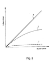
- the second electromagnetic clutch 12 via a second temperature sensor switched on, the fan blade 7 runs synchronously with the drive shaft 1, see Speed curve 3 in FIG. 2.
- the outer ring 8.3 of the second rolling bearing 8 to the radial part 10 of the Drive shaft 1 coupled and therefore runs at the same speed around.
- the second roller bearing 8 shown in an enlarged representation and in a modified form in FIG. 3 is designed as a three-ring bearing in the form of a double row inner angular contact ball bearing 8.6 and a double row outer angular contact ball bearing 8.7 in an O arrangement.
- the contact angle ⁇ 1 of the inner angular contact ball bearing 8.6 is greater than the contact angle ⁇ 2 of the associated outer angular contact ball bearing 8.7, so that the rigidity of the second roller bearing 8 is increased.
- All bearing rings 8.1, 8.2 and 8.3 are made in one piece.
- Each of the rows of balls 8.4 and 8.5 is guided in a separate cage 21, 22 and sealed to the outside by opposing seals 21, 22.
- the bearing rings 8.1, 8.2 and 8.3 are made of 100Cr6 and have a value of 58 + 6 HRC after hardening and tempering.
- the cages 21, 22 consist of a polyamide material.
- a drum was suspended in a chrome electrolyte containing 500 g / l chromium trioxide, 8 g / l methanesulfonic acid, 10 g / l magnesium silicon fluoride and 0.1 ml / l tetraethylammonium perfluorooctane sulfonate, into which a number of bearing balls made from a roller bearing steel were filled. These bearing balls were provided with a layer thickness of 0.7 ⁇ m at a current density of approximately 1.5 A / cm 2 .
- the operating temperature of the chrome electrolyte was around 40 °.
- the de r- bearing balls like provided with a layer of chromium were 3 used in the second rolling bearing 8 shown as a bearing ball rows 8.4 and installed in an electromagnetic fan clutch according to FIG. 1 It was shown that, in contrast to conventional bearing balls, a considerably longer lifespan of the fan arrangement could also be achieved in the case of impact-like loads and oscillating movements or vibrations with stationary rows of balls 8.4, 8.5 and rotating bearing rings 8.1, 8.2, 8.3.
Landscapes
- Engineering & Computer Science (AREA)
- General Engineering & Computer Science (AREA)
- Mechanical Engineering (AREA)
- Chemical & Material Sciences (AREA)
- Combustion & Propulsion (AREA)
- Physics & Mathematics (AREA)
- Electromagnetism (AREA)
- Rolling Contact Bearings (AREA)
- Structures Of Non-Positive Displacement Pumps (AREA)
- Magnetic Bearings And Hydrostatic Bearings (AREA)
- Wind Motors (AREA)
Abstract
Description
- Figur 1
- einen Längsschnitt durch eine elektromagnetische Lüfterkupplung nach dem bisherigen Stand der Technik;
- Figur 2
- eine grafische Darstellung der Abhängigkeit der Lüfterdrehzahl von der Drehzahl der Antriebswelle bei verschiedenen Schaltstufen und
- Figur 3
- ein erfindungsgemäßes Dreiring-Schrägkugellager zur Lüfterlagerung.
- 1
- Antriebswelle
- 2
- Gehäuse
- 3
- erstes Wälzlager
- 3.1
- Innenring
- 3.2
- Außenring
- 3.3
- Kugelreihe
- 4
- Achse
- 5
- Befestigungsschraube
- 6
- Riemenscheibe
- 7
- Lüfterrad
- 8
- zweites Wälzlager
- 8.1
- Innenring
- 8.2
- Zwischenring
- 8.3
- Außenring
- 8.4
- Kugelreihe
- 8.5
- Kugelreihe
- 8.6
- inneres Schrägkugellager
- 8.7
- äußeres Schrägkugellager
- 9
- Befestigungsschraube
- 10
- radialer Teil
- 10.1
- axialer Teil
- 11
- erste Elektromagnetkupplung
- 12
- zweite Elektromagnetkupplung
- 13
- Stromzuführung
- 14
- Stromzuführung
- 15
- Teil
- 16
- Teil
- 17
- Befestigungsschraube
- 18
- Befestigungsschraube
- 19
- Permanentmagnet
- 20
- Permanentmagnet
- 21
- Käfig
- 22
- Käfig
- 23
- Dichtung
- 24
- Dichtung
- α1,2
- Druckwinkel
Claims (11)
- Elektromagnetische Lüfterkupplung für eine Brennkraftmaschine mit einer in einem Gehäuse (2) über voneinander beabstandete erste Wälzlager (3) gehaltenen Antriebswelle (1), die an einem Ende über ein weiteres zweites Wälzlager (8) mit einem Lüfterrad (7) verbunden ist, wobei das zweite Wälzlager (8) als ein aus einem Innenring (8.1), einem Zwischenring (8.2) und einem Außenring (8.3) bestehendes Dreiringlager mit dazwischen angeordneten Wälzkörperreihen (8.4, 8.5) ausgebildet ist, dessen Innenring (8.1) fest mit der Antriebswelle (1), dessen Außenring (8.3) fest mit dem Lüfterrad (7) verbunden ist und dessen Zwischenring (8.2) über eine erste Elektromagnetkupplung (11) und dessen Außenring (8.3) über eine zweite Elektromagnetkupplung (12) mit der Antriebswelle (1) kuppelbar sind, dadurch gekennzeichnet, dass wenigstens im zweiten Wälzlager (8) unterschiedliche Werkstoffpaarungen beim Wälzkontakt vorhanden sind.
- Elektromagnetische Lüfterkupplung nach Anspruch 1, dadurch gekennzeichnet, dass wenigstens eine der zwischen Innenring (8.1) und Zwischenring (8.2) sowie Zwischenring (8.2) und Außenring (8.3) angeordneten Wälzkörperreihen (8.4,8.5) mit einer verschleißarmen Hartbeschichtung versehen ist.
- Elektromagnetische Lüfterkupplung nach Anspruch 1, dadurch gekennzeichnet, dass die Laufbahn des Innenringes (8.1) und die innere Laufbahn des Zwischenringes (8.2) mit einer verschleißarmen Hartbeschichtung versehen sind.
- Elektromagnetische Lüfterkupplung nach Anspruch 1, dadurch gekennzeichnet, dass die Laufbahn des Außenringes (8.3) und die äußere Laufbahn des Zwischenringes (8.2) mit einer verschleißarmen Hartbeschichtung versehen sind.
- Elektromagnetische Lüfterkupplung nach den Ansprüchen 1 bis 4, dadurch gekennzeichnet, dass die Beschichtung aus Chrom (Cr), Chromnitrid (CrN), Titannitrid (TiN), Titancarbonitrid (TiCN) oder aus Wolframcarbid/Kohlenstoff (WC/C) besteht.
- Elektromagnetische Lüfterkupplung nach Anspruch 5, dadurch gekennzeichnet, dass die Chromschicht eine Stärke von 0,01 bis 8,0 µm aufweist.
- Elektromagnetische Lüfterkupplung nach Anspruch 1, dadurch gekennzeichnet, dass die Beschichtung galvanisch, mittels PVD-Verfahren (Physical Vapour Deposition) oder mittels CVD-Verfahren (Chemical Vapour Deposition) erfolgt.
- Elektromagnetische Lüfterkupplung nach dem Oberbegriff von Anspruch 1, dadurch gekennzeichnet, dass wenigstens das zweite Wälzlager (8) mit einem Festschmierstoff befüllt ist, der gegebenenfalls von einer Trägersubstanz aufgenommen ist.
- Elektromagnetische Lüfterkupplung nach Anspruch 8, dadurch gekennzeichnet, dass die Trägersubstanz ein Lithiumseifenfett auf Mineralölbasis ist.
- Elektromagnetische Lüfterkupplung nach dem Oberbegriff von Anspruch 1, dadurch gekennzeichnet, dass wenigstens im zweiten Wälzlager (8) unterschiedliche Werkstoffpaarungen beim Wälzkontakt vorhanden sind und dieses mit einem Festschmierstoff befüllt ist, der gegebenenfalls von einer Trägersubstanz aufgenommen ist.
- Elektomagnetische Lüfterkupplung nach Anspruch 1, dadurch gekennzeichnet, dass das zweite Wälzlager (8) als Dreiringlager mit einem inneren und einem äußeren zweireihigen Schrägkugellager (8.6, 8.7) in O-Anordnung ausgebildet ist, wobei der Druckwinkel (α1) des inneren Lagers (8.6) größer als der Druckwinkel (α2) des äußeren Lagers (8.7) ist.
Applications Claiming Priority (2)
| Application Number | Priority Date | Filing Date | Title |
|---|---|---|---|
| DE10051985 | 2000-10-20 | ||
| DE10051985A DE10051985A1 (de) | 2000-10-20 | 2000-10-20 | Lüfterkupplung |
Publications (2)
| Publication Number | Publication Date |
|---|---|
| EP1199484A2 true EP1199484A2 (de) | 2002-04-24 |
| EP1199484A3 EP1199484A3 (de) | 2002-11-06 |
Family
ID=7660418
Family Applications (1)
| Application Number | Title | Priority Date | Filing Date |
|---|---|---|---|
| EP01122825A Withdrawn EP1199484A3 (de) | 2000-10-20 | 2001-09-22 | Dreiringwälzlager für Lüfterkupplung |
Country Status (5)
| Country | Link |
|---|---|
| US (1) | US6598720B2 (de) |
| EP (1) | EP1199484A3 (de) |
| JP (1) | JP2002147448A (de) |
| BR (1) | BR0104620A (de) |
| DE (1) | DE10051985A1 (de) |
Cited By (8)
| Publication number | Priority date | Publication date | Assignee | Title |
|---|---|---|---|---|
| DE102006027526B3 (de) * | 2006-06-14 | 2008-01-03 | Ab Skf | Anordnung |
| CN102635631A (zh) * | 2011-02-11 | 2012-08-15 | 罗伯特·博世有限公司 | 轴承 |
| CN102678258A (zh) * | 2012-05-29 | 2012-09-19 | 龙口市汽车风扇离合器厂 | 四速电磁风扇离合器 |
| WO2012168220A1 (de) * | 2011-06-09 | 2012-12-13 | Kendrion Linnig Gmbh | Elektromagnetisch betätigbare reibschaltkupplung |
| EP2387672A4 (de) * | 2009-01-15 | 2013-09-04 | Nsk Corp | Integriertes zweistufiges lager |
| US10054154B2 (en) * | 2011-04-19 | 2018-08-21 | Us Synthetic Corporation | Bearing apparatus including tilting pads |
| CN110500029A (zh) * | 2019-07-16 | 2019-11-26 | 中国石油天然气集团有限公司 | 一种tc轴承连接结构 |
| US11015647B2 (en) | 2017-09-08 | 2021-05-25 | Atlas Copco Airpower, Naamloze Vennootschap | Device provided with a bearing-in-bearing |
Families Citing this family (17)
| Publication number | Priority date | Publication date | Assignee | Title |
|---|---|---|---|---|
| DE10201405A1 (de) * | 2002-01-15 | 2003-07-24 | Siemens Ag | Pumpe |
| AT414006B (de) * | 2002-07-31 | 2006-08-15 | Knorr Bremse Gmbh | Türantrieb |
| JP2004190853A (ja) * | 2002-11-28 | 2004-07-08 | Usui Kokusai Sangyo Kaisha Ltd | マグネット式クラッチ装置 |
| US7211915B2 (en) * | 2003-10-15 | 2007-05-01 | Hewlett-Packard Development Company, L.P. | Motor assembly using redundant bearings and support elements |
| DE102005014347B4 (de) * | 2005-03-24 | 2009-06-18 | Linnig Trucktec Gmbh | Reibschaltkupplung |
| ITMI20051423A1 (it) * | 2005-07-22 | 2007-01-23 | Baruffaldi Spa | Dispositivo a doppia ancora per la trasmissione del moto a ventole di raffreddamento del motore di veicoli |
| ATE424503T1 (de) * | 2006-07-21 | 2009-03-15 | Linnig Trucktec Gmbh | Antriebsorgan für eine wasserpumpe |
| DE102008049618A1 (de) * | 2008-09-30 | 2010-04-01 | Kendrion Linnig Gmbh | Antriebseinheit und elektromagnetisch betätigbare Reibscheibenkupplung |
| EP2625439A1 (de) * | 2010-10-07 | 2013-08-14 | Carrier Corporation | Kupplungslager, elektromagnetische kupllung und transportkühleinheit |
| ITMI20111094A1 (it) * | 2011-06-17 | 2012-12-18 | Baruffaldi Spa | Dispositivo a doppio innesto per la trasmissione del moto a ventole di raffreddamento del motore di veicoli |
| CN102562252B (zh) * | 2012-01-11 | 2014-04-16 | 龙口中宇机械有限公司 | 电磁风扇离合器及其制造方法和控制方法 |
| DE102013209863A1 (de) * | 2013-05-28 | 2014-12-04 | Schaeffler Technologies Gmbh & Co. Kg | Beschichtetes Bauteil |
| CN103453047B (zh) * | 2013-08-16 | 2016-03-09 | 龙口澳雷樽传动机械有限公司 | 一种离合传动装置及其制造方法 |
| CN104153866B (zh) * | 2014-08-01 | 2015-05-13 | 刘淑芹 | 一种三速电磁硅油风扇离合器 |
| CN109424636B (zh) * | 2017-08-29 | 2020-12-29 | 中国航发商用航空发动机有限责任公司 | 多转子用轴承及航空发动机 |
| WO2020237580A1 (zh) * | 2019-05-30 | 2020-12-03 | 哈尔滨工业大学(深圳) | 旋转关节电磁锁紧装置及旋转关节 |
| EP3760539B1 (de) * | 2019-06-26 | 2021-09-29 | LEONARDO S.p.A. | Drehmomentausgleichsrotor für einen hubschrauber |
Family Cites Families (13)
| Publication number | Priority date | Publication date | Assignee | Title |
|---|---|---|---|---|
| AU457980B2 (en) * | 1970-11-18 | 1975-02-13 | Esso Research And Engineering Company | Lithium soap grease |
| US5067826A (en) * | 1987-03-31 | 1991-11-26 | Lemelson Jerome H | Ball and roller bearings and bearing components |
| US4871266A (en) * | 1987-06-24 | 1989-10-03 | Ngk Insulators, Ltd. | Slide assemblies |
| DE3739537A1 (de) * | 1987-11-21 | 1989-06-01 | Linnig Karl Heinz | Elektromagnetisch betaetigbare reibscheibenkupplung |
| DE4113526A1 (de) * | 1991-04-25 | 1992-10-29 | Zahnradfabrik Friedrichshafen | Waelzlager |
| US5165804A (en) * | 1991-09-03 | 1992-11-24 | General Electric Company | Rolling element bearing having wear resistant race land regions |
| US5593234A (en) * | 1995-05-16 | 1997-01-14 | Ntn Corporation | Bearing assembly with polycrystalline superlattice coating |
| DE19608672A1 (de) * | 1996-03-06 | 1997-09-11 | Skf Gmbh | Wälzlager für Rollen |
| SE514372C2 (sv) * | 1996-03-07 | 2001-02-19 | Skf Nova Ab | Smord rullningskontaktanordning, sätt och komposition för smörjning av en rullningskontaktanordning samt en keramisk rullkropp |
| US5731274A (en) * | 1996-09-11 | 1998-03-24 | Exxon Research And Engineering Company | Lithium complex grease with extended lubrication life |
| US6290398B1 (en) * | 1997-04-03 | 2001-09-18 | Koyo Seiko Co., Ltd. | Rolling bearing |
| SE9803957L (sv) * | 1998-11-18 | 2000-05-19 | Skf Nova Ab | Rullningslager med belagda komponenter |
| JP2002540354A (ja) * | 1999-03-23 | 2002-11-26 | ジェネラル・スキャンニング・インコーポレイテッド | 往復動用途のための長寿命の回転ボールベアリング及びその潤滑方法 |
-
2000
- 2000-10-20 DE DE10051985A patent/DE10051985A1/de not_active Ceased
-
2001
- 2001-09-22 EP EP01122825A patent/EP1199484A3/de not_active Withdrawn
- 2001-10-19 US US10/000,594 patent/US6598720B2/en not_active Expired - Fee Related
- 2001-10-19 BR BR0104620-9A patent/BR0104620A/pt not_active IP Right Cessation
- 2001-10-22 JP JP2001324090A patent/JP2002147448A/ja active Pending
Non-Patent Citations (1)
| Title |
|---|
| None |
Cited By (13)
| Publication number | Priority date | Publication date | Assignee | Title |
|---|---|---|---|---|
| DE102006027526B3 (de) * | 2006-06-14 | 2008-01-03 | Ab Skf | Anordnung |
| EP2387672A4 (de) * | 2009-01-15 | 2013-09-04 | Nsk Corp | Integriertes zweistufiges lager |
| CN102635631A (zh) * | 2011-02-11 | 2012-08-15 | 罗伯特·博世有限公司 | 轴承 |
| CN102635631B (zh) * | 2011-02-11 | 2015-11-25 | 罗伯特·博世有限公司 | 轴承 |
| US10570953B2 (en) | 2011-04-19 | 2020-02-25 | Us Synthetic Corporation | Bearing apparatus including tilting pads |
| US10054154B2 (en) * | 2011-04-19 | 2018-08-21 | Us Synthetic Corporation | Bearing apparatus including tilting pads |
| US11015646B2 (en) | 2011-04-19 | 2021-05-25 | US Synthetic Corportation | Bearing apparatus including tilting pads |
| WO2012168220A1 (de) * | 2011-06-09 | 2012-12-13 | Kendrion Linnig Gmbh | Elektromagnetisch betätigbare reibschaltkupplung |
| CN102678258B (zh) * | 2012-05-29 | 2014-11-05 | 龙口中宇汽车风扇离合器有限公司 | 四速电磁风扇离合器 |
| CN102678258A (zh) * | 2012-05-29 | 2012-09-19 | 龙口市汽车风扇离合器厂 | 四速电磁风扇离合器 |
| US11015647B2 (en) | 2017-09-08 | 2021-05-25 | Atlas Copco Airpower, Naamloze Vennootschap | Device provided with a bearing-in-bearing |
| EP3679258B1 (de) * | 2017-09-08 | 2022-02-23 | Atlas Copco Airpower, Naamloze Vennootschap | Vorrichtung mit einem lager im lager |
| CN110500029A (zh) * | 2019-07-16 | 2019-11-26 | 中国石油天然气集团有限公司 | 一种tc轴承连接结构 |
Also Published As
| Publication number | Publication date |
|---|---|
| US6598720B2 (en) | 2003-07-29 |
| US20020053496A1 (en) | 2002-05-09 |
| JP2002147448A (ja) | 2002-05-22 |
| EP1199484A3 (de) | 2002-11-06 |
| DE10051985A1 (de) | 2002-05-02 |
| BR0104620A (pt) | 2002-05-28 |
Similar Documents
| Publication | Publication Date | Title |
|---|---|---|
| EP1199484A2 (de) | Dreiringwälzlager für Lüfterkupplung | |
| DE4327815C2 (de) | Kugellager für einen Turbolader | |
| EP0288677B1 (de) | Bauteil, insbesondere Maschinenelement | |
| EP1972794B1 (de) | Vakuumpumpe | |
| DE102015201248B3 (de) | Gleitlageranordnung eines Drehelements auf einem Lagerbolzen, insbesondere eines Planetenrades auf einem Planetenradbolzen eines Planetenradgetriebes | |
| DE69937825T2 (de) | Beschichtetes wälzlager | |
| DE602005005428T2 (de) | Wälzlager eines Kipphebels | |
| EP2264217B1 (de) | Korrosionsfeste Beschichtung | |
| EP2324260A1 (de) | Gleitelement mit mehrfachschicht | |
| DE102013220063A1 (de) | Planetenradlageranordnung | |
| EP3524838B1 (de) | Abgedichtetes lagermodul | |
| WO2009135477A1 (de) | Käfig für wälzkörper eines lagers | |
| WO2009079979A1 (de) | Lageranordnung | |
| EP2600005B1 (de) | Vakuumpumpe mit einem käfiglosen Wälzlager | |
| AT510190A1 (de) | Verfahren zum herstellen eines mehrschichtigen gleitlagers | |
| KR101018182B1 (ko) | 릴리스 베어링 및 릴리스 베어링에 코팅을 도포하기 위한 방법 | |
| DE19982586B4 (de) | Wälzlager | |
| DE19651094A1 (de) | Tribosystem und Verfahren zu seiner Herstellung | |
| DE2825434B2 (de) | Rotationskolbenmaschine | |
| DE102006052869A1 (de) | PVD-Hartstoffbeschichtung von Kettengelenkteilen | |
| EP1522736A2 (de) | Lagerung für eine Rotorwelle eines elektromotorisch getriebenen Strömungsverdichters | |
| DE102008031730A1 (de) | Lagergehäuse und Abgasturbolader für eine Brennkraftmaschine | |
| KR20020042833A (ko) | 하이브리드 각 접촉형 볼 베어링 | |
| WO2008119322A1 (de) | Wälzlager mit festschmierstoff enthaltender lagerkomponente | |
| DE102006041717B4 (de) | Elektromechanische Lenkung |
Legal Events
| Date | Code | Title | Description |
|---|---|---|---|
| PUAI | Public reference made under article 153(3) epc to a published international application that has entered the european phase |
Free format text: ORIGINAL CODE: 0009012 |
|
| 17P | Request for examination filed |
Effective date: 20010922 |
|
| AK | Designated contracting states |
Kind code of ref document: A2 Designated state(s): AT BE CH CY DE DK ES FI FR GB GR IE IT LI LU MC NL PT SE TR |
|
| AX | Request for extension of the european patent |
Free format text: AL;LT;LV;MK;RO;SI |
|
| RAP1 | Party data changed (applicant data changed or rights of an application transferred) |
Owner name: INA-SCHAEFFLER KG |
|
| PUAL | Search report despatched |
Free format text: ORIGINAL CODE: 0009013 |
|
| AK | Designated contracting states |
Kind code of ref document: A3 Designated state(s): AT BE CH CY DE DK ES FI FR GB GR IE IT LI LU MC NL PT SE TR |
|
| AX | Request for extension of the european patent |
Free format text: AL;LT;LV;MK;RO;SI |
|
| RIC1 | Information provided on ipc code assigned before grant |
Free format text: 7F 16C 19/55 A, 7F 01P 7/08 B |
|
| AKX | Designation fees paid |
Designated state(s): DE ES FR GB IT |
|
| 17Q | First examination report despatched |
Effective date: 20050207 |
|
| STAA | Information on the status of an ep patent application or granted ep patent |
Free format text: STATUS: THE APPLICATION IS DEEMED TO BE WITHDRAWN |
|
| 18D | Application deemed to be withdrawn |
Effective date: 20050618 |