EP1199435A2 - Endstopfen zum Anschrauben von Sprossen an Abstandhalterrahmen von inbesondere Isolierglasscheiben - Google Patents
Endstopfen zum Anschrauben von Sprossen an Abstandhalterrahmen von inbesondere Isolierglasscheiben Download PDFInfo
- Publication number
- EP1199435A2 EP1199435A2 EP01107695A EP01107695A EP1199435A2 EP 1199435 A2 EP1199435 A2 EP 1199435A2 EP 01107695 A EP01107695 A EP 01107695A EP 01107695 A EP01107695 A EP 01107695A EP 1199435 A2 EP1199435 A2 EP 1199435A2
- Authority
- EP
- European Patent Office
- Prior art keywords
- plug
- longitudinal slot
- end plug
- plug according
- flange
- Prior art date
- Legal status (The legal status is an assumption and is not a legal conclusion. Google has not performed a legal analysis and makes no representation as to the accuracy of the status listed.)
- Granted
Links
- 125000006850 spacer group Chemical group 0.000 title claims abstract description 9
- 239000011521 glass Substances 0.000 claims abstract description 5
- 239000002699 waste material Substances 0.000 claims description 6
- 230000000149 penetrating effect Effects 0.000 claims description 3
- 230000007423 decrease Effects 0.000 claims 1
- 239000011796 hollow space material Substances 0.000 abstract 1
- 239000000463 material Substances 0.000 description 6
- 239000002184 metal Substances 0.000 description 2
- 238000010521 absorption reaction Methods 0.000 description 1
- 238000004873 anchoring Methods 0.000 description 1
- 230000009286 beneficial effect Effects 0.000 description 1
- 230000001427 coherent effect Effects 0.000 description 1
- 230000032258 transport Effects 0.000 description 1
Images
Classifications
-
- E—FIXED CONSTRUCTIONS
- E06—DOORS, WINDOWS, SHUTTERS, OR ROLLER BLINDS IN GENERAL; LADDERS
- E06B—FIXED OR MOVABLE CLOSURES FOR OPENINGS IN BUILDINGS, VEHICLES, FENCES OR LIKE ENCLOSURES IN GENERAL, e.g. DOORS, WINDOWS, BLINDS, GATES
- E06B3/00—Window sashes, door leaves, or like elements for closing wall or like openings; Layout of fixed or moving closures, e.g. windows in wall or like openings; Features of rigidly-mounted outer frames relating to the mounting of wing frames
- E06B3/66—Units comprising two or more parallel glass or like panes permanently secured together
- E06B3/663—Elements for spacing panes
- E06B3/667—Connectors therefor
- E06B3/6675—Connectors therefor for connection between the spacing elements and false glazing bars
-
- E—FIXED CONSTRUCTIONS
- E06—DOORS, WINDOWS, SHUTTERS, OR ROLLER BLINDS IN GENERAL; LADDERS
- E06B—FIXED OR MOVABLE CLOSURES FOR OPENINGS IN BUILDINGS, VEHICLES, FENCES OR LIKE ENCLOSURES IN GENERAL, e.g. DOORS, WINDOWS, BLINDS, GATES
- E06B3/00—Window sashes, door leaves, or like elements for closing wall or like openings; Layout of fixed or moving closures, e.g. windows in wall or like openings; Features of rigidly-mounted outer frames relating to the mounting of wing frames
- E06B3/66—Units comprising two or more parallel glass or like panes permanently secured together
- E06B3/663—Elements for spacing panes
- E06B3/667—Connectors therefor
-
- F—MECHANICAL ENGINEERING; LIGHTING; HEATING; WEAPONS; BLASTING
- F16—ENGINEERING ELEMENTS AND UNITS; GENERAL MEASURES FOR PRODUCING AND MAINTAINING EFFECTIVE FUNCTIONING OF MACHINES OR INSTALLATIONS; THERMAL INSULATION IN GENERAL
- F16B—DEVICES FOR FASTENING OR SECURING CONSTRUCTIONAL ELEMENTS OR MACHINE PARTS TOGETHER, e.g. NAILS, BOLTS, CIRCLIPS, CLAMPS, CLIPS OR WEDGES; JOINTS OR JOINTING
- F16B2200/00—Constructional details of connections not covered for in other groups of this subclass
- F16B2200/20—Connections with hook-like parts gripping behind a blind side of an element to be connected
- F16B2200/205—Connections with hook-like parts gripping behind a blind side of an element to be connected the hook being a separate retainer
-
- F—MECHANICAL ENGINEERING; LIGHTING; HEATING; WEAPONS; BLASTING
- F16—ENGINEERING ELEMENTS AND UNITS; GENERAL MEASURES FOR PRODUCING AND MAINTAINING EFFECTIVE FUNCTIONING OF MACHINES OR INSTALLATIONS; THERMAL INSULATION IN GENERAL
- F16B—DEVICES FOR FASTENING OR SECURING CONSTRUCTIONAL ELEMENTS OR MACHINE PARTS TOGETHER, e.g. NAILS, BOLTS, CIRCLIPS, CLAMPS, CLIPS OR WEDGES; JOINTS OR JOINTING
- F16B2200/00—Constructional details of connections not covered for in other groups of this subclass
- F16B2200/65—Miter joints
-
- Y—GENERAL TAGGING OF NEW TECHNOLOGICAL DEVELOPMENTS; GENERAL TAGGING OF CROSS-SECTIONAL TECHNOLOGIES SPANNING OVER SEVERAL SECTIONS OF THE IPC; TECHNICAL SUBJECTS COVERED BY FORMER USPC CROSS-REFERENCE ART COLLECTIONS [XRACs] AND DIGESTS
- Y10—TECHNICAL SUBJECTS COVERED BY FORMER USPC
- Y10T—TECHNICAL SUBJECTS COVERED BY FORMER US CLASSIFICATION
- Y10T403/00—Joints and connections
- Y10T403/46—Rod end to transverse side of member
- Y10T403/4602—Corner joint
-
- Y—GENERAL TAGGING OF NEW TECHNOLOGICAL DEVELOPMENTS; GENERAL TAGGING OF CROSS-SECTIONAL TECHNOLOGIES SPANNING OVER SEVERAL SECTIONS OF THE IPC; TECHNICAL SUBJECTS COVERED BY FORMER USPC CROSS-REFERENCE ART COLLECTIONS [XRACs] AND DIGESTS
- Y10—TECHNICAL SUBJECTS COVERED BY FORMER USPC
- Y10T—TECHNICAL SUBJECTS COVERED BY FORMER US CLASSIFICATION
- Y10T403/00—Joints and connections
- Y10T403/55—Member ends joined by inserted section
- Y10T403/559—Fluted or splined section
Definitions
- the invention relates to an end plug according to the preamble of claim 1.
- a rung cross connecting element is made from the utility model G 94 18 426 Plastic known for insulating glazing, through which arranged between two glass panes, intersecting hollow profile rungs, one of which is continuous and the other is divided into two, can be connected to each other in the intersection area, consisting of one two-piece connector in the cavity of the two-piece or cross bar, both of which Connector parts can be inserted into the crossbar parts and fastened to the longitudinal rung are, the two parts of the two-part connector having a longitudinal slot, in the an expanding wedge for expansion and thus for clamping the two Connector parts can be inserted in their cavities.
- the two point Connecting parts on a through hole extending in the axial direction, through which Screw can be inserted, which crosses the one-piece, continuous or longitudinal rung and by means of which the two connecting pieces can be screwed together and thereby on the Longitudinal rungs are attachable.
- the present invention has set itself the task of an end plug of the type mentioned to develop, which is particularly suitable for the attachment of rungs and cross bars or Grid bars in spacer frames of insulating glass panes are suitable if the connection between such rungs or cross bars and the frame by means of screws should, such connections, for example, within an automated Assembly line or to be made on special assembly frames and in particular on it care must be taken to prevent twisting of individual profiles when installed and where screw connections create a much more stable system, the opposite known connection systems considerable advantages in terms of handling and frame tightness offers.
- the plug body is assigned to Spread a longitudinal slot into which a screw penetrating the plug flange can be screwed in and expediently in the central longitudinal axis of the plug body lies and completely runs through the latter.
- the longitudinal slot can be of different widths, for example in its flange facing upper part of the plug body be wider than in its the plug end facing lower part.
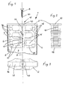
- the end plug 1 made of plastic shown in FIGS. 1-3 is used to screw on Rungs and cross bars on spacer frames, which are not shown in the drawing are, in particular of insulating glass panes.
- Fig. 1 the end is one Hollow profile rung 4 shown in longitudinal section, in the cavity 3 of the plug body 6 of the End plug is inserted, this plug body at one end with a Flange 2 is provided, which sits on the end face of the rung end and in this way prevents the end plug from sliding too far into the cavity 3 of the rung.
- the plug body 6 is in a known manner in cross section to the Cavity profile cross section of the rung 4 adapted and has for the purpose of Tolerance compensation on its outer circumference lamellar spring elements 16, which come on create the inside 5 of the hollow profile rung 4 and with it to a certain extent in frictional engagement Connect.
- the plug is provided with openings 15 and 17, the serve to save material.
- the end plug 1 designed to be spreadable.
- the longitudinal slot 7 has uneven surfaces or slot walls in the form of in Slot longitudinal direction of successive teeth 11, which are such that the Distance of the toothed, opposite diaphragm walls from the upper end of the plug at which there is the flange 2, downsized to the lower plug end 18 and beyond that Tip 10 of the screw 8 abuts the successive teeth 11 when screwing in and thereby widens the longitudinal slot 7, which means that in this embodiment of the End plug there is no line of sight between the two slot ends, but the View through the tips of the teeth 11 is blocked as long as the screw 8 is not is screwed in.
- the upper end of the longitudinal slot 7 has a recess 12 in the area of the flanges 2 Absorption of material chips, which arise from the fact that the screw 8 before it in the Flange 2 enters and thus the end plug 1 is fastened to the spacer frame the latter, which is usually made of metal, must pass through from the outside and thereby the screwing movement transports metal chips and splinters from the hole to the end plug.
- the recess 12 is of a feed cone 13 with a connected cylindrical Cavity 14 formed, the volumes of which are adapted to the expected amount of material waste are, which prevents the material chips and splinters between the surface of the flange 2 and the inside of the spacer frame and thereby one Prevent a coherent connection between the flange surface and the frame surface.
- the distance between the toothed, opposite walls of the Longitudinal slot 7 is selected in a proven embodiment so that this in the area of upper slot end is about 2 mm and 0.5 mm in the area of the lower slot end, and not in the installed state of the end plug, especially before the screw 8 in the End plug is screwed in to expand it.
Landscapes
- Engineering & Computer Science (AREA)
- Civil Engineering (AREA)
- Structural Engineering (AREA)
- Dowels (AREA)
- Building Environments (AREA)
- Connector Housings Or Holding Contact Members (AREA)
- Forms Removed On Construction Sites Or Auxiliary Members Thereof (AREA)
- Securing Of Glass Panes Or The Like (AREA)
Abstract
Description
- Fig. 1
- eine Vorderansicht des Endstopfens, eingebaut in ein axial aufgeschnittenes Sprossenprofil,
- Fig. 2
- eine Seitenansicht des Endstopfens von Fig. 1 und
- Fig. 3
- eine Draufsicht des Endstopfens von Fig. 1.
Claims (13)
- Endstopfen aus Kunststoff zum Anschrauben von Sprossen und Sprossenkreuzen an Abstandhalterrahmen von insbesondere Isolierglasscheiben, mit einem auf die Stirnseite der Sprosse aufzusetzenden Flansch und einem Stopfenkörper, der in den Profilkörperhohlraum der Hohlprofilsprosse hineinpasst und im Einbauzustand mit wenigstens einem Teil seiner Oberfläche mit der Innenwandoberaäche der Sprosse in Klemmberührung steht, dadurch gekennzeichnet, daß der Endstopfen (1) aufspreizbar ausgebildet ist.
- Endstopfen nach Anspruch 1, dadurch gekennzeichnet, daß der Stopfenkörper (6) zur Aufspreizung einen Längsschlitz (7) aufweist, in den eine den Flansch (2) durchgreifende Schraube (8) einschraubbar ist.
- Endstopfen nach Anspruch 2, dadurch gekennzeichnet, daß der Längsschlitz (7) in der mittigen Längsachse (9) des Stopfenkörpers (6) liegt.
- Endstopfen nach Anspruch 2 oder 3, dadurch gekennzeichnet, daß der Längsschlitz (7) den Stopfenkörper (6) vollständig durchzieht.
- Endstopfen nach einem der Ansprüche 2 - 4, dadurch gekennzeichnet, daß der Längsschlitz (7) zwischen den beiden Stopfenenden unterschiedlich breit ist.
- Endstopfen nach Anspruch 5, dadurch gekennzeichnet, daß der Längsschlitz (7) in seinem dem Flansch (2) zugewandten oberen Teil des Stopfenkörpers (6) breiter ist als in seinem dem Stopfenende (18) zugewandten unteren Teil.
- Endstopfen nach einem der Ansprüche 2 - 6, dadurch gekennzeichnet, daß der Längsschlitz (7) unebene Oberflächen bzw. Schlitzwände hat.
- Endstopfen nach Anspruch 7, dadurch gekennzeichnet, daß der Längsschlitz (7) verzahnt (11) ist.
- Endstopfen nach Anspruch 8, dadurch gekennzeichnet, daß der Abstand A der verzahnten gegenüberliegenden Längsschlitzwände sich vom oberen, den Flansch (2) aufweisenden Stopfenende zum unteren Stopfenende (18) hin verkleinert.
- Endstopfen nach einem der Ansprüche 7 - 9, dadurch gekennzeichnet, daß die Größe der Verzahnung so gewählt ist, daß die beim Anschrauben des Stopfens an den Abstandhalterrahmen durch den Schlitz (7) hindurchtretende Schraube (8) mit ihrer Spitze (10) gegen die aufeinanderfolgenden Zähne (11) stößt und dabei den Längsschlitz aufweitet.
- Endstopfen nach Anspruch 9 oder 10, dadurch gekennzeichnet, daß der Längsschlitz (7) in seinem oberen Bereich eine größere Weite (Abstand A) hat als im Bereich des unteren Stopfenendes (18).
- Endstopfen nach einem der Ansprüche 2 - 11, dadurch gekennzeichnet, daß das obere Ende des Längsschlitzes (7) im Bereich des Endstopfenansches (2) eine Vertiefung (12) zur Abfallmaterialaufnahme aufweist.
- Endstopfen nach Anspruch 12, dadurch gekennzeichnet, daß die Vertiefung (12) von einem Einzugskegel (13) mit angeschlossenem zylindrischen Hohlraum (14) gebildet ist, deren Volumina dem Abfallvolumen angepasst ist.
Applications Claiming Priority (2)
| Application Number | Priority Date | Filing Date | Title |
|---|---|---|---|
| DE20018012U DE20018012U1 (de) | 2000-10-20 | 2000-10-20 | Endstopfen zum Anschrauben von Sprossen an Abstandhalterrahmen von insbesondere Isolierglasscheiben |
| DE20018012U | 2000-10-20 |
Publications (3)
| Publication Number | Publication Date |
|---|---|
| EP1199435A2 true EP1199435A2 (de) | 2002-04-24 |
| EP1199435A3 EP1199435A3 (de) | 2003-01-15 |
| EP1199435B1 EP1199435B1 (de) | 2004-08-18 |
Family
ID=7947888
Family Applications (1)
| Application Number | Title | Priority Date | Filing Date |
|---|---|---|---|
| EP01107695A Expired - Lifetime EP1199435B1 (de) | 2000-10-20 | 2001-03-28 | Endstopfen zum Anschrauben von Sprossen an Abstandhalterrahmen von inbesondere Isolierglasscheiben |
Country Status (5)
| Country | Link |
|---|---|
| US (1) | US7104021B2 (de) |
| EP (1) | EP1199435B1 (de) |
| AT (1) | ATE274128T1 (de) |
| DE (2) | DE20018012U1 (de) |
| ES (1) | ES2225334T3 (de) |
Cited By (1)
| Publication number | Priority date | Publication date | Assignee | Title |
|---|---|---|---|---|
| EP1522668A3 (de) * | 2003-10-06 | 2006-07-05 | Poloplast GmbH | Verbinder für Doppelfenster-Rahmenprofile |
Families Citing this family (6)
| Publication number | Priority date | Publication date | Assignee | Title |
|---|---|---|---|---|
| DE20018012U1 (de) | 2000-10-20 | 2002-03-07 | R & R Sondermaschinen GmbH, 90579 Langenzenn | Endstopfen zum Anschrauben von Sprossen an Abstandhalterrahmen von insbesondere Isolierglasscheiben |
| AU2006275096B2 (en) * | 2005-08-01 | 2010-07-01 | Technoform Glass Insulation Holding Gmbh | Spacer arrangement with fusable connector for insulating glass units |
| US8001742B2 (en) * | 2006-08-16 | 2011-08-23 | Ged Integrated Solutions, Inc. | Muntin bar clip and muntin bar assembly |
| US7954284B2 (en) * | 2007-08-30 | 2011-06-07 | Ppg Industries Ohio, Inc. | Retainer clip for grid simulating muntins |
| US8307596B2 (en) * | 2009-09-21 | 2012-11-13 | Allmetal, Inc. | Key for connection of muntin or window pane spacer bars |
| US9387544B2 (en) | 2011-05-02 | 2016-07-12 | Fairfield Manufacturing Company, Inc. | Smilled spline apparatus and smilling process for manufacturing the smilled spline apparatus |
Citations (1)
| Publication number | Priority date | Publication date | Assignee | Title |
|---|---|---|---|---|
| DE9418426U1 (de) | 1994-11-17 | 1995-01-19 | Cera Handelsgesellschaft Mbh, 87640 Biessenhofen | Sprossenkreuzverbindungselement aus Kunststoff für Isolierverglasungen |
Family Cites Families (36)
| Publication number | Priority date | Publication date | Assignee | Title |
|---|---|---|---|---|
| US1052670A (en) * | 1912-01-31 | 1913-02-11 | Walter J La Francis | Building-veneer. |
| US1768157A (en) * | 1929-08-12 | 1930-06-24 | Walter Bates Steel Corp | Grating |
| US2181698A (en) * | 1938-09-29 | 1939-11-28 | Frederick G Langenberg | Wall construction |
| US2261510A (en) * | 1940-04-06 | 1941-11-04 | Atcheson James Edward | Double wall construction |
| US3293817A (en) * | 1964-09-28 | 1966-12-27 | Ams Corp | Muntin bars |
| US3766698A (en) * | 1971-08-23 | 1973-10-23 | Standard Products Co | Means for preventing panel roll out in a panel mounting system |
| US3785104A (en) * | 1971-11-15 | 1974-01-15 | Standard Products Co | Panel sealing system for internal glazing |
| US3932971A (en) * | 1973-05-21 | 1976-01-20 | Day Ralph K | Window construction |
| US3866380A (en) * | 1974-04-02 | 1975-02-18 | Warren Ind | Connector for window spacer assembly |
| US4120122A (en) * | 1977-08-23 | 1978-10-17 | Norman Bahr | Roof edge and wall cap and anchor |
| US4222209A (en) * | 1978-02-27 | 1980-09-16 | Peterson Metal Products, Ltd. | Cornerpiece for use in multiple pane window |
| US4628582A (en) * | 1981-12-04 | 1986-12-16 | Glass Equipment Development, Inc. | Method of making spacer frame for an insulating glass panel |
| US4530195A (en) * | 1980-04-03 | 1985-07-23 | Glass Equipment Development, Inc. | Spacer frame for an insulating glass panel and method of making the same |
| US4357744A (en) * | 1980-06-05 | 1982-11-09 | Mckenzie Everett R | Method of connecting insulated glass frame |
| US4418506A (en) * | 1980-09-02 | 1983-12-06 | Wausau Metals Corporation | Glazed wall construction system |
| US4683634A (en) * | 1985-10-18 | 1987-08-04 | Cole Richard D | Method of making an insulated window space assembly |
| US4707963A (en) * | 1986-06-26 | 1987-11-24 | Peachtree Doors, Inc. | Muntin assembly and method of installing |
| US5048997A (en) * | 1989-08-16 | 1991-09-17 | Alumet Mfg. Inc. | Flexible cornerpiece for spacer frame for insulated glass panel |
| DE9005886U1 (de) * | 1990-05-23 | 1990-07-26 | Cera Handelsgesellschaft Mbh, 8954 Biessenhofen | Kreuzverbinder aus Kunststoff für aus hohlen Aluminiumprofilstäben bestehende Fenstersprossen von Isolierglasscheiben |
| US5099626A (en) * | 1990-11-14 | 1992-03-31 | Allmetal Inc. | Connection for tubular muntin bars |
| KR930009114B1 (ko) * | 1991-04-22 | 1993-09-23 | 윤석규 | 분해 가능한 조립식 원목문 |
| US5313761A (en) * | 1992-01-29 | 1994-05-24 | Glass Equipment Development, Inc. | Insulating glass unit |
| GB9205192D0 (en) * | 1992-03-10 | 1992-04-22 | Emhart Inc | Universal plug |
| DE9204763U1 (de) * | 1992-04-07 | 1993-08-12 | Kronenberg, Hans Joachim, 42655 Solingen | Verbinder für Sprossenprofile |
| US5428924A (en) * | 1993-06-07 | 1995-07-04 | Pifer; George M. | High security window/door apparatus |
| KR970003388Y1 (ko) * | 1993-06-29 | 1997-04-16 | 윤석규 | 문틀 |
| DE4404630C2 (de) * | 1994-02-14 | 2002-11-21 | Werner Schmitz | Sprossen-T-Verbinder |
| DE9402404U1 (de) * | 1994-02-14 | 1994-04-07 | Schmitz, Werner, Dipl.-Ing., 37671 Höxter | Sprossen-Abstandshalter-Verbindung |
| DE19636220C2 (de) * | 1995-09-13 | 2001-02-08 | Lenhardt Maschinenbau | Isolierglasscheibe mit thermoplastischem Abstandhalter und mit eingesetztem Sprossenrahmen |
| US5678376A (en) * | 1995-10-30 | 1997-10-21 | Poma; James P. | Universal intercept clip |
| US5657590A (en) * | 1996-01-24 | 1997-08-19 | Quanex Corporation | Muntin bar assembly |
| US6164884A (en) * | 1998-08-17 | 2000-12-26 | Mayr; Alfred Friedrich | Anchor with spreading elements |
| US6244012B1 (en) * | 1999-01-20 | 2001-06-12 | Glass Equipment Development, Inc. | Muntin grid and joiner |
| WO2001012940A1 (en) * | 1999-08-13 | 2001-02-22 | Edgetech I.G., Inc. | Method of fabricating muntin bars for simulated divided lite windows |
| US6301843B1 (en) * | 2000-04-04 | 2001-10-16 | Silver Line Building Products Corp. | Muntin joint |
| DE20018012U1 (de) | 2000-10-20 | 2002-03-07 | R & R Sondermaschinen GmbH, 90579 Langenzenn | Endstopfen zum Anschrauben von Sprossen an Abstandhalterrahmen von insbesondere Isolierglasscheiben |
-
2000
- 2000-10-20 DE DE20018012U patent/DE20018012U1/de not_active Expired - Lifetime
-
2001
- 2001-03-28 DE DE50103298T patent/DE50103298D1/de not_active Expired - Lifetime
- 2001-03-28 EP EP01107695A patent/EP1199435B1/de not_active Expired - Lifetime
- 2001-03-28 ES ES01107695T patent/ES2225334T3/es not_active Expired - Lifetime
- 2001-03-28 AT AT01107695T patent/ATE274128T1/de active
- 2001-04-20 US US09/839,001 patent/US7104021B2/en not_active Expired - Fee Related
Patent Citations (1)
| Publication number | Priority date | Publication date | Assignee | Title |
|---|---|---|---|---|
| DE9418426U1 (de) | 1994-11-17 | 1995-01-19 | Cera Handelsgesellschaft Mbh, 87640 Biessenhofen | Sprossenkreuzverbindungselement aus Kunststoff für Isolierverglasungen |
Cited By (1)
| Publication number | Priority date | Publication date | Assignee | Title |
|---|---|---|---|---|
| EP1522668A3 (de) * | 2003-10-06 | 2006-07-05 | Poloplast GmbH | Verbinder für Doppelfenster-Rahmenprofile |
Also Published As
| Publication number | Publication date |
|---|---|
| ATE274128T1 (de) | 2004-09-15 |
| DE20018012U1 (de) | 2002-03-07 |
| ES2225334T3 (es) | 2005-03-16 |
| EP1199435A3 (de) | 2003-01-15 |
| US20020048486A1 (en) | 2002-04-25 |
| US7104021B2 (en) | 2006-09-12 |
| EP1199435B1 (de) | 2004-08-18 |
| DE50103298D1 (de) | 2004-09-23 |
Similar Documents
| Publication | Publication Date | Title |
|---|---|---|
| AT404219B (de) | Schublade | |
| DE2723850A1 (de) | Moebelscharnier | |
| EP1199435A2 (de) | Endstopfen zum Anschrauben von Sprossen an Abstandhalterrahmen von inbesondere Isolierglasscheiben | |
| DE7600101U1 (de) | Fester scharnierbeschlag | |
| DE2625181A1 (de) | Grund- bzw. verstellplatte fuer scharniere, insbesondere fuer moebelscharniere | |
| EP1522668B1 (de) | Verbinder für Doppelfenster-Rahmenprofile | |
| EP1035294B1 (de) | Kämpferverbinder-Satz | |
| DE3617198C2 (de) | ||
| DE9205273U1 (de) | Befestigungselement zur verdeckten Halterung | |
| DE2923903A1 (de) | Wandbefestigungselement fuer plattenheizkoerper | |
| DE1759497C3 (de) | Verbindungselement für die Herstellung einer Spannverbindung von Wandteilen oder anderen Teilen mit Profilschienen | |
| AT525006A1 (de) | Montageprofil | |
| EP0695849B1 (de) | Eckverbinder an Holmen von Fenstern, Türen od.dgl. | |
| CH687716A5 (de) | Beschlag. | |
| DE20310155U1 (de) | Schließplatte | |
| DE9016592U1 (de) | Geradverbinder, insbesondere aus Kunststoff, zur Verbindung von hohlen Abstandsprofilen und hohlen Sprossenprofilen eines Mehrscheibenisolierglases | |
| DE4013513C2 (de) | Steckverbinder für die geradlinige Stoßverbindung zweier Hohlprofile | |
| EP1491696A2 (de) | Profilverbindungssystem | |
| DE8913616U1 (de) | Abstandhalterahmen für Isolierverglasungen | |
| AT4995U1 (de) | Verbindungselement für trennwände zur facheinteilung einer schublade | |
| DE29516689U1 (de) | Bauelemente für Gestelle, Wandkonstruktionen o.dgl. | |
| DE8900359U1 (de) | Abstandhalterahmen für Isolierverglasungen | |
| DE29809330U1 (de) | Befestigungselement zum Aufhängen von Rahmen | |
| DE20019534U1 (de) | Verbinder | |
| EP0703342B1 (de) | Abstandshalterstopfen aus Kunststoff für profilierte Fenstersprossen von Isolierglasscheiben |
Legal Events
| Date | Code | Title | Description |
|---|---|---|---|
| PUAI | Public reference made under article 153(3) epc to a published international application that has entered the european phase |
Free format text: ORIGINAL CODE: 0009012 |
|
| AK | Designated contracting states |
Kind code of ref document: A2 Designated state(s): AT BE CH CY DE DK ES FI FR GB GR IE IT LI LU MC NL PT SE TR |
|
| AX | Request for extension of the european patent |
Free format text: AL;LT;LV;MK;RO;SI |
|
| PUAL | Search report despatched |
Free format text: ORIGINAL CODE: 0009013 |
|
| AK | Designated contracting states |
Kind code of ref document: A3 Designated state(s): AT BE CH CY DE DK ES FI FR GB GR IE IT LI LU MC NL PT SE TR |
|
| AX | Request for extension of the european patent |
Free format text: AL;LT;LV;MK;RO;SI |
|
| 17P | Request for examination filed |
Effective date: 20030618 |
|
| 17Q | First examination report despatched |
Effective date: 20030730 |
|
| AKX | Designation fees paid |
Designated state(s): AT BE CH CY DE DK ES FI FR GB GR IE IT LI LU MC NL PT SE TR |
|
| GRAP | Despatch of communication of intention to grant a patent |
Free format text: ORIGINAL CODE: EPIDOSNIGR1 |
|
| GRAS | Grant fee paid |
Free format text: ORIGINAL CODE: EPIDOSNIGR3 |
|
| GRAA | (expected) grant |
Free format text: ORIGINAL CODE: 0009210 |
|
| AK | Designated contracting states |
Kind code of ref document: B1 Designated state(s): AT BE CH CY DE DK ES FI FR GB GR IE IT LI LU MC NL PT SE TR |
|
| PG25 | Lapsed in a contracting state [announced via postgrant information from national office to epo] |
Ref country code: FI Free format text: LAPSE BECAUSE OF FAILURE TO SUBMIT A TRANSLATION OF THE DESCRIPTION OR TO PAY THE FEE WITHIN THE PRESCRIBED TIME-LIMIT Effective date: 20040818 Ref country code: TR Free format text: LAPSE BECAUSE OF FAILURE TO SUBMIT A TRANSLATION OF THE DESCRIPTION OR TO PAY THE FEE WITHIN THE PRESCRIBED TIME-LIMIT Effective date: 20040818 Ref country code: NL Free format text: LAPSE BECAUSE OF FAILURE TO SUBMIT A TRANSLATION OF THE DESCRIPTION OR TO PAY THE FEE WITHIN THE PRESCRIBED TIME-LIMIT Effective date: 20040818 Ref country code: IE Free format text: LAPSE BECAUSE OF FAILURE TO SUBMIT A TRANSLATION OF THE DESCRIPTION OR TO PAY THE FEE WITHIN THE PRESCRIBED TIME-LIMIT Effective date: 20040818 |
|
| REG | Reference to a national code |
Ref country code: GB Ref legal event code: FG4D Free format text: NOT ENGLISH |
|
| REG | Reference to a national code |
Ref country code: CH Ref legal event code: EP |
|
| REG | Reference to a national code |
Ref country code: IE Ref legal event code: FG4D Free format text: GERMAN |
|
| REF | Corresponds to: |
Ref document number: 50103298 Country of ref document: DE Date of ref document: 20040923 Kind code of ref document: P |
|
| REG | Reference to a national code |
Ref country code: CH Ref legal event code: NV Representative=s name: ABATRON-PATENTBUERO AG |
|
| PG25 | Lapsed in a contracting state [announced via postgrant information from national office to epo] |
Ref country code: DK Free format text: LAPSE BECAUSE OF FAILURE TO SUBMIT A TRANSLATION OF THE DESCRIPTION OR TO PAY THE FEE WITHIN THE PRESCRIBED TIME-LIMIT Effective date: 20041118 Ref country code: GR Free format text: LAPSE BECAUSE OF FAILURE TO SUBMIT A TRANSLATION OF THE DESCRIPTION OR TO PAY THE FEE WITHIN THE PRESCRIBED TIME-LIMIT Effective date: 20041118 Ref country code: SE Free format text: LAPSE BECAUSE OF FAILURE TO SUBMIT A TRANSLATION OF THE DESCRIPTION OR TO PAY THE FEE WITHIN THE PRESCRIBED TIME-LIMIT Effective date: 20041118 |
|
| GBT | Gb: translation of ep patent filed (gb section 77(6)(a)/1977) |
Effective date: 20041108 |
|
| NLV1 | Nl: lapsed or annulled due to failure to fulfill the requirements of art. 29p and 29m of the patents act | ||
| REG | Reference to a national code |
Ref country code: ES Ref legal event code: FG2A Ref document number: 2225334 Country of ref document: ES Kind code of ref document: T3 |
|
| REG | Reference to a national code |
Ref country code: IE Ref legal event code: FD4D |
|
| PG25 | Lapsed in a contracting state [announced via postgrant information from national office to epo] |
Ref country code: LU Free format text: LAPSE BECAUSE OF NON-PAYMENT OF DUE FEES Effective date: 20050328 Ref country code: CY Free format text: LAPSE BECAUSE OF FAILURE TO SUBMIT A TRANSLATION OF THE DESCRIPTION OR TO PAY THE FEE WITHIN THE PRESCRIBED TIME-LIMIT Effective date: 20050328 |
|
| PG25 | Lapsed in a contracting state [announced via postgrant information from national office to epo] |
Ref country code: BE Free format text: LAPSE BECAUSE OF NON-PAYMENT OF DUE FEES Effective date: 20050331 Ref country code: MC Free format text: LAPSE BECAUSE OF NON-PAYMENT OF DUE FEES Effective date: 20050331 |
|
| PLBE | No opposition filed within time limit |
Free format text: ORIGINAL CODE: 0009261 |
|
| STAA | Information on the status of an ep patent application or granted ep patent |
Free format text: STATUS: NO OPPOSITION FILED WITHIN TIME LIMIT |
|
| ET | Fr: translation filed | ||
| 26N | No opposition filed |
Effective date: 20050519 |
|
| BERE | Be: lapsed |
Owner name: *R & R SONDERMASCHINEN G.M.B.H. Effective date: 20050331 |
|
| PGFP | Annual fee paid to national office [announced via postgrant information from national office to epo] |
Ref country code: IT Payment date: 20060331 Year of fee payment: 6 |
|
| BERE | Be: lapsed |
Owner name: *R & R SONDERMASCHINEN G.M.B.H. Effective date: 20050331 |
|
| PG25 | Lapsed in a contracting state [announced via postgrant information from national office to epo] |
Ref country code: PT Free format text: LAPSE BECAUSE OF NON-PAYMENT OF DUE FEES Effective date: 20050118 |
|
| PG25 | Lapsed in a contracting state [announced via postgrant information from national office to epo] |
Ref country code: IT Free format text: LAPSE BECAUSE OF NON-PAYMENT OF DUE FEES Effective date: 20070328 |
|
| REG | Reference to a national code |
Ref country code: CH Ref legal event code: NV Representative=s name: 1A ABATRON PATENTBUERO |
|
| PGFP | Annual fee paid to national office [announced via postgrant information from national office to epo] |
Ref country code: CH Payment date: 20120326 Year of fee payment: 12 |
|
| PGFP | Annual fee paid to national office [announced via postgrant information from national office to epo] |
Ref country code: GB Payment date: 20120326 Year of fee payment: 12 |
|
| PGFP | Annual fee paid to national office [announced via postgrant information from national office to epo] |
Ref country code: AT Payment date: 20120321 Year of fee payment: 12 |
|
| PGFP | Annual fee paid to national office [announced via postgrant information from national office to epo] |
Ref country code: ES Payment date: 20120326 Year of fee payment: 12 |
|
| PGFP | Annual fee paid to national office [announced via postgrant information from national office to epo] |
Ref country code: DE Payment date: 20130529 Year of fee payment: 13 |
|
| REG | Reference to a national code |
Ref country code: CH Ref legal event code: PL |
|
| REG | Reference to a national code |
Ref country code: AT Ref legal event code: MM01 Ref document number: 274128 Country of ref document: AT Kind code of ref document: T Effective date: 20130328 |
|
| GBPC | Gb: european patent ceased through non-payment of renewal fee |
Effective date: 20130328 |
|
| PG25 | Lapsed in a contracting state [announced via postgrant information from national office to epo] |
Ref country code: LI Free format text: LAPSE BECAUSE OF NON-PAYMENT OF DUE FEES Effective date: 20130331 Ref country code: CH Free format text: LAPSE BECAUSE OF NON-PAYMENT OF DUE FEES Effective date: 20130331 Ref country code: GB Free format text: LAPSE BECAUSE OF NON-PAYMENT OF DUE FEES Effective date: 20130328 Ref country code: AT Free format text: LAPSE BECAUSE OF NON-PAYMENT OF DUE FEES Effective date: 20130328 |
|
| PGFP | Annual fee paid to national office [announced via postgrant information from national office to epo] |
Ref country code: FR Payment date: 20140317 Year of fee payment: 14 |
|
| REG | Reference to a national code |
Ref country code: ES Ref legal event code: FD2A Effective date: 20140716 |
|
| REG | Reference to a national code |
Ref country code: DE Ref legal event code: R119 Ref document number: 50103298 Country of ref document: DE |
|
| PG25 | Lapsed in a contracting state [announced via postgrant information from national office to epo] |
Ref country code: ES Free format text: LAPSE BECAUSE OF NON-PAYMENT OF DUE FEES Effective date: 20130329 |
|
| REG | Reference to a national code |
Ref country code: DE Ref legal event code: R119 Ref document number: 50103298 Country of ref document: DE Effective date: 20141001 |
|
| PG25 | Lapsed in a contracting state [announced via postgrant information from national office to epo] |
Ref country code: DE Free format text: LAPSE BECAUSE OF NON-PAYMENT OF DUE FEES Effective date: 20141001 |
|
| REG | Reference to a national code |
Ref country code: FR Ref legal event code: ST Effective date: 20151130 |
|
| PG25 | Lapsed in a contracting state [announced via postgrant information from national office to epo] |
Ref country code: FR Free format text: LAPSE BECAUSE OF NON-PAYMENT OF DUE FEES Effective date: 20150331 |