EP1198808B1 - Verfahren zur elektronischen antriebssteuerung - Google Patents
Verfahren zur elektronischen antriebssteuerung Download PDFInfo
- Publication number
- EP1198808B1 EP1198808B1 EP00951390A EP00951390A EP1198808B1 EP 1198808 B1 EP1198808 B1 EP 1198808B1 EP 00951390 A EP00951390 A EP 00951390A EP 00951390 A EP00951390 A EP 00951390A EP 1198808 B1 EP1198808 B1 EP 1198808B1
- Authority
- EP
- European Patent Office
- Prior art keywords
- value
- delay time
- instant
- supply voltage
- voltage
- Prior art date
- Legal status (The legal status is an assumption and is not a legal conclusion. Google has not performed a legal analysis and makes no representation as to the accuracy of the status listed.)
- Expired - Lifetime
Links
- 238000000034 method Methods 0.000 title claims abstract description 22
- 238000001514 detection method Methods 0.000 claims description 6
- 210000004027 cell Anatomy 0.000 claims 1
- 210000000352 storage cell Anatomy 0.000 claims 1
- 238000010586 diagram Methods 0.000 description 5
- 230000000694 effects Effects 0.000 description 4
- 230000001360 synchronised effect Effects 0.000 description 2
- 230000001419 dependent effect Effects 0.000 description 1
- 238000011161 development Methods 0.000 description 1
- 230000018109 developmental process Effects 0.000 description 1
Images

Classifications
-
- H—ELECTRICITY
- H01—ELECTRIC ELEMENTS
- H01H—ELECTRIC SWITCHES; RELAYS; SELECTORS; EMERGENCY PROTECTIVE DEVICES
- H01H9/00—Details of switching devices, not covered by groups H01H1/00 - H01H7/00
- H01H9/54—Circuit arrangements not adapted to a particular application of the switching device and for which no provision exists elsewhere
- H01H9/56—Circuit arrangements not adapted to a particular application of the switching device and for which no provision exists elsewhere for ensuring operation of the switch at a predetermined point in the AC cycle
- H01H9/563—Circuit arrangements not adapted to a particular application of the switching device and for which no provision exists elsewhere for ensuring operation of the switch at a predetermined point in the AC cycle for multipolar switches, e.g. different timing for different phases, selecting phase with first zero-crossing
Definitions
- the invention relates to a method for electronic drive control after The preamble of claim 1. Such a method is e.g. out US-A-5 530 615 is known.
- EP 0 789 378 A1 is an electronic drive control for a Magnetic drive known.
- control voltage of a contactor is derived from one of the three phases, it can be sync effects between the closing or opening angle of the Main contacts in the load circuit and the AC control voltage lead.
- the object of the invention is a method according to the preamble of claim 1 to create, in which the life of a contactor is increased.
- the invention prevents uneven burning of the switching contacts and thus increases the life of the contactor.
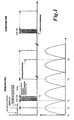
- Fig. 1 shows a timing diagram in which the rectified in a lower curve Supply voltage is shown, wherein the supply voltage a AC voltage is.
- a randomly determined delay time t x is provided, which lies between zero and half the period of the control voltage. Only after this delay time, wherein the time is marked with t 3 , the supply voltage is measured, wherein the supply voltage, both a DC and an AC voltage can be. It is checked which supply voltage is concerned (AC or DC). At the same time, the height of the applied voltage is determined. Furthermore, it is checked after t 3 whether the supply voltage is within a predetermined voltage window U min , U max , ie whether the determined value is within the permissible range.
- the switching point t 5 of the contacts is also distributed randomly for the other phases, which causes a uniform stress on the switching contacts.
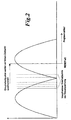
- the undesirable synchronization effect will be explained in more detail with reference to FIG.
- the dashed lines show different switch-on points, to which different voltage values can be assigned. Since the voltage for starting the microcontroller must first be established, the reset signal is almost always independent of the switch-on time on the same point of the curve, so that the switch-on times are practically synchronized to the same reset time. If the control voltage is switched on, for example, at zero voltage, the supply voltage for the electronics does not build up immediately.
- Random generator To realize a timer with a variable, randomly set time is Random generator needed.
- the value provided by the random number generator then becomes edited so that with the subsequent processing of the value a time of Zero to a maximum of half the period of the control voltage results.
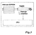
- FIG. 3 shows a schematic diagram.
- a value is read out in a RAM memory location in the microcontroller, wherein the content of this cell is not defined after power connection.
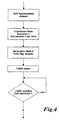
- 4 shows the associated flow chart for implementation with a RAM.
- a value is obtained from a memory cell 1 of an EEPROM, which is manipulated accordingly.
- the old value is used to determine the new value.
- the old value is then replaced by the new value in the EEPROM.
- the manipulated value is written in a register 2.
- the timer is then started. When the timer reaches zero, a timer underflow will be generated, which will be passed to the CPU, and the program will continue.
- Fig. 5 shows the corresponding flowchart.
Landscapes
- Engineering & Computer Science (AREA)
- Power Engineering (AREA)
- Relay Circuits (AREA)
- Control Of Electrical Variables (AREA)
- Hydraulic Clutches, Magnetic Clutches, Fluid Clutches, And Fluid Joints (AREA)
- Valve Device For Special Equipments (AREA)
- Control Of Motors That Do Not Use Commutators (AREA)
- Keying Circuit Devices (AREA)
- Electronic Switches (AREA)
- Control Of Eletrric Generators (AREA)
- Control Of Electric Motors In General (AREA)
Description
Wird die Steuerspannung im Spannungsnullpunkt zugeschaltet, so baut sich die Versorgungsspannung nicht sofort auf, sondern erst zu einem späterem Zeitpunkt. Im Bereich dieses Zeitpunktes erfolgt eine unerwünschte Synchronisation, die zur Folge hat, daß immer eines der drei Schaltkontakte des Schützes einem höheren Verschleiß unterliegt. Das heißt, daß ein Kontakt einen Einschaltpunkt aufweist, bei dem die Spannungshöhe unabhängig vom Zeitpunkt des Steuersignals annähernd gleich ist. Da die Lebensdauer des Schützes von der Lebensdauer des am meist abgebranntesten Kontaktes abhängt, tritt durch die Synchronisation eine Verkürzung der Lebensdauer des Gesamtgerätes ein.
- Fig. 1
- ein Zeitdiagramm,
- Fig. 2
- ein Diagramm ohne Verzögerungszeit,
- Fig. 3
- eine Prinzipdarstellung,
- Fig. 4
- ein erstes Flußdiagramm und
- Fig. 5
- ein weiteres Flußdiagramm.
Steht ein Pegel an, dann wird der konventionelle Betrieb erkannt.
Erst nach dieser Verzögerungszeit, wobei der Zeitpunkt mit t3 gekennzeichnet ist, wird die Versorgungsspannung gemessen, wobei die Versorgungsspannung, sowohl eine DC- als auch eine AC-Spannung sein kann. Dabei wird überprüft um welche Versorgungsspannung es sich handelt (AC oder DC). Gleichzeitig wird die Höhe der anliegenden Spannung ermittelt.
Weiterhin wird nach t3 geprüft, ob die Versorgungsspannung innerhalb eines vorgegebenen Spannungsfensters Umin, Umax liegt, d.h. ob der ermittelte Wert im zulässigen Bereich liegt.
Diese Vorgänge dauern etwa 12,5 ms an, wobei der Zeitpunkt t4, an dem der Schützantrieb aktiviert wird bzw. der Anzugvorgang eingeleitet wird, durch die Verzögerungszeit tx auf jedem beliebigen Punkt der Sinuskurve der Versorgungsspannung liegen kann. Die Zeit des Anzugvorgangs ist je nach Schutztyp verschieden.
Je nach Schütztyp erfolgt der Anzug nach 50 bis 100 ms.
Die gestrichelten Linien zeigen verschiedene Einschaltpunkte, denen unterschiedliche Spannungswerte zugeordnet sein können. Da die Spannung zum Starten des Microkontrollers erst aufgebaut werden muß, liegt das Resetsignal nahezu unabhängig vom Einschaltzeitpunkt stets auf dem gleichen Punkt der Kurve, so daß die Einschaltzeitpunkte praktisch auf den gleichen Resetzeitpunkt synchronisiert werden.
Wird die Steuerspannung z.B. im Spannungsnullzeitpunkt zugeschaltet, so baut sich die Versorgungsspannung für die Elektronik nicht sofort auf.
Fig. 3 zeigt eine Prinzipdarstellung.
Die Fig. 4 zeigt das zugehörigen Ablaufdiagramm zur Realisierung mit einem RAM.
Anschließend wird der manipulierte Wert in ein Register 2 geschrieben. Der Timer wird anschließend gestartet. Wenn der Timer den Wert Null erreicht, dann entsteht ein Timer underflow, der an die CPU weitergegeben wird, und das Programm wird fortgefahren.
Die Fig. 5 zeigt das entsprechende Flußdiagramm.
Claims (13)
- Verfahren zur elektronischen Antriebssteuerung einer Antriebspule eines Schützes mit Hauptkontakten für Laststrom und einer Elektronik, die einen Microkontroller aufweist, wobei eine per Zufall ausgewählte und ständig sich ändernde Verzögerungszeit (tx) vorhanden ist, dadurch gekennzeichnet, daß die Verzögerungszeit (tx) nach dem Zeitpunkt (t1, t2) liegt, an dem die Versorgungsspannung an der Elektronik aufgebaut ist und vor einem Zeitpunkt (t3) liegt, an dem die Versorgungsspannung gemessen ist.
- Verfahren nach Anspruch 1, dadurch gekennzeichnet, daß die Verzögerungszeit (tx) zwischen Null und der halben Periodendauer der Steuerspannung liegt.
- Verfahren nach einem der vorhergehenden Ansprüche, dadurch gekennzeichnet, daß zu einem vorgeordneten Zeitpunkt (t1), eine Erkennung, in welcher Ansteuerart der Schütz betrieben wird, erfolgt, wobei die Verzögerungszeit (tx) erst nach einem Zeitpunkt (t2) liegt, an dem die Erkennung beendet ist.
- Verfahren nach Anspruch 3, dadurch gekennzeichnet, daß sich die Erkennung auf einen konventionellen Betrieb, SPS-Betrieb oder leistungsarmen Betrieb bezieht.
- Verfahren nach Anspruch 4, dadurch gekennzeichnet, daß die Erkennung etwa 5 ms dauert.
- Verfahren nach einem der vorhergehenden Ansprüche, dadurch gekennzeichnet, daß nach der Verzögerungszeit (tx) zu einem nachfolgenden Zeitpunkt (t3) die Versorgungsspannung hinsichtlich AC- oder DC-Betrieb überprüft wird
- Verfahren nach einem der vorhergehenden Ansprüche, dadurch gekennzeichnet, daß nach der Verzögerungszeit (tx) zu einem nachfolgenden Zeitpunkt (t3) geprüft wird, ob die Versorgungsspannung innerhalb eines vorgegebenen Spannungsfensters (Umin, Umax) liegt.
- Verfahren nach einem der vorhergehenden Ansprüche, dadurch gekennzeichnet, daß zu einem späteren Zeitpunkt (t4), der nach etwa10 bis 15ms, vorzugsweise 12,5 ms liegt, der Schützantrieb aktiviert wird und der Anzugvorgang eingeleitet wird.
- Verfahren nach einem der vorhergehenden Ansprüche, dadurch gekennzeichnet, daß ein als Zufallsgenerator arbeitendes Zeitglied zur Realisierung der Verzögerungszeit, (tx) vorhanden ist, wobei der vom Zufallsgenerator gelieferte Wert anschließend so bearbeitet wird, daß sich mit der anschließenden Bearbeitung des Wertes eine Zeit von Null bis maximal der halben Periodendauer der Steuerspannung ergibt.
- Verfahren nach einem der vorhergehenden Ansprüche, dadurch gekennzeichnet, daß ein der Verzögerungszeit (tx) zuzuordnender Wert in einer RAM-Speicherstelle im Microkontroller ausgelesen wird, wobei der Inhalt dieser Zelle nach Spannungszuschaltung nicht definiert ist.
- Verfahren nach Anspruch 10, dadurch gekennzeichnet, daß anschließend der manipulierte Wert in ein Register als Timer geschrieben Wird., daß der Timer anschließend gestartet wird und daß, wenn der Timer den Wert Null erreicht, ein Timer-underflow entsteht, der an eine CPU weitergegeben wird, wobei dann ein Programm fortgefahren ' wird.
- Verfahren nach einem der vorhergehenden Ansprüche, dadurch gekennzeichnet, daß aus einer Speicherzelle (1) eines EEPROM ein Wert eingelesen wird, der manipuliert wird, wobei der alte Wert zur Ermittlung des neuen Wertes herangezogen wird und der alte Wert dann durch den neuen Wert im EEPROM ersetzt wird.
- Verfahren nach einem der vorhergehenden Ansprüche, dadurch gekennzeichnet, daß die Versorgungsspannung gemessen und geprüft wird.
Applications Claiming Priority (3)
| Application Number | Priority Date | Filing Date | Title |
|---|---|---|---|
| DE19935044 | 1999-07-26 | ||
| DE19935044A DE19935044A1 (de) | 1999-07-26 | 1999-07-26 | Verfahren zur elektronischen Antriebssteuerung |
| PCT/EP2000/006774 WO2001008181A1 (de) | 1999-07-26 | 2000-07-15 | Verfahren zur elektronischen antriebssteuerung |
Publications (2)
| Publication Number | Publication Date |
|---|---|
| EP1198808A1 EP1198808A1 (de) | 2002-04-24 |
| EP1198808B1 true EP1198808B1 (de) | 2003-10-01 |
Family
ID=7916099
Family Applications (1)
| Application Number | Title | Priority Date | Filing Date |
|---|---|---|---|
| EP00951390A Expired - Lifetime EP1198808B1 (de) | 1999-07-26 | 2000-07-15 | Verfahren zur elektronischen antriebssteuerung |
Country Status (8)
| Country | Link |
|---|---|
| US (1) | US6671157B1 (de) |
| EP (1) | EP1198808B1 (de) |
| JP (1) | JP2003505840A (de) |
| AT (1) | ATE251332T1 (de) |
| AU (1) | AU6434700A (de) |
| DE (2) | DE19935044A1 (de) |
| ES (1) | ES2208389T3 (de) |
| WO (1) | WO2001008181A1 (de) |
Cited By (2)
| Publication number | Priority date | Publication date | Assignee | Title |
|---|---|---|---|---|
| DE102005043895A1 (de) * | 2005-09-14 | 2007-03-15 | Siemens Ag | Verfahren zum Betreiben eines elektromechanisch betätigten Schaltgerätes und nach diesem Verfahren betriebenes Schaltgerät |
| DE102006014914B3 (de) * | 2006-03-30 | 2007-10-04 | Siemens Ag | Verfahren zum Betreiben eines elektromechanisch betätigten Schaltgerätes und nach diesem Verfahren betriebenes Schaltgerät |
Families Citing this family (2)
| Publication number | Priority date | Publication date | Assignee | Title |
|---|---|---|---|---|
| EP2856483B1 (de) | 2012-05-30 | 2016-07-13 | ABB Research Ltd. | Verfahren und vorrichtung zum umschalten eines schützes |
| EP3422382B1 (de) * | 2017-06-28 | 2020-03-25 | ABB Schweiz AG | Verfahren und steuerungsvorrichtung zum schalten eines schützes |
Family Cites Families (9)
| Publication number | Priority date | Publication date | Assignee | Title |
|---|---|---|---|---|
| DE3110314A1 (de) * | 1980-07-31 | 1982-04-01 | LGZ Landis & Gyr Zug AG, 6301 Zug | System und einrichtung zur betaetigung eines elektromagneten |
| JPS632219A (ja) * | 1986-06-20 | 1988-01-07 | 株式会社東芝 | リレ−駆動回路 |
| EP0571122B1 (de) | 1992-05-20 | 1998-08-12 | Texas Instruments Incorporated | Verfahren und Einrichtung zur Verlängerung der Lebensdauer eines Relais |
| US5377068A (en) * | 1992-10-19 | 1994-12-27 | Predator Systems Inc. | Electromagnet with holding control |
| US5442511A (en) * | 1993-03-30 | 1995-08-15 | Caterpillar Inc. | Generic solenoid driver circuit board, circuit and method of making same |
| US5914849A (en) * | 1994-04-26 | 1999-06-22 | Kilovac Corporation | DC actuator control circuit with voltage compensation, current control and fast dropout period |
| US5838077A (en) | 1995-07-12 | 1998-11-17 | Pittway Corporation | Control system for switching loads on zero crossing |
| SE505747C2 (sv) * | 1996-02-07 | 1997-10-06 | Asea Brown Boveri | Kontaktorutrustning |
| US6249418B1 (en) * | 1999-01-27 | 2001-06-19 | Gary Bergstrom | System for control of an electromagnetic actuator |
-
1999
- 1999-07-26 DE DE19935044A patent/DE19935044A1/de not_active Withdrawn
-
2000
- 2000-07-15 AU AU64347/00A patent/AU6434700A/en not_active Abandoned
- 2000-07-15 DE DE50003920T patent/DE50003920D1/de not_active Expired - Lifetime
- 2000-07-15 JP JP2001512602A patent/JP2003505840A/ja active Pending
- 2000-07-15 WO PCT/EP2000/006774 patent/WO2001008181A1/de not_active Ceased
- 2000-07-15 EP EP00951390A patent/EP1198808B1/de not_active Expired - Lifetime
- 2000-07-15 US US10/048,047 patent/US6671157B1/en not_active Expired - Lifetime
- 2000-07-15 AT AT00951390T patent/ATE251332T1/de active
- 2000-07-15 ES ES00951390T patent/ES2208389T3/es not_active Expired - Lifetime
Cited By (3)
| Publication number | Priority date | Publication date | Assignee | Title |
|---|---|---|---|---|
| DE102005043895A1 (de) * | 2005-09-14 | 2007-03-15 | Siemens Ag | Verfahren zum Betreiben eines elektromechanisch betätigten Schaltgerätes und nach diesem Verfahren betriebenes Schaltgerät |
| DE102005043895B4 (de) * | 2005-09-14 | 2007-07-26 | Siemens Ag | Verfahren zum Betreiben eines elektromechanisch betätigten Schaltgerätes und nach diesem Verfahren betriebenes Schaltgerät |
| DE102006014914B3 (de) * | 2006-03-30 | 2007-10-04 | Siemens Ag | Verfahren zum Betreiben eines elektromechanisch betätigten Schaltgerätes und nach diesem Verfahren betriebenes Schaltgerät |
Also Published As
| Publication number | Publication date |
|---|---|
| WO2001008181A1 (de) | 2001-02-01 |
| JP2003505840A (ja) | 2003-02-12 |
| DE50003920D1 (de) | 2003-11-06 |
| ATE251332T1 (de) | 2003-10-15 |
| AU6434700A (en) | 2001-02-13 |
| US6671157B1 (en) | 2003-12-30 |
| DE19935044A1 (de) | 2001-02-01 |
| EP1198808A1 (de) | 2002-04-24 |
| ES2208389T3 (es) | 2004-06-16 |
Similar Documents
| Publication | Publication Date | Title |
|---|---|---|
| DE19819265C1 (de) | Verfahren zum Parametrieren einer integrierten Schaltungsanordnung und integrierte Schaltungsanordnung hierfür | |
| DE60222550T2 (de) | Verfahren und vorrichtung zur laststeuerung einer elektrischen leistungsversorgung | |
| DE3743310C2 (de) | ||
| DE102016105747B4 (de) | Konzept zum Detektieren eines Entkoppelns eines ersten Steckerteils eines elektrischen Steckverbinders von einem zweiten Steckerteil des elektrischen Steckverbinders | |
| EP0381789B1 (de) | Verfahren und Vorrichtung zur Steuerung von ein- oder mehrphasigen Wechselstromstellern | |
| DE3708071A1 (de) | Energieversorgungsvorrichtung, insbesondere fuer eine gasentlandungsvorrichtung | |
| DE4325210A1 (de) | Vorrichtung zum Neustarten eines Umrichters zum Antreiben eines Synchronmotors nach vorübergehender Unterbrechung | |
| EP0575715B1 (de) | Verfahren und Vorrichtung zur Einschaltstromstoss-Vermeidung | |
| AT413916B (de) | Verfahren und vorrichtung zur erkennung und steuerung von elektronischen schaltnetzteilen oder konventionellen transformatoren, jeweils mit oder ohne ohmscher last, insbesondere von beleuchtungseinrichtungen | |
| EP2223427B1 (de) | Verfahren und vorrichtung zum betreiben eines elektrischen antriebs mit hilfe einer phasenanschnittssteuerung | |
| EP1327254B1 (de) | Verfahren und vorrichtung zur reduzierung des kontaktabbrandes eines schaltgerätes | |
| EP1198808A1 (de) | Verfahren zur elektronischen antriebssteuerung | |
| EP0466738B1 (de) | Vorrichtung zur wechselstrom-einschaltbegrenzung | |
| EP1529335B1 (de) | Vorrichtung zur leistungssteuerung durch phasenanschnitt und verfahren zur verringerung von oberwellen | |
| DE69211783T2 (de) | Stromversorgung für elektrische Entladungsmachine | |
| DE69111187T2 (de) | Funkenerosionsbearbeitungssteuereinheit. | |
| DE10334478B4 (de) | Verfahren und Vorrichtung zum Widerstandsschweißen | |
| EP0458794B1 (de) | Verfahren und vorrichtung zur steuerung von ein- oder mehrphasigen wechselstromstellern | |
| CH686415A5 (de) | Elektrischer Funkenerosionsapparat. | |
| EP0931377B1 (de) | Drehstromsteller mit interruptgesteuerter phasenanschnittsteuerung | |
| DE69022302T2 (de) | Überwachungsvorrichtung für eine Maschine. | |
| DE2907478A1 (de) | Verfahren und vorrichtung zur steuerung elektrischer ventile in einem wechselstromnetz | |
| EP1351267B1 (de) | Verfahren fur ein netzsynchrones Schalten von Leistungsschaltern und Vorrichtung zur Durchfuhrung dieses Verfahrens | |
| EP2153700B1 (de) | Verfahren zur zündung und zum start von hochdruckentladungslampen | |
| EP1109177B1 (de) | Verfahren zum Schalten einer Last |
Legal Events
| Date | Code | Title | Description |
|---|---|---|---|
| PUAI | Public reference made under article 153(3) epc to a published international application that has entered the european phase |
Free format text: ORIGINAL CODE: 0009012 |
|
| 17P | Request for examination filed |
Effective date: 20011122 |
|
| AK | Designated contracting states |
Kind code of ref document: A1 Designated state(s): AT BE CH CY DE DK ES FI FR GB GR IE IT LI LU MC NL PT SE |
|
| AX | Request for extension of the european patent |
Free format text: AL;LT;LV;MK;RO;SI |
|
| GRAH | Despatch of communication of intention to grant a patent |
Free format text: ORIGINAL CODE: EPIDOS IGRA |
|
| GRAH | Despatch of communication of intention to grant a patent |
Free format text: ORIGINAL CODE: EPIDOS IGRA |
|
| GRAA | (expected) grant |
Free format text: ORIGINAL CODE: 0009210 |
|
| AK | Designated contracting states |
Kind code of ref document: B1 Designated state(s): AT BE CH CY DE DK ES FI FR GB GR IE IT LI LU MC NL PT SE |
|
| PG25 | Lapsed in a contracting state [announced via postgrant information from national office to epo] |
Ref country code: FI Free format text: LAPSE BECAUSE OF FAILURE TO SUBMIT A TRANSLATION OF THE DESCRIPTION OR TO PAY THE FEE WITHIN THE PRESCRIBED TIME-LIMIT Effective date: 20031001 Ref country code: IE Free format text: LAPSE BECAUSE OF FAILURE TO SUBMIT A TRANSLATION OF THE DESCRIPTION OR TO PAY THE FEE WITHIN THE PRESCRIBED TIME-LIMIT Effective date: 20031001 Ref country code: CY Free format text: LAPSE BECAUSE OF FAILURE TO SUBMIT A TRANSLATION OF THE DESCRIPTION OR TO PAY THE FEE WITHIN THE PRESCRIBED TIME-LIMIT Effective date: 20031001 |
|
| REG | Reference to a national code |
Ref country code: GB Ref legal event code: FG4D Free format text: NOT ENGLISH |
|
| REG | Reference to a national code |
Ref country code: CH Ref legal event code: EP |
|
| REG | Reference to a national code |
Ref country code: IE Ref legal event code: FG4D Free format text: GERMAN |
|
| REF | Corresponds to: |
Ref document number: 50003920 Country of ref document: DE Date of ref document: 20031106 Kind code of ref document: P |
|
| REG | Reference to a national code |
Ref country code: CH Ref legal event code: NV Representative=s name: E. BLUM & CO. PATENTANWAELTE |
|
| PG25 | Lapsed in a contracting state [announced via postgrant information from national office to epo] |
Ref country code: GR Free format text: LAPSE BECAUSE OF FAILURE TO SUBMIT A TRANSLATION OF THE DESCRIPTION OR TO PAY THE FEE WITHIN THE PRESCRIBED TIME-LIMIT Effective date: 20040101 Ref country code: DK Free format text: LAPSE BECAUSE OF FAILURE TO SUBMIT A TRANSLATION OF THE DESCRIPTION OR TO PAY THE FEE WITHIN THE PRESCRIBED TIME-LIMIT Effective date: 20040101 |
|
| REG | Reference to a national code |
Ref country code: SE Ref legal event code: TRGR |
|
| GBT | Gb: translation of ep patent filed (gb section 77(6)(a)/1977) |
Effective date: 20040122 |
|
| LTIE | Lt: invalidation of european patent or patent extension |
Effective date: 20031001 |
|
| REG | Reference to a national code |
Ref country code: ES Ref legal event code: FG2A Ref document number: 2208389 Country of ref document: ES Kind code of ref document: T3 |
|
| REG | Reference to a national code |
Ref country code: IE Ref legal event code: FD4D |
|
| PG25 | Lapsed in a contracting state [announced via postgrant information from national office to epo] |
Ref country code: LU Free format text: LAPSE BECAUSE OF NON-PAYMENT OF DUE FEES Effective date: 20040715 |
|
| ET | Fr: translation filed | ||
| PG25 | Lapsed in a contracting state [announced via postgrant information from national office to epo] |
Ref country code: MC Free format text: LAPSE BECAUSE OF NON-PAYMENT OF DUE FEES Effective date: 20040731 |
|
| PLBE | No opposition filed within time limit |
Free format text: ORIGINAL CODE: 0009261 |
|
| STAA | Information on the status of an ep patent application or granted ep patent |
Free format text: STATUS: NO OPPOSITION FILED WITHIN TIME LIMIT |
|
| 26N | No opposition filed |
Effective date: 20040702 |
|
| REG | Reference to a national code |
Ref country code: CH Ref legal event code: PFA Owner name: MOELLER GMBH Free format text: MOELLER GMBH#HEIN-MOELLER-STRASSE 7-11#53115 BONN (DE) -TRANSFER TO- MOELLER GMBH#HEIN-MOELLER-STRASSE 7-11#53115 BONN (DE) |
|
| PG25 | Lapsed in a contracting state [announced via postgrant information from national office to epo] |
Ref country code: PT Free format text: LAPSE BECAUSE OF NON-PAYMENT OF DUE FEES Effective date: 20040301 |
|
| PGFP | Annual fee paid to national office [announced via postgrant information from national office to epo] |
Ref country code: BE Payment date: 20130722 Year of fee payment: 14 Ref country code: AT Payment date: 20130624 Year of fee payment: 14 Ref country code: CH Payment date: 20130806 Year of fee payment: 14 Ref country code: SE Payment date: 20130708 Year of fee payment: 14 Ref country code: ES Payment date: 20130705 Year of fee payment: 14 |
|
| REG | Reference to a national code |
Ref country code: CH Ref legal event code: PL |
|
| REG | Reference to a national code |
Ref country code: SE Ref legal event code: EUG |
|
| REG | Reference to a national code |
Ref country code: AT Ref legal event code: MM01 Ref document number: 251332 Country of ref document: AT Kind code of ref document: T Effective date: 20140715 |
|
| PG25 | Lapsed in a contracting state [announced via postgrant information from national office to epo] |
Ref country code: LI Free format text: LAPSE BECAUSE OF NON-PAYMENT OF DUE FEES Effective date: 20140731 Ref country code: CH Free format text: LAPSE BECAUSE OF NON-PAYMENT OF DUE FEES Effective date: 20140731 |
|
| PG25 | Lapsed in a contracting state [announced via postgrant information from national office to epo] |
Ref country code: SE Free format text: LAPSE BECAUSE OF NON-PAYMENT OF DUE FEES Effective date: 20140716 Ref country code: AT Free format text: LAPSE BECAUSE OF NON-PAYMENT OF DUE FEES Effective date: 20140715 |
|
| REG | Reference to a national code |
Ref country code: FR Ref legal event code: PLFP Year of fee payment: 16 |
|
| REG | Reference to a national code |
Ref country code: ES Ref legal event code: FD2A Effective date: 20150828 |
|
| PG25 | Lapsed in a contracting state [announced via postgrant information from national office to epo] |
Ref country code: ES Free format text: LAPSE BECAUSE OF NON-PAYMENT OF DUE FEES Effective date: 20140716 |
|
| REG | Reference to a national code |
Ref country code: FR Ref legal event code: PLFP Year of fee payment: 17 |
|
| REG | Reference to a national code |
Ref country code: FR Ref legal event code: PLFP Year of fee payment: 18 |
|
| PG25 | Lapsed in a contracting state [announced via postgrant information from national office to epo] |
Ref country code: BE Free format text: LAPSE BECAUSE OF NON-PAYMENT OF DUE FEES Effective date: 20140731 |
|
| REG | Reference to a national code |
Ref country code: FR Ref legal event code: PLFP Year of fee payment: 19 |
|
| PGFP | Annual fee paid to national office [announced via postgrant information from national office to epo] |
Ref country code: IT Payment date: 20190624 Year of fee payment: 20 Ref country code: NL Payment date: 20190625 Year of fee payment: 20 |
|
| PGFP | Annual fee paid to national office [announced via postgrant information from national office to epo] |
Ref country code: FR Payment date: 20190621 Year of fee payment: 20 |
|
| PGFP | Annual fee paid to national office [announced via postgrant information from national office to epo] |
Ref country code: GB Payment date: 20190624 Year of fee payment: 20 Ref country code: DE Payment date: 20190620 Year of fee payment: 20 |
|
| REG | Reference to a national code |
Ref country code: GB Ref legal event code: PE20 Expiry date: 20200714 |
|
| REG | Reference to a national code |
Ref country code: NL Ref legal event code: MK Effective date: 20200714 |
|
| PG25 | Lapsed in a contracting state [announced via postgrant information from national office to epo] |
Ref country code: GB Free format text: LAPSE BECAUSE OF EXPIRATION OF PROTECTION Effective date: 20200714 |