EP1197426A1 - Automatic accident reporting apparatus for two-wheeled vehicles - Google Patents
Automatic accident reporting apparatus for two-wheeled vehicles Download PDFInfo
- Publication number
- EP1197426A1 EP1197426A1 EP01930016A EP01930016A EP1197426A1 EP 1197426 A1 EP1197426 A1 EP 1197426A1 EP 01930016 A EP01930016 A EP 01930016A EP 01930016 A EP01930016 A EP 01930016A EP 1197426 A1 EP1197426 A1 EP 1197426A1
- Authority
- EP
- European Patent Office
- Prior art keywords
- accident
- vehicle
- informing
- acceleration
- detecting
- Prior art date
- Legal status (The legal status is an assumption and is not a legal conclusion. Google has not performed a legal analysis and makes no representation as to the accuracy of the status listed.)
- Granted
Links
Images




Classifications
-
- B—PERFORMING OPERATIONS; TRANSPORTING
- B62—LAND VEHICLES FOR TRAVELLING OTHERWISE THAN ON RAILS
- B62J—CYCLE SADDLES OR SEATS; AUXILIARY DEVICES OR ACCESSORIES SPECIALLY ADAPTED TO CYCLES AND NOT OTHERWISE PROVIDED FOR, e.g. ARTICLE CARRIERS OR CYCLE PROTECTORS
- B62J27/00—Safety equipment
-
- B—PERFORMING OPERATIONS; TRANSPORTING
- B62—LAND VEHICLES FOR TRAVELLING OTHERWISE THAN ON RAILS
- B62J—CYCLE SADDLES OR SEATS; AUXILIARY DEVICES OR ACCESSORIES SPECIALLY ADAPTED TO CYCLES AND NOT OTHERWISE PROVIDED FOR, e.g. ARTICLE CARRIERS OR CYCLE PROTECTORS
- B62J43/00—Arrangements of batteries
- B62J43/30—Arrangements of batteries for providing power to equipment other than for propulsion
-
- B—PERFORMING OPERATIONS; TRANSPORTING
- B62—LAND VEHICLES FOR TRAVELLING OTHERWISE THAN ON RAILS
- B62J—CYCLE SADDLES OR SEATS; AUXILIARY DEVICES OR ACCESSORIES SPECIALLY ADAPTED TO CYCLES AND NOT OTHERWISE PROVIDED FOR, e.g. ARTICLE CARRIERS OR CYCLE PROTECTORS
- B62J45/00—Electrical equipment arrangements specially adapted for use as accessories on cycles, not otherwise provided for
- B62J45/20—Cycle computers as cycle accessories
-
- B—PERFORMING OPERATIONS; TRANSPORTING
- B62—LAND VEHICLES FOR TRAVELLING OTHERWISE THAN ON RAILS
- B62J—CYCLE SADDLES OR SEATS; AUXILIARY DEVICES OR ACCESSORIES SPECIALLY ADAPTED TO CYCLES AND NOT OTHERWISE PROVIDED FOR, e.g. ARTICLE CARRIERS OR CYCLE PROTECTORS
- B62J50/00—Arrangements specially adapted for use on cycles not provided for in main groups B62J1/00 - B62J45/00
- B62J50/20—Information-providing devices
-
- B—PERFORMING OPERATIONS; TRANSPORTING
- B62—LAND VEHICLES FOR TRAVELLING OTHERWISE THAN ON RAILS
- B62J—CYCLE SADDLES OR SEATS; AUXILIARY DEVICES OR ACCESSORIES SPECIALLY ADAPTED TO CYCLES AND NOT OTHERWISE PROVIDED FOR, e.g. ARTICLE CARRIERS OR CYCLE PROTECTORS
- B62J50/00—Arrangements specially adapted for use on cycles not provided for in main groups B62J1/00 - B62J45/00
- B62J50/20—Information-providing devices
- B62J50/21—Information-providing devices intended to provide information to rider or passenger
- B62J50/22—Information-providing devices intended to provide information to rider or passenger electronic, e.g. displays
-
- G—PHYSICS
- G08—SIGNALLING
- G08B—SIGNALLING SYSTEMS, e.g. PERSONAL CALLING SYSTEMS; ORDER TELEGRAPHS; ALARM SYSTEMS
- G08B25/00—Alarm systems in which the location of the alarm condition is signalled to a central station, e.g. fire or police telegraphic systems
- G08B25/01—Alarm systems in which the location of the alarm condition is signalled to a central station, e.g. fire or police telegraphic systems characterised by the transmission medium
- G08B25/016—Personal emergency signalling and security systems
Definitions
- the present invention relates to a automatic accident informing apparatus for a two-wheel vehicle and particularly to an accident informing apparatus for detecting the accident of a two-wheel vehicle with the use of a simple arrangement but not an acceleration sensor and automatically informing of the accident.
- the accident is detected by an acceleration sensor mounted a vehicle when a significant degree of acceleration is sensed and an emergency signal is transmitted together with data of the position of the vehicle by a radio communicating means to a predetermined station.
- the acceleration sensors provided for an air-bag safety system are used as accident sensors for detecting the accident, the number of components and the overall weight will be decreased, thus minimizing the cost of the apparatus.
- the prior arts are however developed for four-wheel vehicles and can hardly be applied to two-wheel vehicles. Because the existing two-wheel vehicles are commonly provided with no air-bag safety system, the acceleration sensors have to be mounted separately. Additionally, the accident of the two-wheel vehicles includes not only a crash but also a fall down. The level of acceleration at the fall down may be smaller than that at the crash. It is hence difficult to determine whether the accident is a crash or a fall down with the use of a single acceleration sensor. As a result, either different sensing range types or an advanced, expensive, wider sensing range type of the acceleration sensor have to be used.
- an automatic accident informing apparatus for a two-wheel vehicle which includes an accident detecting means for detecting an accident of the vehicle and an accident informing means for informing an external party(s) of the accident is adapted having the following features according to the present invention.
- Fig. 1 is a block diagram of an automatic accident informing apparatus for a two-wheel vehicle according to one embodiment of the present invention, which comprises a vehicle speed sensor 1 for generating a signal indicative of the speed of a vehicle, an inclination sensor 2 for generating a signal indicative of the angle of inclination of the vehicle, an accident detecting module 3 for detecting an accident of the vehicle, an accident informing module 7 responsive to the detection of the accident in the accident detecting module 3 for informing an external party of the accident, and a drive recorder 8 for recording driving data before and after the accident.
- a vehicle speed sensor 1 for generating a signal indicative of the speed of a vehicle
- an inclination sensor 2 for generating a signal indicative of the angle of inclination of the vehicle
- an accident detecting module 3 for detecting an accident of the vehicle
- an accident informing module 7 responsive to the detection of the accident in the accident detecting module 3 for informing an external party of the accident
- a drive recorder 8 for recording driving data before and after the accident.
- the accident detecting module 3 includes a detector 31 for detecting the inclination angle ⁇ and the speed V of the vehicle from the output signals of the vehicle speed sensor 1 and the inclination sensor 2, a GPS unit 32, an antenna unit 33 connected to the GPS unit 32, and a main CPU 34.
- the GPS unit 32 measures the latitude Lat, the longitude Lon, the direction Dir, and the speed Vgps of the vehicle.
- the main CPU 34 includes a vehicle speed history memory 343 for saving a history of the vehicle speed V measured by the vehicle speed sensor 1, an acceleration calculator 342 for calculating the acceleration dV of the vehicle from data saved in the vehicle speed history memory 343, a line break detector 341 for examining whether or not the signal line L1 from the vehicle speed sensor 1, the signal line L2 from the inclination sensor 2, and the signal line L3 from the GPS antenna 33 are broken, and an accident judgment 340 for judging from the speed V, the inclination angle ⁇ , the acceleration dV of the vehicle, and a signal output of the line break detector 341 whether the vehicle has an accident or not.
- the signal lines L1 and L2 of the detector 31 side and the signal line L3 of the GPS unit 32 side are pulled down (or up) with high resistances.
- the line break detector 341 constantly monitors the voltage level on the signal lines L1, L2, and L3 and when the voltage level is turned to "L" (or "H") level, detects break in line.
- the main CPU 34 is also connected with an emergency switch 4, a rest switch 5, and a display 6.
- the emergency switch 4 is switched on by a driver informing of an accident regardless of the actual event.
- the reset switch 5 is also switched on when no information is needed. Upon receiving a reset signal from the reset switch 5, the main CPU 34 (and/or the accident informing module 7) cancels the action of information.
- the accident informing module 7 includes an accident data memory 71 and a communications device 72.
- the accident data memory 71 has an informed party area 71a for saving at least one party to be informed and a position data area 71b for saving the position of the vehicle at the time of the accident received from the GPS unit 32.
- the communications device 72 upon receiving a command of informing the accident from the CPU 34 transmits by radio the position data together with a message of the accident to all the parties saved in the informed party area 71a.
- the main CPU 34 and the accident informing module 7 are also energized with a backup battery 10 for continuing the transmission of the accident message when a main battery 9 or breaks the power line Lb is broken by the accident.
- the antenna 73 for the communications device 72 may be built in the accident informing module 7 or installed together with the accident informing module 7 in a single enclosure. As its signal line is not exposed to the outside, the antenna 73 will hardly lose its function by the accident.
- the accident detecting module 3 and the accident informing module 7 may be connected to a radio communications network by the Bluetooth standard which has been developed for near-distant data communications.
- the Bluetooth standard which has been developed for near-distant data communications.
- the accident detecting module 3 mounted in the vehicle needs not to be connected by a cable to the hand-held telephone or the accident informing module 7.
- the Bluetooth standard an advantageous system can be employed where a hard hat(helmet) of the driver is equipped with a radio communications apparatus for transmitting and receiving radio signals with the accident informing module 7.
- the drive recorder 8 is connected with a brake switch, a throttle angle sensor, a headlight dimmer switch, a horn switch, a side marker switch, a passing switch, a hazard switch, and a transmission position sensor and its data processor 81 detects and saves the action of each switch or sensor in a state memory 82.
- a backup battery 84 energized constantly by the battery 9 is also provided for when the accident breaks the battery line Lb, feeding both the data processor 81 and the state memory 82 with power.
- the backup battery 84 is connected by a switch 85 to the data processor 81.
- a timer 86 is provided for starting the counting action when the battery line Lb is broken and the action of backup energization is commenced.
- the switch 85 is opened. As a result, the feeding of power is canceled to the data processor 81 but not to the state memory 82. This allows the state memory 82 to be energized by the backup battery 84 for an extended period of time.
- Step S1 for initializing the parameters when the ignition switch (not shown) is turned on, for example, resetting of a break flag Fcut and an accident break flag FCV. It is then examined whether or not the signal lines L1 and L2 from the vehicle speed sensor 1 and the inclination sensor 2 respectively and the signal line L3 from the GPS antenna 33 as well as the sensors 1, 2 and the GPS antenna 33 themselves are enable.
- Step S2 of line break detection where it is examined whether the signal lines L1, L2, and L3 from the two sensors 1 and 2 and the GPS antenna 33 are broken or not.
- Fig. 3 is a flowchart showing a procedure of the line break detection which is mainly the action of the line break detector 341.
- Step S21 where or not the signal line L2 from the inclination sensor 2 is broken.
- the procedure goes to Step S24.
- Step S22 It is then examined at Step S22 whether or not the signal line L1 from the vehicle speed sensor 1 is broken.
- Step S23 whether or not the signal line L3 from the GPS antenna 33 is broken.
- the maximum speed of the vehicle speed V for past five seconds for example is set at Step S24 to the disconnection Vcut. Then, the line break flag Fcut is set up.
- Fig. 4 is a flowchart showing the procedure of determining the cause of the break in line which is mainly the action of the accident judgment 340.
- the line break flag Fcut is first examined at Step S31.
- the procedure goes to Step S32 for comparing between the speed at the break in line Vcut and a reference speed Vc.
- the speed Vcut is not higher than the speed Vc which may be set to 1 km/h, it is judged that the line break is caused by not a traffic accident but a mistake during the maintenance service regardless of the accident for example and the procedure is terminated.
- Step S33 the accident break flag Fcv indicating that the signal lines are broken by the accident is set up.
- Step S4 the procedure goes to Step S4 where the vehicle speed V measured by the vehicle speed sensor 1, the acceleration dV calculated by the acceleration calculator 342, the inclination angle ⁇ measured by the inclination sensor 2, and the longitude Lon, the latitude Lat, the speed Vgps, and the direction Dir measured by the GPS unit 32 are saved as the position data in the position data area 71b in the accident data memory 71 in the accident informing module 7.
- the position data area 71b holds the position data of the past 10 seconds sampled at equal intervals of a predetermined sampling period. The position data before 10 seconds are erased as the time goes by.
- Step S5 it is examined whether the emergency switch 4 is closed or not.
- Step S9 for informing of the occurrence of an accident, which will be described later in more detail.
- Step S6 the action of accident judgment is carried out.
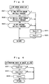
- Fig. 5 is a flowchart showing the action of accident judgment which is mainly the action of the accident judgment unit 340.
- Fig. 6 schematically illustrates the judgement process.
- This embodiment employs the acceleration calculated from the vehicle speed V as a parameter for the accident judgment. More specifically, when the acceleration reaches an excessive rate and the fall down is detected, it is then judged that the traffic accident occurs.
- the vehicle may be fallen down (at t1), slid over the road surface, and then crushed (at t2).
- the acceleration is not largely changed at the timing of detection of the fall down.
- the accident judgment is modified to give a correct judgment when the change in the acceleration and the fall down are detected at an interval of time.
- Step S60 shown in Fig. 5 the accident break flag Fcv (Fig. 4) is examined.
- the flag Fcv is set up, it is then judged that the accident occurs and the procedure jumps to Step S75.
- the flag Fcv is in its reset state, the procedure goes to Step s61.
- Step S61 It is compared at Step S61 between the absolute of the acceleration dV at the current and an accident judgment reference acceleration dVref1 which is set to a larger rate (about 1.0 G) than the maximum (about 0.8 G) deceleration generated during the braking action. Accordingly, when the current acceleration dV exceeds the reference acceleration dVref1, it is judged that the accident occurs regardless of the fall down and the procedure jumps to Step S75. When the acceleration dV is not higher than the reference acceleration dVref1, the procedure moves to Step S62.
- the not-informing reference speed Vref is an upper limit of a range of the speed where the driver is assumed not to suffer from serious injury when the vehicle crashes or falls down. In this embodiment, the not-informing reference speed Vref is set to 10 km/h. As the range of the speeds where the driver rarely suffers from serious injury when the vehicle crashes or falls down is varied depending on the size, the weight, and the shape of the vehicle, the not-informing reference speed Vref may be a rate dedicated to one particular type of the vehicle.
- a fall-down flag Fdown is examined.
- the fall-down flag Fdown is turned on when the fall down continues throughout a specific length of time as will be described later in more detail.
- the fall-down flag Fdown is normally turned off.
- the procedure goes to S64. It is then compared at Step S64 between the current inclination angle ⁇ measured by the inclination sensor 2 and a fall-down judgment reference angle ⁇ roll. When the current inclination angle ⁇ is not higher than the fall-down judgment reference angle ⁇ roll, the procedure goes to Step S64. On the contrary, if the current inclination angle ⁇ exceed the fall-down judgment reference angle ⁇ roll, it is judged that the vehicle is fell down and the procedure goes to Step S65.
- Step S65 when the fall-down timer Tdown is not started, it is started. It is then examined at Step S66 whether or not the fall-down timer Tdown is timed out. When the current inclination angle ⁇ returns back to below the fall-down judgment reference angle ⁇ roll before the fall-down timer Tdown is timed out, it is judged that the fall-down is caused by any other event than the traffic accident and the procedure jumps to Step S69.
- Step S67 When the fall-down timer Tdown is timed out before the current inclination angle ⁇ returns back to below the fall-down judgment reference angle ⁇ roll, the procedure goes to Step S67 for setting the fall-down flag Fdown on.
- a flag holding timer Th1 is started for maintaining the fall-down flag Fdown in its set-up state throughout a specific length of time.
- the specific length of time ⁇ t1 is calculated from a series of experiments as being equal to a difference (t2-t1) shown in Fig. 6.
- an acceleration excess flag Fd is examined which is set up when the negative acceleration becomes excessively large as will be described later.
- the acceleration excess flag Fd is normally in its reset state and the procedure goes to Step S70. It is compared at Step S70 between the absolute of the current acceleration dV and an accident judgment reference acceleration dVref2.
- the accident judgment reference acceleration dVref2 is set to a lower limit (0.3 to 0.4 G) of a range of the acceleration which may be encountered when the vehicle crashes or falls down. As a result, when the current acceleration dV is not higher than the accident judgment reference acceleration dvref2, the procedure is terminated.
- Step S71 When it is judged that the current acceleration dV is higher than the accident judgment reference acceleration dVref2, the acceleration excess flag Fd is set up at Step S71. This is followed by Step S72 where a flag holding timer Th2 is started for maintaining the acceleration excess flag Fd in its set-up state throughout a predetermined length of time ⁇ t2.
- the length of time ⁇ t2 is calculated from a series of experiments as is equal to a difference (t4-t3) shown in Fig. 6.
- Step s73 It is then examined at Step s73 whether or not the fall-down timer Tdown and the acceleration excess flag Fd are in their set-up state. When so, the procedure goes to Step S75 for setting an accident flag Fac on.
- Step S74 the two flag holding timers Th1 and Th2 are examined.
- the timer is timed out, its corresponding fall-down flag Fdown or acceleration excess flag Fd is reset to zero.
- the embodiment permits the vehicle to be judged that it met with an accident when the inclination angle remains higher than the reference level throughout a period of time longer than a predetermined length. Accordingly, if the vehicle in its not-running mode falls down, it can be stood back by its driver and judged that it met with no traffic accident, thus eliminating an unnecessary action of informing.
- Step S7 follows where the accident flag Fac is examined.
- the procedure goes back to Step S2.
- the accident flag Fac is set up, the procedure moves to Step S8 for carrying out a reset stand-by process.
- Fig. 7 is a flowchart showing the reset stand-by process.
- Step S81 a data collection timer Tinfo (set to two seconds in this embodiment) is started.
- Step 582 a reset stand-by timer Twait (set to ten seconds in this embodiment) is started. It is then examined at Step S83 whether the data collection timer Tinfo is timed out or not. When the timer Tinfo is timed out, the procedure goes to Step S84 where the position data collecting action of the accident data memory 71 in the accident informing module 7 is stopped.
- Step S85 It is then examined at Step S85 whether the reset switch 5 is closed or not.
- the procedure moves to Step S86 for displaying a message "System OFF" on the screen of the display 6.
- Step S87 the action of the automatic accident informing system is terminated.
- Step S88 When the reset switch 5 is not closed, it is examined at Step S88 whether the reset stand-by timer Twait is timed out or not. The steps from S83 to S88 are repeated until the timer Twait is timed out. When it is judged that the timer Twait is timed out, this subroutine is terminated and the procedure returns back to Step S9 shown in Fig. 2.
- Step S9 the parties to be informed and the position data saved in the accident data memory 71 are transferred to the transmitter 72 in the accident informing module 7.
- Step S10 a group of the information is transmitted in a radio communications protocol such as PHS to the parties to be informed.
- the present invention is not limited to the embodiment where the position data of the vehicle to be informed when the accident occurs is generated and supplied by the GPS unit 32.
- the communications unit 72 may produce and supply a position data based on the positioning operation of the PHS function.
- the accident judgment is made when the negative acceleration is detected and the vehicle is inclined excessively. If the vehicle is hit at its back by any other vehicle, the positive acceleration is created. Accordingly, the accident judgment may be made when the positive acceleration is detected and the inclination of the vehicle is large.
- the present invention provides the following advantages.
Landscapes
- Engineering & Computer Science (AREA)
- Mechanical Engineering (AREA)
- Computer Security & Cryptography (AREA)
- Business, Economics & Management (AREA)
- Emergency Management (AREA)
- Physics & Mathematics (AREA)
- General Physics & Mathematics (AREA)
- Emergency Alarm Devices (AREA)
- Time Recorders, Dirve Recorders, Access Control (AREA)
- Traffic Control Systems (AREA)
Abstract
Description
Claims (4)
- An automatic accident informing apparatus for a two-wheel vehicle having an accident detecting means for detecting an accident of the vehicle and an accident informing means for informing an external party(s) of the accident, wherein the accident detecting means comprises:an inclination sensor for measuring the inclination angle of the vehicle; andan accident judging means for judging that the vehicle met with the accident when the inclination angle of the vehicle measured by the inclination sensor remains higher than a predetermine degree throughout a specific length of time.
- An automatic accident informing apparatus for a two-wheel vehicle according to claim 1, further comprising:whereina vehicle speed history saving means for saving the history of speeds of the vehicle; andan acceleration calculating means for calculating the acceleration of the vehicle from a change in the vehicle speed saved in the vehicle speed history saving means,
the accident judging means judges that the vehicle met with the accident when the inclination angle of the vehicle remains higher than the predetermine degree throughout the specific length of time about a time while the acceleration of the vehicle is greater than a predetermined level. - An automatic accident informing apparatus for a two-wheel vehicle having an accident detecting means for detecting an accident of the vehicle and an accident informing means for informing an external party(s) of the accident, comprising:a vehicle speed history saving means for saving the history of speeds of the vehicle;an acceleration calculating means for calculating the acceleration of the vehicle from a change in the vehicle speed saved in the vehicle speed history saving means; anda line break detecting means for detecting the break in particular circuitry lines, whereinthe accident detecting means judges that the vehicle met with the accident when the line break detecting means detects break in the circuitry lines about a time while the acceleration of the vehicle is greater than a predetermined level.
- An automatic accident informing apparatus for a two-wheel vehicle according to any of claims 1 to 3, further comprising:a cancel switch for canceling at least either the action of detecting the accident of the accident detecting means or the action of informing of the accident of the accident informing means, whereinthe action of the accident detecting means or the accident informing means can be canceled only within a particular period of time after the occurrence of the accident but not when the particular period of time has passed.
Applications Claiming Priority (3)
| Application Number | Priority Date | Filing Date | Title |
|---|---|---|---|
| JP2000148857A JP4345948B2 (en) | 2000-05-19 | 2000-05-19 | Motorcycle accident notification system |
| JP2000148857 | 2000-05-19 | ||
| PCT/JP2001/003885 WO2001087695A1 (en) | 2000-05-19 | 2001-05-10 | Automatic accident reporting apparatus for two-wheeled vehicles |
Publications (3)
| Publication Number | Publication Date |
|---|---|
| EP1197426A1 true EP1197426A1 (en) | 2002-04-17 |
| EP1197426A4 EP1197426A4 (en) | 2006-02-08 |
| EP1197426B1 EP1197426B1 (en) | 2009-04-29 |
Family
ID=18654814
Family Applications (1)
| Application Number | Title | Priority Date | Filing Date |
|---|---|---|---|
| EP01930016A Expired - Lifetime EP1197426B1 (en) | 2000-05-19 | 2001-05-10 | Automatic accident reporting apparatus for two-wheeled vehicles |
Country Status (9)
| Country | Link |
|---|---|
| US (1) | US6587042B2 (en) |
| EP (1) | EP1197426B1 (en) |
| JP (1) | JP4345948B2 (en) |
| KR (1) | KR100468405B1 (en) |
| CN (1) | CN1140434C (en) |
| DE (1) | DE60138517D1 (en) |
| NO (2) | NO329860B1 (en) |
| TW (1) | TW587561U (en) |
| WO (1) | WO2001087695A1 (en) |
Cited By (12)
| Publication number | Priority date | Publication date | Assignee | Title |
|---|---|---|---|---|
| WO2004067365A1 (en) * | 2003-01-30 | 2004-08-12 | Sauro Bianchelli | Integrated method and system for the safety control of scooters and motorbikes |
| EP1463013A3 (en) * | 2003-03-27 | 2007-12-05 | Shimano Inc. | Bicycle information processing apparatus with memory protection |
| WO2008145510A1 (en) * | 2007-05-30 | 2008-12-04 | Continental Teves Ag & Co. Ohg | Transmission of an emergency call from a motor cycle |
| WO2011076956A1 (en) | 2009-12-21 | 2011-06-30 | Telefónica, S.A. | Portable apparatus and method for detecting and notifying of vehicle accidents |
| EP2026287A3 (en) * | 2007-06-18 | 2011-08-24 | Kawasaki Jukogyo Kabushiki Kaisha | Event data recorder, motorcycle, and information recording method |
| WO2013131670A1 (en) * | 2012-03-08 | 2013-09-12 | Robert Bosch Gmbh | Method for preventing an accident or for reducing the effects of the accident for a rider |
| US8725312B2 (en) | 2011-08-12 | 2014-05-13 | Kawasaki Jukogyo Kabushiki Kaisha | System for obtaining information in vehicle |
| EP2881921A1 (en) * | 2013-12-06 | 2015-06-10 | Alps Electric Co., Ltd. | Vehicle accident notification apparatus |
| TWI657945B (en) * | 2018-01-26 | 2019-05-01 | 宏佳騰動力科技股份有限公司 | Locomotive accident detection and notification method |
| US10773672B2 (en) | 2017-06-08 | 2020-09-15 | Yamaha Hatsudoki Kabushiki Kaisha | Leaning vehicle |
| WO2022194430A1 (en) * | 2021-03-16 | 2022-09-22 | Robert Bosch Gmbh | Method for determining the speed of a vehicle in the event of an accident |
| WO2023198408A1 (en) * | 2022-04-14 | 2023-10-19 | Volkswagen Aktiengesellschaft | Emergency call system, vehicle and method for transmitting an emergency call |
Families Citing this family (56)
| Publication number | Priority date | Publication date | Assignee | Title |
|---|---|---|---|---|
| FR2842493B1 (en) * | 2002-07-18 | 2005-09-09 | De Meder Laurent Bourgine | METHOD AND DEVICE FOR SECURITY FOR VEHICLE TWO WHEELS AND THE LIKE |
| JP2004280345A (en) * | 2003-03-14 | 2004-10-07 | Omron Corp | Terminal block device |
| FR2865994B1 (en) * | 2004-02-10 | 2007-04-27 | J C Decaux | BICYCLE EQUIPPED WITH AN INBOARD CONTROL SYSTEM |
| US7129826B2 (en) * | 2004-05-28 | 2006-10-31 | Motorola, Inc. | Localized accident notification |
| JP5259917B2 (en) * | 2005-01-11 | 2013-08-07 | 三菱エンジニアリングプラスチックス株式会社 | Blend of polyamide resin composition, method for producing the same, and molded article |
| JP2006307782A (en) * | 2005-04-28 | 2006-11-09 | Yamaha Motor Co Ltd | VEHICLE ENGINE CONTROL DEVICE, CONTROL METHOD AND ITS PROGRAM |
| US7344153B1 (en) * | 2005-07-18 | 2008-03-18 | Manneh Dimitri J | Multiple sensor controlled vehicle airbag deployment system |
| JP4512112B2 (en) * | 2005-11-14 | 2010-07-28 | 富士通テン株式会社 | Driving information recording device |
| JP4025347B2 (en) * | 2005-11-14 | 2007-12-19 | 富士通テン株式会社 | Driving information recording device |
| JP2007287035A (en) * | 2006-04-19 | 2007-11-01 | Fujifilm Corp | Video recording system and video recording apparatus |
| JP5111843B2 (en) * | 2006-12-26 | 2013-01-09 | 本田技研工業株式会社 | Motorcycle riding recorder |
| JP5204427B2 (en) * | 2007-06-18 | 2013-06-05 | 川崎重工業株式会社 | Event data recorder |
| JP5039444B2 (en) * | 2007-06-18 | 2012-10-03 | 川崎重工業株式会社 | Vehicle and information recording method |
| JP4780155B2 (en) * | 2008-08-01 | 2011-09-28 | 株式会社デンソー | In-vehicle device |
| JP4828588B2 (en) * | 2008-09-26 | 2011-11-30 | 株式会社平和 | Game machine |
| JP4828589B2 (en) * | 2008-09-26 | 2011-11-30 | 株式会社平和 | Game machine |
| US20100079266A1 (en) * | 2008-09-30 | 2010-04-01 | Holt Richard K | Motorcycle accident warning alarm |
| JP5279678B2 (en) * | 2009-10-19 | 2013-09-04 | 本田技研工業株式会社 | Portable work machine |
| ES2384248B1 (en) * | 2009-12-28 | 2013-04-22 | Luis Antonio García Sánchez | EMERGENCY DEVICE FOR LOCATION OF ACCIDENTED MOTORCYCLES. |
| US8907772B1 (en) * | 2010-09-29 | 2014-12-09 | Cyber Physical Systems, Inc. | System and method for automatic unsafe driving determination and notification |
| ES2385154B1 (en) * | 2010-12-23 | 2013-05-23 | Francisco Javier LOBATO RAPOSO | DEVICE AND PROCEDURE OF LOCATION AND ORIENTATION FOR VEHICLES IN CASES OF EMERGENCY, ESPECIALLY INTENDED IN ITS APPLICATION TO MOTORCYCLES. |
| US20130079973A1 (en) * | 2011-09-24 | 2013-03-28 | Taif University | System for Communicating A Vehicle Position and Speed During Accident |
| CN103085749B (en) * | 2011-10-31 | 2016-03-30 | 上海博泰悦臻网络技术服务有限公司 | The processing method of vehicle emergency and device, onboard system |
| JP5861236B2 (en) * | 2012-01-16 | 2016-02-16 | 小林鋲螺株式会社 | Vehicle lamp, its storage holder, vehicle |
| FR2996340B1 (en) * | 2012-10-03 | 2014-10-31 | Commissariat Energie Atomique | ALARM TRANSMISSION SYSTEM |
| AU2014223307B2 (en) * | 2013-03-01 | 2016-12-15 | Federation Enterprises (Wa) Pty Ltd | Bicycle camera |
| US9247040B1 (en) * | 2013-09-24 | 2016-01-26 | Lytx, Inc. | Vehicle event recorder mobile phone mount |
| JP5730975B2 (en) * | 2013-10-11 | 2015-06-10 | 富士重工業株式会社 | Electric vehicle |
| JP6131871B2 (en) * | 2014-01-31 | 2017-05-24 | 株式会社デンソー | Vehicle occupant protection device |
| JP6024696B2 (en) | 2014-03-27 | 2016-11-16 | 株式会社デンソー | Communication device |
| EP3345792B1 (en) * | 2014-06-24 | 2019-09-11 | Robert Bosch Gmbh | Automatic alerting device and automatic alerting method |
| DE102014216966A1 (en) * | 2014-08-26 | 2016-03-03 | Canyon Bicycles Gmbh | Bicycle service system as well as bicycle service procedures |
| US10144527B2 (en) * | 2015-03-25 | 2018-12-04 | Skyfront Corp. | Flight controller with generator control |
| JP6572114B2 (en) * | 2015-12-01 | 2019-09-04 | 株式会社小糸製作所 | Vehicle lamp control device and vehicle lamp system |
| KR101882478B1 (en) * | 2017-03-06 | 2018-07-30 | 주식회사 아이오티스퀘어 | System for detecting dangerous situation of two-wheeled vehicle using sensor and transfer emergency rescue signal method using the same |
| JP6938975B2 (en) * | 2017-03-10 | 2021-09-22 | 日本電気株式会社 | Hazardous area notification device, dangerous area information providing device, dangerous area notification method, program |
| WO2018216668A1 (en) * | 2017-05-22 | 2018-11-29 | Cach株式会社 | Monitoring system and monitoring method |
| CN107085229B (en) * | 2017-05-22 | 2018-03-23 | 傅皓衍 | Collecting method |
| CN107571944A (en) * | 2017-08-30 | 2018-01-12 | 北京骑骑智享科技发展有限公司 | Alarm method and device |
| KR101965244B1 (en) * | 2017-11-14 | 2019-04-03 | 이화여자대학교 산학협력단 | Safety apparatus and safety drive education system including the apparatus for bicycles |
| CN108173908A (en) * | 2017-12-13 | 2018-06-15 | 东莞市千林电子科技有限公司 | VCM Vehicle Condition Monitoring chip, smart lock, bicycle, monitoring method and Cloud Server |
| JP7094728B2 (en) * | 2018-03-07 | 2022-07-04 | Dynabook株式会社 | Electronic devices, event detection methods and programs |
| CN108663045B (en) * | 2018-04-28 | 2024-05-07 | 山东交通学院 | Riding carrier gesture recognition alarm method and gesture monitoring alarm device |
| CN110683165A (en) * | 2018-06-20 | 2020-01-14 | 北京三快在线科技有限公司 | Distribution box and information prompt method applied to distribution box |
| JP7226052B2 (en) | 2019-04-16 | 2023-02-21 | スズキ株式会社 | Accident Judgment System, Accident Judgment Method, Program |
| US11878761B2 (en) | 2019-12-06 | 2024-01-23 | Gekot, Inc. | Collision alert systems and methods for micromobility vehicles |
| DE102020201224A1 (en) * | 2020-01-31 | 2021-08-05 | Robert Bosch Gesellschaft mit beschränkter Haftung | Method and device for classifying an accident involving a two-wheeled vehicle |
| US12227103B1 (en) * | 2020-05-13 | 2025-02-18 | William S. Lerner | Energy supply status indication for a vehicle |
| US11760258B1 (en) * | 2020-05-13 | 2023-09-19 | William S. Lerner | Indicators to identify status and safety of vehicles |
| JP7290614B2 (en) * | 2020-08-28 | 2023-06-13 | Necプラットフォームズ株式会社 | Reporting system, communication device, reporting method, and program |
| EP4418228A1 (en) * | 2021-10-14 | 2024-08-21 | Atressa Global Corporation, S.L. | Method and system for providing assistance in vehicle accidents |
| TWI789952B (en) * | 2021-10-18 | 2023-01-11 | 中華電信股份有限公司 | Detection system and detection method for driving behavior |
| CN115249402A (en) * | 2021-11-23 | 2022-10-28 | 深圳市发掘科技有限公司 | Method and device for rapidly judging accident of two-wheeled vehicle, computer equipment and storage medium |
| EP4498095A1 (en) * | 2023-07-28 | 2025-01-29 | Toyota Jidosha Kabushiki Kaisha | Method and apparatus for detecting a collision between an obstacle and a moving vehicle |
| CN118046984A (en) * | 2024-02-21 | 2024-05-17 | 湖南喜宝达信息科技有限公司 | Motorcycle accident detection notification method, motorcycle and storage medium |
| CN118470897B (en) * | 2024-05-24 | 2025-01-10 | 深圳市子午创新技术有限公司 | Riding falling early warning method, riding falling early warning device, riding falling early warning equipment and storage medium |
Family Cites Families (14)
| Publication number | Priority date | Publication date | Assignee | Title |
|---|---|---|---|---|
| US3772643A (en) | 1972-03-06 | 1973-11-13 | E Dodd | Tilt-actuated safety device |
| JPS5816399A (en) | 1981-07-20 | 1983-01-31 | オムロン株式会社 | Automatic communicator for car accidents |
| JPS6428086A (en) | 1987-07-21 | 1989-01-30 | Aisin Seiki | Safety device for motorcycle |
| JPS6431294A (en) | 1987-07-27 | 1989-02-01 | Hino Motors Ltd | Vehicle abnormality sensing informing device |
| JP3058942B2 (en) | 1991-06-27 | 2000-07-04 | 三菱電機株式会社 | Navigation device |
| JP3172266B2 (en) | 1992-07-02 | 2001-06-04 | マツダ株式会社 | Automatic notification device |
| JP3308018B2 (en) | 1993-02-25 | 2002-07-29 | マツダ株式会社 | Emergency call device for vehicles |
| US5777290A (en) * | 1996-07-08 | 1998-07-07 | Harley-Davidson Motor Company | Bank angle sensor |
| JPH10104258A (en) | 1996-09-27 | 1998-04-24 | Fujitsu Ten Ltd | Accident notifying system |
| JPH11350983A (en) * | 1998-06-05 | 1999-12-21 | Honda Motor Co Ltd | Notification device |
| JP2000118336A (en) | 1998-10-12 | 2000-04-25 | Toyota Motor Corp | Vehicle fall detection device and emergency call system |
| US6034594A (en) * | 1998-10-20 | 2000-03-07 | Gray; William R. | Motorcycle warning device |
| US6360838B1 (en) * | 2000-01-11 | 2002-03-26 | Skye Associates, Llc | System for balancing a two-wheeled vehicle at rest |
| US6268794B1 (en) * | 2000-01-21 | 2001-07-31 | Harley-Davidson Motor Company Group, Inc. | Integrated security, tip-over, and turn signal system |
-
2000
- 2000-05-19 JP JP2000148857A patent/JP4345948B2/en not_active Expired - Fee Related
-
2001
- 2001-05-03 TW TW092216425U patent/TW587561U/en unknown
- 2001-05-10 US US09/926,227 patent/US6587042B2/en not_active Expired - Lifetime
- 2001-05-10 EP EP01930016A patent/EP1197426B1/en not_active Expired - Lifetime
- 2001-05-10 CN CNB018003141A patent/CN1140434C/en not_active Expired - Fee Related
- 2001-05-10 DE DE60138517T patent/DE60138517D1/en not_active Expired - Lifetime
- 2001-05-10 WO PCT/JP2001/003885 patent/WO2001087695A1/en not_active Ceased
- 2001-05-10 KR KR10-2001-7011891A patent/KR100468405B1/en not_active Expired - Fee Related
-
2002
- 2002-01-21 NO NO20020322A patent/NO329860B1/en not_active IP Right Cessation
-
2010
- 2010-08-04 NO NO20101101A patent/NO331738B1/en not_active IP Right Cessation
Cited By (14)
| Publication number | Priority date | Publication date | Assignee | Title |
|---|---|---|---|---|
| WO2004067365A1 (en) * | 2003-01-30 | 2004-08-12 | Sauro Bianchelli | Integrated method and system for the safety control of scooters and motorbikes |
| EP1463013A3 (en) * | 2003-03-27 | 2007-12-05 | Shimano Inc. | Bicycle information processing apparatus with memory protection |
| WO2008145510A1 (en) * | 2007-05-30 | 2008-12-04 | Continental Teves Ag & Co. Ohg | Transmission of an emergency call from a motor cycle |
| EP2026287A3 (en) * | 2007-06-18 | 2011-08-24 | Kawasaki Jukogyo Kabushiki Kaisha | Event data recorder, motorcycle, and information recording method |
| WO2011076956A1 (en) | 2009-12-21 | 2011-06-30 | Telefónica, S.A. | Portable apparatus and method for detecting and notifying of vehicle accidents |
| US8725312B2 (en) | 2011-08-12 | 2014-05-13 | Kawasaki Jukogyo Kabushiki Kaisha | System for obtaining information in vehicle |
| WO2013131670A1 (en) * | 2012-03-08 | 2013-09-12 | Robert Bosch Gmbh | Method for preventing an accident or for reducing the effects of the accident for a rider |
| EP2881921A1 (en) * | 2013-12-06 | 2015-06-10 | Alps Electric Co., Ltd. | Vehicle accident notification apparatus |
| US10773672B2 (en) | 2017-06-08 | 2020-09-15 | Yamaha Hatsudoki Kabushiki Kaisha | Leaning vehicle |
| TWI657945B (en) * | 2018-01-26 | 2019-05-01 | 宏佳騰動力科技股份有限公司 | Locomotive accident detection and notification method |
| WO2022194430A1 (en) * | 2021-03-16 | 2022-09-22 | Robert Bosch Gmbh | Method for determining the speed of a vehicle in the event of an accident |
| WO2023198408A1 (en) * | 2022-04-14 | 2023-10-19 | Volkswagen Aktiengesellschaft | Emergency call system, vehicle and method for transmitting an emergency call |
| DE102022203781A1 (en) | 2022-04-14 | 2023-10-19 | Volkswagen Aktiengesellschaft | Emergency call system, vehicle and method for sending an emergency call |
| DE102022203781B4 (en) | 2022-04-14 | 2024-02-01 | Volkswagen Aktiengesellschaft | Emergency call system, vehicle and method for sending an emergency call |
Also Published As
| Publication number | Publication date |
|---|---|
| NO20020322D0 (en) | 2002-01-21 |
| WO2001087695A1 (en) | 2001-11-22 |
| NO20020322L (en) | 2002-01-21 |
| US6587042B2 (en) | 2003-07-01 |
| TW587561U (en) | 2004-05-11 |
| DE60138517D1 (en) | 2009-06-10 |
| KR100468405B1 (en) | 2005-01-27 |
| CN1362923A (en) | 2002-08-07 |
| EP1197426B1 (en) | 2009-04-29 |
| JP4345948B2 (en) | 2009-10-14 |
| NO329860B1 (en) | 2011-01-17 |
| KR20020022642A (en) | 2002-03-27 |
| EP1197426A4 (en) | 2006-02-08 |
| JP2001328580A (en) | 2001-11-27 |
| NO20101101L (en) | 2002-01-21 |
| CN1140434C (en) | 2004-03-03 |
| US20020158754A1 (en) | 2002-10-31 |
| NO331738B1 (en) | 2012-03-12 |
Similar Documents
| Publication | Publication Date | Title |
|---|---|---|
| EP1197426B1 (en) | Automatic accident reporting apparatus for two-wheeled vehicles | |
| US7138922B2 (en) | Drowsy driver monitoring and prevention system | |
| US7557693B2 (en) | Multi-function warning system for vehicle and related control method | |
| WO1998030987A3 (en) | Remote detecting system and method | |
| US20190147746A1 (en) | Device for identifying an accident situation of an open road vehicle | |
| US20040075553A1 (en) | Antitheft apparatus and antitheft auxiliary device | |
| CN106412051A (en) | Urban vehicle tracking anti-theft system | |
| CN113223281A (en) | Vehicle tumble detection method and system and vehicle | |
| CN110166946B (en) | A method and system for monitoring highway vehicle information based on wireless communication | |
| WO2016182114A1 (en) | Vehicle accident notification system, and method for controlling same | |
| US6259376B1 (en) | Tolling apparatus | |
| CN116572884B (en) | Intelligent vehicle-mounted security system for buses | |
| JP3073960B2 (en) | Vehicle emergency call system and vehicle emergency call device | |
| KR100261436B1 (en) | Apparatus and method for notification of automobile accident | |
| CN112315107A (en) | Intelligent driving shoe based on automobile safety device and warning method thereof | |
| CN223817034U (en) | A cycling safety control device that detects whether a user is wearing a helmet. | |
| JP2001351192A (en) | Method for collecting traffic information by axle load sensor and device for the same | |
| CN115862186B (en) | Motorcycle safety monitoring system | |
| CN208774745U (en) | A vehicle safety braking device with a driver's bayonet payment | |
| CN110262084A (en) | Whether a kind of driver for identification diverts one's attention the sunglasses driven and method | |
| JPH04366714A (en) | In-vehicle position calculation device | |
| CN210777187U (en) | Early warning device for dangerous driving state of vehicle | |
| CN107021011A (en) | A kind of Lane Departure Warning System monitored in real time | |
| CN118003974A (en) | New energy automobile battery pack collision detection method and device and new energy automobile | |
| KR100202111B1 (en) | Driver drowsiness detector |
Legal Events
| Date | Code | Title | Description |
|---|---|---|---|
| PUAI | Public reference made under article 153(3) epc to a published international application that has entered the european phase |
Free format text: ORIGINAL CODE: 0009012 |
|
| 17P | Request for examination filed |
Effective date: 20011022 |
|
| AK | Designated contracting states |
Kind code of ref document: A1 Designated state(s): AT BE CH CY DE DK ES FI FR GB GR IE IT LI LU MC NL PT SE TR |
|
| RBV | Designated contracting states (corrected) |
Designated state(s): DE FI FR GB IT SE |
|
| A4 | Supplementary search report drawn up and despatched |
Effective date: 20051229 |
|
| GRAP | Despatch of communication of intention to grant a patent |
Free format text: ORIGINAL CODE: EPIDOSNIGR1 |
|
| GRAS | Grant fee paid |
Free format text: ORIGINAL CODE: EPIDOSNIGR3 |
|
| GRAA | (expected) grant |
Free format text: ORIGINAL CODE: 0009210 |
|
| AK | Designated contracting states |
Kind code of ref document: B1 Designated state(s): DE FI FR GB IT SE |
|
| REG | Reference to a national code |
Ref country code: GB Ref legal event code: FG4D |
|
| REF | Corresponds to: |
Ref document number: 60138517 Country of ref document: DE Date of ref document: 20090610 Kind code of ref document: P |
|
| REG | Reference to a national code |
Ref country code: SE Ref legal event code: TRGR |
|
| PLBE | No opposition filed within time limit |
Free format text: ORIGINAL CODE: 0009261 |
|
| STAA | Information on the status of an ep patent application or granted ep patent |
Free format text: STATUS: NO OPPOSITION FILED WITHIN TIME LIMIT |
|
| 26N | No opposition filed |
Effective date: 20100201 |
|
| PG25 | Lapsed in a contracting state [announced via postgrant information from national office to epo] |
Ref country code: IT Free format text: LAPSE BECAUSE OF NON-PAYMENT OF DUE FEES Effective date: 20090510 |
|
| PGFP | Annual fee paid to national office [announced via postgrant information from national office to epo] |
Ref country code: SE Payment date: 20110512 Year of fee payment: 11 Ref country code: FR Payment date: 20110523 Year of fee payment: 11 |
|
| PGRI | Patent reinstated in contracting state [announced from national office to epo] |
Ref country code: IT Effective date: 20110616 |
|
| PGFP | Annual fee paid to national office [announced via postgrant information from national office to epo] |
Ref country code: FI Payment date: 20110511 Year of fee payment: 11 |
|
| REG | Reference to a national code |
Ref country code: GB Ref legal event code: 746 Effective date: 20120207 |
|
| REG | Reference to a national code |
Ref country code: DE Ref legal event code: R084 Ref document number: 60138517 Country of ref document: DE Effective date: 20120209 |
|
| REG | Reference to a national code |
Ref country code: SE Ref legal event code: EUG |
|
| PG25 | Lapsed in a contracting state [announced via postgrant information from national office to epo] |
Ref country code: FI Free format text: LAPSE BECAUSE OF NON-PAYMENT OF DUE FEES Effective date: 20120510 |
|
| PG25 | Lapsed in a contracting state [announced via postgrant information from national office to epo] |
Ref country code: SE Free format text: LAPSE BECAUSE OF NON-PAYMENT OF DUE FEES Effective date: 20120511 |
|
| REG | Reference to a national code |
Ref country code: FR Ref legal event code: ST Effective date: 20130131 |
|
| PG25 | Lapsed in a contracting state [announced via postgrant information from national office to epo] |
Ref country code: FR Free format text: LAPSE BECAUSE OF NON-PAYMENT OF DUE FEES Effective date: 20120531 |
|
| PGFP | Annual fee paid to national office [announced via postgrant information from national office to epo] |
Ref country code: GB Payment date: 20150506 Year of fee payment: 15 |
|
| PGFP | Annual fee paid to national office [announced via postgrant information from national office to epo] |
Ref country code: IT Payment date: 20150515 Year of fee payment: 15 |
|
| PGFP | Annual fee paid to national office [announced via postgrant information from national office to epo] |
Ref country code: DE Payment date: 20160504 Year of fee payment: 16 |
|
| GBPC | Gb: european patent ceased through non-payment of renewal fee |
Effective date: 20160510 |
|
| PG25 | Lapsed in a contracting state [announced via postgrant information from national office to epo] |
Ref country code: IT Free format text: LAPSE BECAUSE OF NON-PAYMENT OF DUE FEES Effective date: 20160510 |
|
| PG25 | Lapsed in a contracting state [announced via postgrant information from national office to epo] |
Ref country code: GB Free format text: LAPSE BECAUSE OF NON-PAYMENT OF DUE FEES Effective date: 20160510 |
|
| REG | Reference to a national code |
Ref country code: DE Ref legal event code: R119 Ref document number: 60138517 Country of ref document: DE |
|
| PG25 | Lapsed in a contracting state [announced via postgrant information from national office to epo] |
Ref country code: DE Free format text: LAPSE BECAUSE OF NON-PAYMENT OF DUE FEES Effective date: 20171201 |