EP1197403A2 - Gurtstraffer und Kraftbegrenzer - Google Patents
Gurtstraffer und Kraftbegrenzer Download PDFInfo
- Publication number
- EP1197403A2 EP1197403A2 EP01850167A EP01850167A EP1197403A2 EP 1197403 A2 EP1197403 A2 EP 1197403A2 EP 01850167 A EP01850167 A EP 01850167A EP 01850167 A EP01850167 A EP 01850167A EP 1197403 A2 EP1197403 A2 EP 1197403A2
- Authority
- EP
- European Patent Office
- Prior art keywords
- piston
- drum
- cylinder
- reel mechanism
- gear
- Prior art date
- Legal status (The legal status is an assumption and is not a legal conclusion. Google has not performed a legal analysis and makes no representation as to the accuracy of the status listed.)
- Granted
Links
Images


Classifications
-
- B—PERFORMING OPERATIONS; TRANSPORTING
- B60—VEHICLES IN GENERAL
- B60R—VEHICLES, VEHICLE FITTINGS, OR VEHICLE PARTS, NOT OTHERWISE PROVIDED FOR
- B60R22/00—Safety belts or body harnesses in vehicles
- B60R22/34—Belt retractors, e.g. reels
- B60R22/46—Reels with means to tension the belt in an emergency by forced winding up
- B60R22/4619—Transmission of tensioning power by cable, e.g. using a clutch on reel side
-
- B—PERFORMING OPERATIONS; TRANSPORTING
- B60—VEHICLES IN GENERAL
- B60R—VEHICLES, VEHICLE FITTINGS, OR VEHICLE PARTS, NOT OTHERWISE PROVIDED FOR
- B60R22/00—Safety belts or body harnesses in vehicles
- B60R22/34—Belt retractors, e.g. reels
- B60R22/46—Reels with means to tension the belt in an emergency by forced winding up
- B60R22/4676—Reels with means to tension the belt in an emergency by forced winding up comprising energy-absorbing means operating between belt reel and retractor frame
-
- B—PERFORMING OPERATIONS; TRANSPORTING
- B60—VEHICLES IN GENERAL
- B60R—VEHICLES, VEHICLE FITTINGS, OR VEHICLE PARTS, NOT OTHERWISE PROVIDED FOR
- B60R21/00—Arrangements or fittings on vehicles for protecting or preventing injuries to occupants or pedestrians in case of accidents or other traffic risks
- B60R2021/0002—Type of accident
- B60R2021/0018—Roll-over
-
- B—PERFORMING OPERATIONS; TRANSPORTING
- B60—VEHICLES IN GENERAL
- B60R—VEHICLES, VEHICLE FITTINGS, OR VEHICLE PARTS, NOT OTHERWISE PROVIDED FOR
- B60R22/00—Safety belts or body harnesses in vehicles
- B60R22/28—Safety belts or body harnesses in vehicles incorporating energy-absorbing devices
- B60R2022/288—Safety belts or body harnesses in vehicles incorporating energy-absorbing devices with means to adjust or regulate the amount of energy to be absorbed
-
- B—PERFORMING OPERATIONS; TRANSPORTING
- B60—VEHICLES IN GENERAL
- B60R—VEHICLES, VEHICLE FITTINGS, OR VEHICLE PARTS, NOT OTHERWISE PROVIDED FOR
- B60R22/00—Safety belts or body harnesses in vehicles
- B60R22/34—Belt retractors, e.g. reels
- B60R22/46—Reels with means to tension the belt in an emergency by forced winding up
- B60R22/4628—Reels with means to tension the belt in an emergency by forced winding up characterised by fluid actuators, e.g. pyrotechnic gas generators
- B60R2022/4661—Reels with means to tension the belt in an emergency by forced winding up characterised by fluid actuators, e.g. pyrotechnic gas generators comprising venting means, e.g. for avoiding overpressure in case of fire or for allowing return motion with energy absorption
-
- B—PERFORMING OPERATIONS; TRANSPORTING
- B60—VEHICLES IN GENERAL
- B60R—VEHICLES, VEHICLE FITTINGS, OR VEHICLE PARTS, NOT OTHERWISE PROVIDED FOR
- B60R22/00—Safety belts or body harnesses in vehicles
- B60R22/34—Belt retractors, e.g. reels
- B60R22/46—Reels with means to tension the belt in an emergency by forced winding up
- B60R2022/4685—Reels with means to tension the belt in an emergency by forced winding up with means to adjust or regulate the tensioning force in relation to external parameters
Definitions
- the present invention relates to a device for pretensioning a safety belt web joined to a reel mechanism in a vehicle, comprising a cylinder, a piston which is displaceable in the cylinder and has a piston rod, which is joined to one side of the piston and extends through an opening in one end wall of the cylinder, a motion-transmitting element acting between the piston rod and the reel mechanism, said element upon displacement of the piston in one direction achieving rotation of the reel mechanism in the winding-up direction of the belt web, a pyrotechnic charge which, when detonated, causes a pressure increase in a cylinder chamber between the piston and a cylinder end wall for displacement of the piston in said one direction, and means for controlling the pressure in said cylinder chamber depending on the weight of a person held in by the belt.
- Belt pretensioners are at present generally used for safety belts in motor vehicles to take up the slack, in a collision, between the web windings on the spool of the reel mechanism and, at the same time, tension up the web against the passenger's body, in order to prevent, as much as possible, sliding under or jerking, resulting in whip-lash. It is a known fact that a higher pretensioning force is required to eliminate slack and retain a heavy person against the seat than for a light person and that pretensioning which is too forceful can damage a small, light person.
- DE-OS 38 17 942 shows two different solutions based on controlling the pressure in the cylinder chamber at expansion by the drive gas formed at detonation, so that the pressure will be lower for a lighter person than for a heavier person.
- a mechanical device is utilized in the seat, which reacts to pressing down the seat cushion.
- the volume of the cylinder chamber is controlled by the mechanical device displacing a movable wall in the chamber. If the person is heavy, the wall is set so that the volume will be small. If the person is light, the volume is increased so that the force on the person will be less.
- a valve slide is controlled relative to a number of evacuation openings from the cylinder chamber in such a manner that the gas in the chamber is evacuated earlier the lighter the person is.
- the weight adaption of the pretensioning is infinitely variable, while in the second case it is effected in six steps.
- a device for weight adaption of the belt pretensioning in only two steps is known by DE 296 12 781 U1.
- a piston-cylinder device is used with two propulsion charges, both of which are set off if the person on the seat is heavy. If the person is light, only one of the propulsion charges is set off.
- One purpose of the present invention is to achieve a device of the type described by way of introduction, which makes possible secure precision adaptation of the pretensioning to the weight of the passenger.
- An additional purpose of the invention is to achieve such a device which eliminates the risk of propellant gas leaking out between the piston rod and the cylinder opening, through which the piston rod extends.
- said cylinder chamber is delimited between the side of the piston opposite to the piston rod and the second end wall of the cylinder, that the motion-transmitting element is arranged to rotate the reel mechanism in the winding-up direction of the belt web, when the piston is displaced in the projection direction of the piston rod, and that said cylinder chamber has an outlet, which communicates with a spill valve, which can be set between various degrees of opening and a completely closed position.
- the expansion chamber will be on the side of the piston which does not have any through-hole for the piston rod, which eliminates one source of leakage for the propellant gas.
- This in combination with a spill valve which can be set at a completely closed position, means that the piston-cylinder device can be blocked in the pretensioned position.
- this possibility is utilized, in combination with a positional sensor coupled to the control unit, a so-called “roll-over sensor”, which senses if the vehicle is upside-down, providing a signal to the control unit to close the spill valve to thus block the device in the pretensioned position so that the passenger is held securely against the seat and will not risk hitting his head against the vehicle ceiling.
- a positional sensor coupled to the control unit, a so-called “roll-over sensor”, which senses if the vehicle is upside-down, providing a signal to the control unit to close the spill valve to thus block the device in the pretensioned position so that the passenger is held securely against the seat and will not risk hitting his head against the vehicle ceiling.
- the motion-transmitting element is joined to and is partially wound up on a drum, which is solidly joined to a ring gear of a planetary gear set, which is so disposed and coupled to the reel mechanism that the gear ratio between the ring gear and the reel mechanism is 1:1 when the ring gear rotates in the winding-up direction of the belt web and is geared up upon rotation in the opposite direction, so that winding up of a certain length of the motion-transmitting element on the drum of the ring gear corresponds to a several times longer feeding-out of the web from the reel mechanism.
- the force-limiting function subsequent to pretensioning upon reeling out of the belt due to the load caused by vehicle retardation from the passenger's body against the belt is achieved by plastic deformation of a torsion element in the reel mechanism.
- the feed-out length of the belt is, for design reasons, limited to circa 300 mm.
- the feed-out length can be increased by at least 50% without any problem.
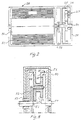
- Fig. 1a designates a piston-cylinder device with a cylinder 2 and a piston 3 displaceable in the cylinder.
- the piston 3 is joined to a piston rod 4, which extends through an opening 5 in one end wall 6 of the cylinder 2.
- the end wall also has a ventilation opening 7.
- the opposite end wall 8 of the cylinder 2 and the piston 3 delimit an expansion chamber 9, in which a pyrotechnic charge 10 with a detonator is placed.
- the charge 10 is designed to be exploded by retardation-sensitive means, which are known per se and not shown in more detail here.
- the cylinder wall in the area of the expansion chamber 9 is made with an opening 11 leading to a valve device 12, through which propellant gas in the expansion chamber can be led out to the environment.
- the valve device 12 (Fig. 1b) has a valve slide 14 displaceable in a housing 13, joined to a rotatable set screw 15 in a threaded bore 16 in the housing.
- the set screw 15 is rotatable with the aid of a servomotor 17, which is controlled by an electronic control unit 18 as a function of signals, firstly, from a weight-sensitive sensor 19, which can be built in to the weight-bearing portion of the vehicle seat (not shown) to register the weight of the person sitting in the seat, and secondly, from a so-called roll-over sensor 20 which senses if the vehicle is about to end up upside-down.
- the sensors 19 and 20 cooperating with the control unit 18 are activated, and the control unit 18, via the servomotor 17, sets the valve slide 14 to a position which is calculated to provide the optimal catch sequence for the occupant.
- the relationship between the occupant's weight and the size of the valve opening can be determined by tests and be stored in the control unit. In general, the valve opening is less the higher the weight. If the "roll-over sensor" indicates that the vehicle is about to end up up-side-down, the control unit 18 closes the valve 12, so that the reel mechanism 28 will be fixed in its pretensioning position by blocking the piston 3.
- the lack of a piston rod opening in the expansion chamber 9 assures that gas cannot leak out and change the position of the piston.
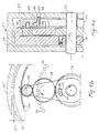
- Fig. 2 shows the planetary gear set 27 and the reel mechanism 28.
- the latter is of a type known per se and has a belt bobbin 30 with a belt web 31 wound up on the bobbin.
- the bobbin has a shaft 32 which, via a web jerk and compartment retardation sensitive retractor mechanism 33 (indicated only schematically here), is joined to a shaft 34 of the planetary gear set 27, which is shown in more detail in Fig. 3a, 3b, 4a and 4b.
- the shaft 34 is rotatably mounted in a housing 35, which is solidly joined, or made in one piece with the housing in which the bobbin shaft 32 is mounted. The housing 35 is thus solidly mounted in the vehicle.
- the planetary gear set shaft 34 carries a sun gear 36, engaging first planet gears 38 carried by a planet carrier 27.
- the planet gears 38 engage second planet gears 39 carried by a second planet carrier.
- the second planet gears 39 engage in turn a toothed rim 40 on the interior of the drum 26, which thus forms the ring gear of the planetary gear set 27.
- first blocking means in the form of a spring 41 loaded-pin 42 in the end wall of the drum.
- the pin 42 extends into a cavity 43 in the sun gear 36, and thus the ring gear 40 and consequently also the drum can be locked to the sun gear 36 (Figs. 3a and 3b).
- the starting position is the position shown in Figs. 3a and 3b, i.e. the pin 42 locks the sun gear 36 to the ring gear 40, which means a gear ratio of 1:1 between the shaft 34 and the drum 26.
- the pin 42 is kept in the position shown by a cylindrical body 47, which is held in an arcuate groove 48 in the end wall of the drum.
- the retractor mechanism 33 will lock together the shaft 32 of the bobbin and the planetary gear set 34 at the same as the charge 10 in the cylinder expansion chamber 9 is detonated.
- the cable 25, which is joined to and is somewhat wound up on the drum, will now turn the drum an angle which is dependent on the length of stroke of the piston 3 and the diameter of the drum 26.
- the belt web 31 is now pretensioned so that the slack of the web windings on the bobbin 30 is taken up and the belt is tightened against the occupant, the tightening sequence being determined by the setting of the valve 12.
- the torque will be transmitted from the sun gear 36 to the planet gears 38 and 39 and to the planet gear carrier 37, prompting an initial relative movement between the first planet gear 38 and the planet gear carrier 37.
- the pin 45 which during the pretensioning stage was kept with its end inserted into a flanked depression 49 in the first planet gear 38 under the force of the snap-spring 44, will now be pressed towards the planet gear carrier 37, which is provided, along a circle directly opposite the pin, with a plurality of uniformly spaced depressions 46.
- the snap-spring 44 will snap the opposite end of the pin into one of these depressions 46 so that the planet gear carrier 37 will be locked to the housing 35.
- the belt displacement as a function of time for one embodiment of the device according to the invention is illustrated in the diagram in Fig. 6.
- the belt during the pretensioning phase, is pulled in up to 5 cm in circa 15 ms and that the belt is thereafter fed out, during the force-limiting phase, 45 cm in circa 75 ms, which means that the entire belt displacement process takes circa 90 ms and that the gear ratio in the planetary gear set is circa 9:1, if the diameter of the drum and the medium diameter of the fed out web windings from the bobbin are approximately equal.
- the gear set has a housing 50, in which a first shaft 51 is rotatably mounted.
- the shaft 51 carries a planet gear carrier 52, on which first and second planet gears 53 and 54, solidly joined to each other, are mounted.
- a first ring gear 55 disposed on the inside of a drum 56 joined to the cable 25, is joined to a second shaft 57 mounted in the housing.
- the first ring gear 55 engages the first planet gears 53.
- a second ring gear 58 engages the second planet gears 54 and is joined to a sleeve 59, which is mounted concentrically in the housing with the first shaft 51, which is connectable to the belt bobbin shaft with the aid of a belt jerk and passenger compartment retardation-sensitive retractor mechanism (not shown in more detail here).
- blocking means which can be one-way clutches, sawtooth blocking mechanisms or snap-locks of a type known per se
- the first shaft 51 can be locked relative to the second shaft 57 to establish a gear ratio of 1:1
- the second ring gear 58 can be locked to the housing 50, while the shafts 51 and 57 are released relative to each other, thus providing a high gear ratio between the shafts 51 and 57.
- the invention makes possible precision adaption of the catching phase to the weight of the occupant, both during the pretensioning of the belt and force-limiting during the subsequent belt feed-out.
- the possibility of having a long belt feed-out makes it possible to optimize the force-limiting phase.
- the arrangement makes possible a roll-over function by virtue of the fact that the valve can be closed after the pretensioning phase so that the occupant is held securely in his seat.
Landscapes
- Engineering & Computer Science (AREA)
- Mechanical Engineering (AREA)
- Automotive Seat Belt Assembly (AREA)
- Retarders (AREA)
Applications Claiming Priority (2)
| Application Number | Priority Date | Filing Date | Title |
|---|---|---|---|
| SE0003681A SE517378C2 (sv) | 2000-10-12 | 2000-10-12 | Säkerhetsbältesförsträckare |
| SE0003681 | 2000-10-12 |
Publications (3)
| Publication Number | Publication Date |
|---|---|
| EP1197403A2 true EP1197403A2 (de) | 2002-04-17 |
| EP1197403A3 EP1197403A3 (de) | 2004-03-03 |
| EP1197403B1 EP1197403B1 (de) | 2005-09-07 |
Family
ID=20281387
Family Applications (1)
| Application Number | Title | Priority Date | Filing Date |
|---|---|---|---|
| EP01850167A Expired - Lifetime EP1197403B1 (de) | 2000-10-12 | 2001-10-10 | Gurtstraffer und Kraftbegrenzer |
Country Status (4)
| Country | Link |
|---|---|
| US (1) | US6547282B2 (de) |
| EP (1) | EP1197403B1 (de) |
| DE (1) | DE60113207T2 (de) |
| SE (1) | SE517378C2 (de) |
Families Citing this family (2)
| Publication number | Priority date | Publication date | Assignee | Title |
|---|---|---|---|---|
| GB0329164D0 (en) * | 2003-12-17 | 2004-01-21 | Britax Roemer Kindersicherheit Gmbh | Belt tension indicator |
| CN102729947B (zh) * | 2011-04-02 | 2014-11-26 | 苏州益高电动车辆制造有限公司 | 五点式安全带及安全带解锁机构 |
Citations (2)
| Publication number | Priority date | Publication date | Assignee | Title |
|---|---|---|---|---|
| DE3817942A1 (de) | 1988-05-27 | 1989-11-30 | Diehl Gmbh & Co | Verfahren und rueckstrahlortungsanlage zum aufsuchen von gegenstaenden an der meeresoberflaeche |
| DE29612781U1 (de) | 1996-07-23 | 1996-11-21 | Trw Repa Gmbh | Pyrotechnische Linearantriebseinrichtung für einen Gurtstraffer |
Family Cites Families (5)
| Publication number | Priority date | Publication date | Assignee | Title |
|---|---|---|---|---|
| US5873599A (en) * | 1997-05-13 | 1999-02-23 | Trw Vehicle Safety Systems Inc. | Apparatus for pretensioning seat belt webbing |
| US5871236A (en) * | 1997-05-13 | 1999-02-16 | Trw Vehicle Safety Systems Inc. | Apparatus for pretensioning seat belt webbing |
| US6039353A (en) * | 1997-12-24 | 2000-03-21 | Trw Vehicle Safety Systems Inc. | Apparatus for pretensioning seat belt webbing |
| US5947514A (en) * | 1998-02-20 | 1999-09-07 | Breed Automotive Technology, Inc. | Valve controlled automotive pyrotechnic systems |
| JPH11247906A (ja) * | 1998-03-04 | 1999-09-14 | Tokai Rika Co Ltd | クラッチ機構及びウエビング巻取装置 |
-
2000
- 2000-10-12 SE SE0003681A patent/SE517378C2/sv not_active IP Right Cessation
-
2001
- 2001-10-10 EP EP01850167A patent/EP1197403B1/de not_active Expired - Lifetime
- 2001-10-10 DE DE60113207T patent/DE60113207T2/de not_active Expired - Lifetime
- 2001-10-12 US US09/682,751 patent/US6547282B2/en not_active Expired - Lifetime
Patent Citations (2)
| Publication number | Priority date | Publication date | Assignee | Title |
|---|---|---|---|---|
| DE3817942A1 (de) | 1988-05-27 | 1989-11-30 | Diehl Gmbh & Co | Verfahren und rueckstrahlortungsanlage zum aufsuchen von gegenstaenden an der meeresoberflaeche |
| DE29612781U1 (de) | 1996-07-23 | 1996-11-21 | Trw Repa Gmbh | Pyrotechnische Linearantriebseinrichtung für einen Gurtstraffer |
Also Published As
| Publication number | Publication date |
|---|---|
| EP1197403B1 (de) | 2005-09-07 |
| SE517378C2 (sv) | 2002-06-04 |
| DE60113207T2 (de) | 2006-03-23 |
| US6547282B2 (en) | 2003-04-15 |
| EP1197403A3 (de) | 2004-03-03 |
| DE60113207D1 (de) | 2005-10-13 |
| SE0003681L (sv) | 2002-04-13 |
| SE0003681D0 (sv) | 2000-10-12 |
| US20020056983A1 (en) | 2002-05-16 |
Similar Documents
| Publication | Publication Date | Title |
|---|---|---|
| US5667161A (en) | Belt tensioner for safety belts for motor vehicles | |
| US5553803A (en) | Belt tensioner for safety belts for motor vehicles | |
| US5839686A (en) | Chain driven pretensioner and retractor | |
| US6505790B2 (en) | Pretensioner device | |
| US6343522B1 (en) | Gear mechanism and webbing retractor | |
| US5782423A (en) | Spiral tube compact pretensioner and retractor | |
| EP0641691A1 (de) | Sicherheitsgurt-Strammvorrichtung | |
| JP3436432B2 (ja) | 逆戻り防止装置 | |
| JP2003521417A (ja) | シートベルトプリテンショナ | |
| EP2716507A1 (de) | Sitzgurteinzug | |
| US5699976A (en) | Gear mechanism and pretensioner | |
| US20050156075A1 (en) | Helical pretensioner | |
| EP1201513B1 (de) | Weich-Start- Betätigungskolben | |
| EP1197404B1 (de) | Gurtstraffer und Kraftbegrenzer | |
| JP2020132144A (ja) | リトラクタプリテンショナアセンブリ | |
| EP1675759B1 (de) | Gurtbandspulenspannvorrichtung | |
| US20080290203A1 (en) | Electromechanical seat belt retractor | |
| EP1197403B1 (de) | Gurtstraffer und Kraftbegrenzer | |
| ES2081006T3 (es) | Dispositivo tensor para tensar un cinturon de seguridad en un automovil. | |
| EP0940603B1 (de) | Gurtaufroller | |
| JP4031135B2 (ja) | シートベルト装置 | |
| GB2326623A (en) | Pretensioner and comfort device driven by two ratio epicyclic gear. | |
| JPH10278738A (ja) | 3点式シートベルト装置 | |
| JPH01240345A (ja) | シートベルト巻込装置 | |
| JP2001260811A (ja) | ウェビング巻取装置及び車両 |
Legal Events
| Date | Code | Title | Description |
|---|---|---|---|
| PUAI | Public reference made under article 153(3) epc to a published international application that has entered the european phase |
Free format text: ORIGINAL CODE: 0009012 |
|
| AK | Designated contracting states |
Kind code of ref document: A2 Designated state(s): AT BE CH CY DE DK ES FI FR GB GR IE IT LI LU MC NL PT SE TR |
|
| AX | Request for extension of the european patent |
Free format text: AL;LT;LV;MK;RO;SI |
|
| PUAL | Search report despatched |
Free format text: ORIGINAL CODE: 0009013 |
|
| AK | Designated contracting states |
Kind code of ref document: A3 Designated state(s): AT BE CH CY DE DK ES FI FR GB GR IE IT LI LU MC NL PT SE TR |
|
| AX | Request for extension of the european patent |
Extension state: AL LT LV MK RO SI |
|
| 17P | Request for examination filed |
Effective date: 20040826 |
|
| AKX | Designation fees paid |
Designated state(s): DE FR GB |
|
| GRAP | Despatch of communication of intention to grant a patent |
Free format text: ORIGINAL CODE: EPIDOSNIGR1 |
|
| GRAS | Grant fee paid |
Free format text: ORIGINAL CODE: EPIDOSNIGR3 |
|
| GRAA | (expected) grant |
Free format text: ORIGINAL CODE: 0009210 |
|
| AK | Designated contracting states |
Kind code of ref document: B1 Designated state(s): DE FR GB |
|
| REG | Reference to a national code |
Ref country code: GB Ref legal event code: FG4D |
|
| PGFP | Annual fee paid to national office [announced via postgrant information from national office to epo] |
Ref country code: FR Payment date: 20051006 Year of fee payment: 5 |
|
| REF | Corresponds to: |
Ref document number: 60113207 Country of ref document: DE Date of ref document: 20051013 Kind code of ref document: P |
|
| PLBE | No opposition filed within time limit |
Free format text: ORIGINAL CODE: 0009261 |
|
| STAA | Information on the status of an ep patent application or granted ep patent |
Free format text: STATUS: NO OPPOSITION FILED WITHIN TIME LIMIT |
|
| 26N | No opposition filed |
Effective date: 20060608 |
|
| PG25 | Lapsed in a contracting state [announced via postgrant information from national office to epo] |
Ref country code: FR Free format text: LAPSE BECAUSE OF FAILURE TO SUBMIT A TRANSLATION OF THE DESCRIPTION OR TO PAY THE FEE WITHIN THE PRESCRIBED TIME-LIMIT Effective date: 20061020 |
|
| EN | Fr: translation not filed | ||
| PGFP | Annual fee paid to national office [announced via postgrant information from national office to epo] |
Ref country code: DE Payment date: 20141015 Year of fee payment: 14 Ref country code: GB Payment date: 20141015 Year of fee payment: 14 |
|
| REG | Reference to a national code |
Ref country code: DE Ref legal event code: R119 Ref document number: 60113207 Country of ref document: DE |
|
| GBPC | Gb: european patent ceased through non-payment of renewal fee |
Effective date: 20151010 |
|
| PG25 | Lapsed in a contracting state [announced via postgrant information from national office to epo] |
Ref country code: DE Free format text: LAPSE BECAUSE OF NON-PAYMENT OF DUE FEES Effective date: 20160503 Ref country code: GB Free format text: LAPSE BECAUSE OF NON-PAYMENT OF DUE FEES Effective date: 20151010 |