EP1197323A1 - Metal felt laminate structures - Google Patents
Metal felt laminate structures Download PDFInfo
- Publication number
- EP1197323A1 EP1197323A1 EP01124157A EP01124157A EP1197323A1 EP 1197323 A1 EP1197323 A1 EP 1197323A1 EP 01124157 A EP01124157 A EP 01124157A EP 01124157 A EP01124157 A EP 01124157A EP 1197323 A1 EP1197323 A1 EP 1197323A1
- Authority
- EP
- European Patent Office
- Prior art keywords
- metallic felt
- felt layer
- laminate
- layers
- metallic
- Prior art date
- Legal status (The legal status is an assumption and is not a legal conclusion. Google has not performed a legal analysis and makes no representation as to the accuracy of the status listed.)
- Withdrawn
Links
- 229910052751 metal Inorganic materials 0.000 title claims abstract description 55
- 239000002184 metal Substances 0.000 title claims abstract description 55
- 238000013016 damping Methods 0.000 claims abstract description 12
- 239000000835 fiber Substances 0.000 claims description 13
- 229910052782 aluminium Inorganic materials 0.000 claims description 6
- XAGFODPZIPBFFR-UHFFFAOYSA-N aluminium Chemical compound [Al] XAGFODPZIPBFFR-UHFFFAOYSA-N 0.000 claims description 6
- 239000010935 stainless steel Substances 0.000 claims description 5
- 229910001220 stainless steel Inorganic materials 0.000 claims description 5
- 229910000975 Carbon steel Inorganic materials 0.000 claims description 3
- 239000010962 carbon steel Substances 0.000 claims description 3
- 238000009413 insulation Methods 0.000 abstract description 8
- 239000010410 layer Substances 0.000 description 70
- 239000012790 adhesive layer Substances 0.000 description 21
- 238000012360 testing method Methods 0.000 description 13
- 239000000463 material Substances 0.000 description 12
- 239000002131 composite material Substances 0.000 description 10
- 229910000831 Steel Inorganic materials 0.000 description 7
- 239000010959 steel Substances 0.000 description 7
- 238000000034 method Methods 0.000 description 6
- 239000000853 adhesive Substances 0.000 description 5
- 230000001070 adhesive effect Effects 0.000 description 5
- 238000010438 heat treatment Methods 0.000 description 5
- ORQBXQOJMQIAOY-UHFFFAOYSA-N nobelium Chemical compound [No] ORQBXQOJMQIAOY-UHFFFAOYSA-N 0.000 description 5
- 239000007787 solid Substances 0.000 description 5
- PXHVJJICTQNCMI-UHFFFAOYSA-N Nickel Chemical compound [Ni] PXHVJJICTQNCMI-UHFFFAOYSA-N 0.000 description 4
- 239000010960 cold rolled steel Substances 0.000 description 4
- 239000011859 microparticle Substances 0.000 description 4
- 230000004044 response Effects 0.000 description 4
- 238000004458 analytical method Methods 0.000 description 3
- 239000011247 coating layer Substances 0.000 description 3
- 238000010276 construction Methods 0.000 description 3
- 230000008569 process Effects 0.000 description 3
- 229920001651 Cyanoacrylate Polymers 0.000 description 2
- XEEYBQQBJWHFJM-UHFFFAOYSA-N Iron Chemical compound [Fe] XEEYBQQBJWHFJM-UHFFFAOYSA-N 0.000 description 2
- HCHKCACWOHOZIP-UHFFFAOYSA-N Zinc Chemical compound [Zn] HCHKCACWOHOZIP-UHFFFAOYSA-N 0.000 description 2
- 239000000956 alloy Substances 0.000 description 2
- 229910045601 alloy Inorganic materials 0.000 description 2
- 230000000712 assembly Effects 0.000 description 2
- 238000000429 assembly Methods 0.000 description 2
- 239000000919 ceramic Substances 0.000 description 2
- 238000005516 engineering process Methods 0.000 description 2
- 238000009950 felting Methods 0.000 description 2
- 239000012212 insulator Substances 0.000 description 2
- 229920000554 ionomer Polymers 0.000 description 2
- 150000002739 metals Chemical class 0.000 description 2
- 238000012986 modification Methods 0.000 description 2
- 230000004048 modification Effects 0.000 description 2
- 229910052759 nickel Inorganic materials 0.000 description 2
- 229920000728 polyester Polymers 0.000 description 2
- 229920000642 polymer Polymers 0.000 description 2
- -1 polypropylene Polymers 0.000 description 2
- 238000003466 welding Methods 0.000 description 2
- 229910052725 zinc Inorganic materials 0.000 description 2
- 239000011701 zinc Substances 0.000 description 2
- 241001470502 Auzakia danava Species 0.000 description 1
- 229910001018 Cast iron Inorganic materials 0.000 description 1
- 229920000459 Nitrile rubber Polymers 0.000 description 1
- 239000004743 Polypropylene Substances 0.000 description 1
- 239000004830 Super Glue Substances 0.000 description 1
- 229920003182 Surlyn® Polymers 0.000 description 1
- 230000001133 acceleration Effects 0.000 description 1
- NIXOWILDQLNWCW-UHFFFAOYSA-N acrylic acid group Chemical group C(C=C)(=O)O NIXOWILDQLNWCW-UHFFFAOYSA-N 0.000 description 1
- 239000003522 acrylic cement Substances 0.000 description 1
- 239000010425 asbestos Substances 0.000 description 1
- 230000004888 barrier function Effects 0.000 description 1
- 238000005452 bending Methods 0.000 description 1
- 230000003197 catalytic effect Effects 0.000 description 1
- 239000011248 coating agent Substances 0.000 description 1
- 238000000576 coating method Methods 0.000 description 1
- 238000001816 cooling Methods 0.000 description 1
- 239000012792 core layer Substances 0.000 description 1
- 238000005260 corrosion Methods 0.000 description 1
- 230000007797 corrosion Effects 0.000 description 1
- 238000006073 displacement reaction Methods 0.000 description 1
- 238000002474 experimental method Methods 0.000 description 1
- 239000004744 fabric Substances 0.000 description 1
- 229920001821 foam rubber Polymers 0.000 description 1
- 239000011521 glass Substances 0.000 description 1
- 238000007731 hot pressing Methods 0.000 description 1
- 230000006872 improvement Effects 0.000 description 1
- 229920000592 inorganic polymer Polymers 0.000 description 1
- 238000007689 inspection Methods 0.000 description 1
- 239000012774 insulation material Substances 0.000 description 1
- 230000003993 interaction Effects 0.000 description 1
- 229910052742 iron Inorganic materials 0.000 description 1
- 238000004519 manufacturing process Methods 0.000 description 1
- 239000000203 mixture Substances 0.000 description 1
- 239000002245 particle Substances 0.000 description 1
- 235000013824 polyphenols Nutrition 0.000 description 1
- 229920001155 polypropylene Polymers 0.000 description 1
- 229920001296 polysiloxane Polymers 0.000 description 1
- 230000001105 regulatory effect Effects 0.000 description 1
- 229920005989 resin Polymers 0.000 description 1
- 239000011347 resin Substances 0.000 description 1
- 229910052895 riebeckite Inorganic materials 0.000 description 1
- 125000006850 spacer group Chemical group 0.000 description 1
- 239000004753 textile Substances 0.000 description 1
- 239000003190 viscoelastic substance Substances 0.000 description 1
- 210000002268 wool Anatomy 0.000 description 1
Images


Classifications
-
- F—MECHANICAL ENGINEERING; LIGHTING; HEATING; WEAPONS; BLASTING
- F16—ENGINEERING ELEMENTS AND UNITS; GENERAL MEASURES FOR PRODUCING AND MAINTAINING EFFECTIVE FUNCTIONING OF MACHINES OR INSTALLATIONS; THERMAL INSULATION IN GENERAL
- F16L—PIPES; JOINTS OR FITTINGS FOR PIPES; SUPPORTS FOR PIPES, CABLES OR PROTECTIVE TUBING; MEANS FOR THERMAL INSULATION IN GENERAL
- F16L59/00—Thermal insulation in general
- F16L59/02—Shape or form of insulating materials, with or without coverings integral with the insulating materials
- F16L59/029—Shape or form of insulating materials, with or without coverings integral with the insulating materials layered
-
- B—PERFORMING OPERATIONS; TRANSPORTING
- B32—LAYERED PRODUCTS
- B32B—LAYERED PRODUCTS, i.e. PRODUCTS BUILT-UP OF STRATA OF FLAT OR NON-FLAT, e.g. CELLULAR OR HONEYCOMB, FORM
- B32B15/00—Layered products comprising a layer of metal
- B32B15/14—Layered products comprising a layer of metal next to a fibrous or filamentary layer
-
- G—PHYSICS
- G10—MUSICAL INSTRUMENTS; ACOUSTICS
- G10K—SOUND-PRODUCING DEVICES; METHODS OR DEVICES FOR PROTECTING AGAINST, OR FOR DAMPING, NOISE OR OTHER ACOUSTIC WAVES IN GENERAL; ACOUSTICS NOT OTHERWISE PROVIDED FOR
- G10K11/00—Methods or devices for transmitting, conducting or directing sound in general; Methods or devices for protecting against, or for damping, noise or other acoustic waves in general
- G10K11/16—Methods or devices for protecting against, or for damping, noise or other acoustic waves in general
- G10K11/162—Selection of materials
- G10K11/168—Plural layers of different materials, e.g. sandwiches
-
- Y—GENERAL TAGGING OF NEW TECHNOLOGICAL DEVELOPMENTS; GENERAL TAGGING OF CROSS-SECTIONAL TECHNOLOGIES SPANNING OVER SEVERAL SECTIONS OF THE IPC; TECHNICAL SUBJECTS COVERED BY FORMER USPC CROSS-REFERENCE ART COLLECTIONS [XRACs] AND DIGESTS
- Y10—TECHNICAL SUBJECTS COVERED BY FORMER USPC
- Y10T—TECHNICAL SUBJECTS COVERED BY FORMER US CLASSIFICATION
- Y10T428/00—Stock material or miscellaneous articles
- Y10T428/12—All metal or with adjacent metals
- Y10T428/12424—Mass of only fibers
-
- Y—GENERAL TAGGING OF NEW TECHNOLOGICAL DEVELOPMENTS; GENERAL TAGGING OF CROSS-SECTIONAL TECHNOLOGIES SPANNING OVER SEVERAL SECTIONS OF THE IPC; TECHNICAL SUBJECTS COVERED BY FORMER USPC CROSS-REFERENCE ART COLLECTIONS [XRACs] AND DIGESTS
- Y10—TECHNICAL SUBJECTS COVERED BY FORMER USPC
- Y10T—TECHNICAL SUBJECTS COVERED BY FORMER US CLASSIFICATION
- Y10T428/00—Stock material or miscellaneous articles
- Y10T428/12—All metal or with adjacent metals
- Y10T428/12444—Embodying fibers interengaged or between layers [e.g., paper, etc.]
Definitions
- This invention relates to laminate structures, and more particularly, to laminate structures that have thermal insulation and vibration damping properties and structures incorporating the laminates therein.
- laminate structures having insulation material between outer metal skin layers have been used to provide thermal insulation and vibration and noise control in a variety of applications.
- These laminates typically includes two outer metal layers and an interior layer of ceramic, glass cloth or asbestos.
- An important feature of the invention is the provision of a laminate which is of a relatively simple and economical construction.
- a still further feature of the invention is the provision of a laminate of the type set forth, which is lightweight and provides vibration and noise damping properties and acts as a thermal insulator.
- a further feature of the invention is the provision of a laminate of the type set forth, layers of which can be welded together, and which laminate can be welded to another structure.
- Yet another feature of the invention is the provision of a brake shoe assembly including a damper formed of the laminate which aids in reducing vibration and noise in use.
- Another feature of the invention is the provision of tubing formed of the laminate, which may be used in various automotive and other applications.
- Yet another feature of the present invention is the provision of a brake rotor formed with a metal felt core layer which provides noise and vibration damping properties.
- Certain ones of these and other features of the invention may be attained by providing a laminate including first and second metal layers respectively having first and second interior surfaces, and a metallic felt layer attached to and disposed over the majority of each of the first and second interior surfaces.
- the laminate 20 includes two metal layers 22, 24, respectively having interior surfaces 26, 28 and exterior surfaces 30, 32. As seen in FIG. 2, the interior surfaces 26, 28 respectively have adhesive layers 34, 36 disposed thereon. Disposed between the adhesive layers 34 and 36 is a metallic felt layer 38. As seen in FIG. 1, the metallic felt layer 38 is preferably disposed over substantially the entire surface area of both of the interior surfaces 26, 28.
- the metal layers 22 and 24 can be formed of any of many metals, including aluminum, stainless steel and cold rolled steel, and each may have a thickness of from about 0.010 inch to about 0.060 inch.
- the metallic felt layer 38 can be formed of a variety of metallic felts, including those made of stainless steel, carbon steel and aluminum. These metallic felts preferably have a mean fiber width of from about 40 to about 120 ⁇ m.
- the metallic felt layer 38 may also include up to about 10% by weight of a polymeric fiber, such as polyester, or polypropylene.
- the metallic felt layer 38 also may have a basis weight of from about 400 to about 1600 g/m 2 .
- a preferred metallic felt layer 38 is one formed of a metallic felt sold by Global Material Technologies, Inc. under the designation SSW-Poly Metric Type CMX textile with 10% polyester fiber by weight.
- Metallic felts are widely known.
- Generally metallic felt is a mat of metal fibers (not unlike steel wool) which has undergone a felting process.
- the felting process increases the density of the matting with a series of rollers.
- the three-dimensional strength and cohesion of the material is increased by a series of needling devices. These needling devices punch through the thickness of the mat from the top and bottom, pulling fibers with them and causing the fibers to intertwine with one another.
- the intertwined fibers give the material greater tensile strength in all directions.
- the adhesive layers 34, 36 may be formed of a polymeric adhesive, e.g. a film of an ionomer resin such as Surlyn Ionomer made by E.I. DuPont de Nemours, or a preceramic adhesive, such as one sold under the designation Ceraset SN Inorganic Polymer by Commodore Polymer Technologies, Inc. Such a preceramic adhesive is capable of maintaining a bond between the metallic felt layer 38 and the metal layers 22, 24 at temperatures exceeding 1200°F.
- the adhesive layers 34, 36 may also include electrically conductive microparticles, such as iron, zinc, nickel, aluminum or their alloys, to improve conduction through the adhesive layers 34, 36 to boost weld quality.
- the micro particles may have a mean diameter of from about 0.0005 inch to 0.002 inch.
- laminates 20a and 20b are similar to laminate 20 but without the adhesive layers 34, 36.
- laminate 20a includes the metal layers 22, 24 welded to the metallic felt layer 38.
- laminate 20b includes the metal layers 22, 24 riveted, or otherwise mechanically fastened, to the metallic felt layer 38 by a series of rivets 40 or other suitable fasteners. Alternating, self-fastening systems could be used.
- the laminates 20, 20a, 20b serve as effective thermal barriers and can be used in a variety of products, including automotive heat shields and muffler wraps.
- the laminates 20, 20a, 20b can be formed into finished parts by conventional sheet forming techniques.
- the laminates 20, 20a, 20b could be respectively formed by stacking the individual layers and hot pressing the structure, by welding the structures or by mechanically fastening the layers.
- conventional continuous coil to coil manufacturing methods may be used for providing larger volumes of laminate.
- the finished laminates may be collected and stored in a roll form.
- the laminates can also be used to form tubing, such as that used for automotive exhaust systems.
- an automotive exhaust system 42 is illustrated.
- the automotive exhaust system 42 includes an exhaust pipe 44 connecting a muffler 46 to a catalytic converter 48 in a known manner.
- the exhaust pipe 44 is formed of tubing 45 including inner and outer metal layers 50, 52, respectively having interior surfaces 54, 56 and exposed surfaces 58, 60.
- the interior surfaces 54, 56 respectively have adhesive layers 62, 64 disposed thereon.
- a metallic felt layer 66 Disposed between the adhesive layers 62, 64 is a metallic felt layer 66.
- the metal layers 50, 52 can be formed of the same materials as layers 22 and 24. Each may have a thickness of from about 0.005 inch to about 0.060 inch.
- the exposed surface 60 of the outer metal layer 52 can have a corrosion resistant metallic coating, such as aluminum or zinc.
- the adhesive layers 62, 64 can be formed of the same materials as adhesive layers 34, 36 and can include electrically conductive microparticles, as necessary.
- the metallic felt layer 66 can also be formed of the same materials as the metallic felt layer 38.
- the outer metal layer may have an outside diameter of from about 1.5 inches to about 2.5 inches.
- the inner metal layer 58 can have an outside diameter of from about 1.0 inches to about 2 inches. As discussed below, the tubing 45 provides thermal insulation and sound damping properties.
- tubing 45a is shown which is substantially identical to tubing 45, except that the inner metal layer 50 has a plurality of perforations 68 to allow exhaust gas to pass through to the metallic felt layer 66 for the purpose of aiding sound dissipation.
- tubing 45 and 45a in FIGS. 6 and 7 have adhesive layers 62, 64, either tubing may be formed without these layers. Thus, the tubing could be held together by frictional forces between the metallic felt layer 66 and the inner and outer metal layers 50, 52.
- the tubing 45 may be formed in a conventional tube mill with any of the laminates 20, 20a, 20b.
- strips of laminate 20 may be fed directly to the tube mill, and progressively rolled into a tube and seam welded shut.
- the same process may be used with laminates, similar to laminate 20, except that the adhesive layers 34, 36 do not extend to the edges of the metal layer 22 of adhesive materials so as to improve the weld quality.
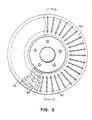
- an automotive brake system 70 for one wheel includes a rotor 72, a caliper 74 and a pair of brake shoe assemblies 76 (one shown).
- the rotor 72 includes two generally parallel annular disks 78, 80 separated by and connected to a plurality of cooling blades 82.
- Each disk 78, 80 has a metallic felt, flat, annular layer 84 disposed within a solid metal portion 86 formed from a metal, such as cast iron, steel, nickel-based alloy or composite materials.
- the metallic felt layer 84 can be formed of any of the metallic felts discussed above.
- the brake shoe assembly 76 includes a conventional brake pad 88 for frictionally engaging a disk (78 or 80).
- the brake pad 88 is coupled to a backing plate 90 in a known manner.
- the backing plate 90 has a rotor-facing side 92 and an exterior side 94.
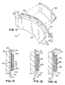
- the brake shoe assembly 76 also includes a brake damper 96 coupled to the exterior side 94 of the backing plate 90 and which includes one or more metallic felt layers.
- FIG. 12 shows a first brake damper 96a which includes a metallic felt layer 98 having first and second sides 100, 102 respectively coupled to the exterior side 94 of the backing plate 90 and a metal layer 104 by adhesive layers 106, 108.
- the metal layer 104 also has an exterior surface 110 covered by a exterior coating layer 112.
- FIG. 13 shows an alternative brake damper 96b coupled to the backing plate 90.
- the brake damper 96b includes a first metal layer 114 coupled to the backing plate 90 by an adhesive layer 116 and to a metallic felt layer 118 by another adhesive layer 120.
- the metallic felt layer 118 is coupled by an adhesive layer 121 to another metal layer 122 having an exterior surface with an exterior coating layer 124.
- FIG. 14 shows a third brake damper 96c coupled to the backing plate 90 including a first metal layer 126 welded to the backing plate 90 and to a metallic felt layer 128.
- the metallic felt layer 128 is welded to a second metal layer 130, which is coupled to a layer 132, which is also coupled to a third metal layer 134 having an exterior surface 136 having an exterior coating layer 138.
- the metal layers 104, 114, 122, 126, 130 and 134 may be formed of the same metals as the metal layers 22, 24 of laminates discussed above. Each of the metal layers 104, 114, 122, 126, 130 and 134 may have a thickness of from about 0.009 inch to about 0.040 inch.
- the adhesive layers 106, 108, 116, 120 and 121 may also be formed of the same material as adhesive layers 34, 36 and may include electrically conductive particles, such as metal microparticles discussed above, to improve weldability.
- the adhesive layers 106, 108, 116, 120 and 121 are also preferably formed of a material that provides vibration damping properties. Additionally, one or more of the adhesive layers 106 and 116, may be removed, in which case the brake dampers 96a, 96b may be attached to the brake shoe 90 by welding. Additionally, the other adhesive layers 108, 120 and 121 may also be removed and the individual layers of the brake damper 96a and 96b may be welded together.
- the layer 132 may be a metallic felt layer formed of the same materials previously discussed or any of a number of viscoelastic materials, e.g., polymer adhesives, such as acrylic, nitrile rubbers, silicones, phenolics and mixtures thereof, which provides vibration damping properties.
- polymer adhesives such as acrylic, nitrile rubbers, silicones, phenolics and mixtures thereof, which provides vibration damping properties.
- a modified brake shoe assembly 76A which includes a backing plate 90A with a side 92A, to which is secured the conventional brake pad 88, and a side 94A.
- the backing plate 90A includes a core metallic felt layer 91 completely surrounded by a metal shell 93, which defines a layer 95 to which the brake pad 88 is attached and a layer 97 to which a shim/insulator 99 may optionally be attached.
- the core metallic felt layer 91 may be formed of the same material previously discussed.
- Laminates (samples 1 and 2) had the same construction as laminate 20, discussed above.
- a sample 3 consisting of 2 layers of steel separated by a 1/8" air gap created by five narrow spacers (1 ⁇ 8" wide x 8" long x 1 ⁇ 8" thick parallelly aligned and generally equally spaced) was also evaluated in the study for comparison. The tests measured the temperature drop through small panels exposed to a radiant heat source. The configurations of the test sample are listed in Table 1 below.
- the apparatus 100 includes a heating element 102 consisting of a 250-watt cylindrical cartridge heater (6" long x .75" dia.).
- a temperature controller operated on a constant manual power setting, regulated the power output to the heating element 102.
- the heating element 102 is enclosed on three sides with low density, ceramic firebrick 104.
- Four steel stands support the test sample 106, at each corner (two shown), with minimal contact area.
- a 6" x 8" stainless steel plate 108 is mounted 1" above the test sample 106 to create a somewhat enclosed environment like that of a typical exhaust pipe.
- the samples 106 were placed 1" above the heating element 102. The system was allowed to reach steady state and temperatures were recorded every 30 seconds for 30 minutes. The heating element 102 reached temperatures between 1200-1300°F which correspond to bottom side temperatures of 800-1050°F on the panel. Table 2 displays average steady state temperature drop through the samples. Average Steady State Temperatures Sample # Heater T (°F) Bottom T (°F) Top T (°F) ⁇ T (°F) 1 1220 1046 703 343 2 1271 971 622 327 3 1229 847 655 191
- the metallic felt laminate structures will provide excellent thermal insulation.
- the samples were tested as follows. A 4" wide x 8" long sample was placed inside a room-temperature oven on a foam rubber mat, which approximated a free boundary condition (to eliminate interaction with oven). An accelerometer, used to measure the acceleration of the sample over various frequencies, was bonded near the edge of each sample (1" from a first longitudinal end and at the center of the width of the sample) with an alkyl cyanoacrylate "super glue". The sample was then impacted five times with an impact hammer on the end of the sample opposite the accelerometer (1" from the second longitudinal end and at the center of the width of the sample.) The hammer used in this experiment was a Modally Tuned® hammer, with a 4" long handle and approximately a 0.025" diameter tip.
- the tip had a force transducer mounted behind it to measure the force upon impact.
- the accelerometer had an approximate diameter of 0.125" and was less than 1 oz. and was classified as lightweight.
- the force of the impacts, as well as the responses measured by the accelerometer, were recorded and averaged by a data analyzer (Star System v5.2 - Star Modal® ).
- the analyzer used the data to produce a frequency response curve, displaying compliance (displacement/force) vs. frequency. Different bending modes of the sample correspond to different peaks on the frequency response curve.
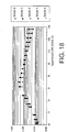
- a particular mode or frequency was selected (3 rd mode in the present case) and the composite loss factor was determined in a known manner and plotted vs. temperature as shown in FIG. 17.
- the laminates of the present invention have a substantially constant composite loss factor over a wide temperature range, which is substantially greater than the solid cold roll steel sample at each temperature tested.
- the viscoelastic laminate sample does not have a substantially constant composite loss factor over a wide temperature range. This is important because different systems operate at different temperature ranges, meaning that the viscoelastic laminates would not be useful for some systems, whereas the laminates of the present invention could be used on a wide range of systems.
- sample 6 and 7 were made in accordance with tubing 45 (FIG. 3). Samples 6-8 measured 1 ft. by 2.25" OD and had the following layers:
- FIG. 19 is a plot of the composite loss factors (for a predetermined frequency) vs. temperature for the 3 samples evaluated.
- the tubes with the metallic felt layers displayed significant damping improvement (had higher composite loss factors) over the solid steel tube throughout the entire temperature range.
- FIG. 19 also shows that the damping performance (or composite loss factor) of the metal felt tubing remained close to constant over the temperature range tested.
Landscapes
- Engineering & Computer Science (AREA)
- General Engineering & Computer Science (AREA)
- Physics & Mathematics (AREA)
- Acoustics & Sound (AREA)
- Multimedia (AREA)
- Mechanical Engineering (AREA)
- Laminated Bodies (AREA)
Abstract
Description
- This invention relates to laminate structures, and more particularly, to laminate structures that have thermal insulation and vibration damping properties and structures incorporating the laminates therein.
- In the past, laminate structures having insulation material between outer metal skin layers have been used to provide thermal insulation and vibration and noise control in a variety of applications. These laminates typically includes two outer metal layers and an interior layer of ceramic, glass cloth or asbestos.
- Many of these laminates suffered because the insulation layers were not weldable to the skins or the entire laminate was not weldable to another structure. This limits the flexibility of the use of these laminates with other structures and the ability to form the laminates into finished products, such as tubing. Many of the insulation layers of the laminates also did not have structural integrity, further limiting such laminates.
- It is a general object of the present invention to provide an improved laminate which avoids the disadvantages of prior laminates while affording additional structural and operational advantages.
- An important feature of the invention is the provision of a laminate which is of a relatively simple and economical construction.
- A still further feature of the invention is the provision of a laminate of the type set forth, which is lightweight and provides vibration and noise damping properties and acts as a thermal insulator.
- A further feature of the invention is the provision of a laminate of the type set forth, layers of which can be welded together, and which laminate can be welded to another structure. Yet another feature of the invention is the provision of a brake shoe assembly including a damper formed of the laminate which aids in reducing vibration and noise in use.
- Another feature of the invention is the provision of tubing formed of the laminate, which may be used in various automotive and other applications.
- Yet another feature of the present invention is the provision of a brake rotor formed with a metal felt core layer which provides noise and vibration damping properties.
- Certain ones of these and other features of the invention may be attained by providing a laminate including first and second metal layers respectively having first and second interior surfaces, and a metallic felt layer attached to and disposed over the majority of each of the first and second interior surfaces.
- The invention consists of certain novel features and a combination of parts hereinafter fully described, illustrated in the accompanying drawings, and particularly pointed out in the appended claims, it being understood that various changes in the details may be made without departing from the spirit, or sacrificing any of the advantages of the present invention.
- For the purpose of facilitating an understanding of the invention, there is illustrated in the accompanying drawings a preferred embodiment thereof, from an inspection of which, when considered in connection with the following description, the invention, its construction and operation, and many of its advantages should be readily understood and appreciated.
- FIG. 1 is a perspective view of a laminate of the present invention;
- FIG. 2 is an enlarged, fragmentary sectional view taken generally along the line 2-2 of FIG. 1;
- FIGS. 3 and 4 are sectional views, similar to FIG. 2, of alternate laminate embodiments;
- FIG. 5 is a top plan view of a motor vehicle exhaust system with portions broken away;
- FIG. 6 is an enlarged, fragmentary, sectional view taken generally along line 6-6 of FIG. 5;
- FIG. 7 is a view similar to FIG. 6 of an alternate tubing embodiment;
- FIG. 8 is a perspective view of a rotor and brake shoe assembly of the present invention, partially broken away;
- FIG. 9 is an enlarged, side elevational view of the rotor of FIG. 8 partially broken away;
- FIG. 10 is a sectional view taken generally along line 10-10 of FIG. 9;
- FIG. 11 is a perspective view of a brake shoe assembly, with the brake damper, shown in block form, exploded away from the remainder of the assembly;
- FIGS. 12-14 are schematic sectional views of brake shoe assemblies with different brake dampers attached to the backing plate;
- FIG. 15 is a schematic sectional view of another embodiment of brake shoe assembly;
- FIG. 16 is a schematic representation of the thermal testing equipment used to test the present invention and comparison samples; and
- FIGS. 17-19 are plots of composite loss factor versus temperature, based upon vibration testing of the products of the present invention and comparison samples.
-
- Referring to FIGS. 1 and 2, a
laminate 20 of the present invention is shown. Thelaminate 20 includes twometal layers interior surfaces exterior surfaces interior surfaces adhesive layers adhesive layers metallic felt layer 38. As seen in FIG. 1, themetallic felt layer 38 is preferably disposed over substantially the entire surface area of both of theinterior surfaces - The
metal layers metallic felt layer 38 can be formed of a variety of metallic felts, including those made of stainless steel, carbon steel and aluminum. These metallic felts preferably have a mean fiber width of from about 40 to about 120 µm. Themetallic felt layer 38 may also include up to about 10% by weight of a polymeric fiber, such as polyester, or polypropylene. Themetallic felt layer 38 also may have a basis weight of from about 400 to about 1600 g/m2. A preferredmetallic felt layer 38 is one formed of a metallic felt sold by Global Material Technologies, Inc. under the designation SSW-Poly Metric Type CMX textile with 10% polyester fiber by weight. - Metallic felts are widely known. Generally metallic felt is a mat of metal fibers (not unlike steel wool) which has undergone a felting process. The felting process increases the density of the matting with a series of rollers. At the same time, the three-dimensional strength and cohesion of the material is increased by a series of needling devices. These needling devices punch through the thickness of the mat from the top and bottom, pulling fibers with them and causing the fibers to intertwine with one another. The intertwined fibers give the material greater tensile strength in all directions.
- The
adhesive layers metallic felt layer 38 and themetal layers adhesive layers adhesive layers - As seen in FIGS. 3 and 4, laminates 20a and 20b are similar to
laminate 20 but without theadhesive layers metal layers metallic felt layer 38. In FIG. 4, laminate 20b includes themetal layers metallic felt layer 38 by a series ofrivets 40 or other suitable fasteners. Alternating, self-fastening systems could be used. - The
laminates 20, 20a, 20b serve as effective thermal barriers and can be used in a variety of products, including automotive heat shields and muffler wraps. Thelaminates 20, 20a, 20b can be formed into finished parts by conventional sheet forming techniques. - The
laminates 20, 20a, 20b could be respectively formed by stacking the individual layers and hot pressing the structure, by welding the structures or by mechanically fastening the layers. For providing larger volumes of laminate, conventional continuous coil to coil manufacturing methods may be used. The finished laminates may be collected and stored in a roll form. - The laminates can also be used to form tubing, such as that used for automotive exhaust systems. Referring to FIG. 5, an
automotive exhaust system 42 is illustrated. Theautomotive exhaust system 42 includes anexhaust pipe 44 connecting amuffler 46 to acatalytic converter 48 in a known manner. Referring to FIG. 6, theexhaust pipe 44 is formed oftubing 45 including inner andouter metal layers interior surfaces surfaces 58, 60. The interior surfaces 54, 56 respectively haveadhesive layers adhesive layers metallic felt layer 66. The metal layers 50, 52 can be formed of the same materials aslayers outer metal layer 52 can have a corrosion resistant metallic coating, such as aluminum or zinc. The adhesive layers 62, 64 can be formed of the same materials asadhesive layers metallic felt layer 66 can also be formed of the same materials as themetallic felt layer 38. The outer metal layer may have an outside diameter of from about 1.5 inches to about 2.5 inches. Theinner metal layer 58 can have an outside diameter of from about 1.0 inches to about 2 inches. As discussed below, thetubing 45 provides thermal insulation and sound damping properties. - As seen in FIG. 7,
tubing 45a is shown which is substantially identical totubing 45, except that theinner metal layer 50 has a plurality of perforations 68 to allow exhaust gas to pass through to themetallic felt layer 66 for the purpose of aiding sound dissipation. - Though the
tubing adhesive layers metallic felt layer 66 and the inner andouter metal layers - The
tubing 45 may be formed in a conventional tube mill with any of thelaminates 20, 20a, 20b. For example, strips oflaminate 20 may be fed directly to the tube mill, and progressively rolled into a tube and seam welded shut. Additionally, the same process may be used with laminates, similar tolaminate 20, except that theadhesive layers metal layer 22 of adhesive materials so as to improve the weld quality. - The metallic felt structures of the present invention can be utilized in automotive braking systems. Referring to FIGS. 8-10, an
automotive brake system 70 for one wheel includes arotor 72, acaliper 74 and a pair of brake shoe assemblies 76 (one shown). As seen in FIGS. 8 and 10, therotor 72 includes two generally parallelannular disks cooling blades 82. Eachdisk annular layer 84 disposed within a solid metal portion 86 formed from a metal, such as cast iron, steel, nickel-based alloy or composite materials. Themetallic felt layer 84 can be formed of any of the metallic felts discussed above. - As seen in FIG. 11, the
brake shoe assembly 76 includes aconventional brake pad 88 for frictionally engaging a disk (78 or 80). Thebrake pad 88 is coupled to abacking plate 90 in a known manner. Thebacking plate 90 has a rotor-facingside 92 and anexterior side 94. Thebrake shoe assembly 76 also includes abrake damper 96 coupled to theexterior side 94 of thebacking plate 90 and which includes one or more metallic felt layers. - FIG. 12 shows a first brake damper 96a which includes a
metallic felt layer 98 having first andsecond sides exterior side 94 of thebacking plate 90 and ametal layer 104 byadhesive layers metal layer 104 also has anexterior surface 110 covered by a exterior coating layer 112. - FIG. 13 shows an
alternative brake damper 96b coupled to thebacking plate 90. Thebrake damper 96b includes afirst metal layer 114 coupled to thebacking plate 90 by anadhesive layer 116 and to ametallic felt layer 118 by anotheradhesive layer 120. Themetallic felt layer 118 is coupled by anadhesive layer 121 to anothermetal layer 122 having an exterior surface with anexterior coating layer 124. - FIG. 14 shows a third brake damper 96c coupled to the
backing plate 90 including afirst metal layer 126 welded to thebacking plate 90 and to ametallic felt layer 128. Themetallic felt layer 128 is welded to asecond metal layer 130, which is coupled to alayer 132, which is also coupled to athird metal layer 134 having anexterior surface 136 having an exterior coating layer 138. - The metal layers 104, 114, 122, 126, 130 and 134 may be formed of the same metals as the metal layers 22, 24 of laminates discussed above. Each of the metal layers 104, 114, 122, 126, 130 and 134 may have a thickness of from about 0.009 inch to about 0.040 inch.
- The
adhesive layers adhesive layers adhesive layers adhesive layers brake dampers 96a, 96b may be attached to thebrake shoe 90 by welding. Additionally, the otheradhesive layers brake damper 96a and 96b may be welded together. - The
layer 132 may be a metallic felt layer formed of the same materials previously discussed or any of a number of viscoelastic materials, e.g., polymer adhesives, such as acrylic, nitrile rubbers, silicones, phenolics and mixtures thereof, which provides vibration damping properties. - Referring to FIG. 15, there is illustrated a modified brake shoe assembly 76A which includes a
backing plate 90A with aside 92A, to which is secured theconventional brake pad 88, and aside 94A. Thebacking plate 90A includes a coremetallic felt layer 91 completely surrounded by ametal shell 93, which defines alayer 95 to which thebrake pad 88 is attached and alayer 97 to which a shim/insulator 99 may optionally be attached. The coremetallic felt layer 91 may be formed of the same material previously discussed. - Tests were performed to quantify the thermal insulation values of different laminate structures (4" x 8" samples). Laminates (
samples 1 and 2) had the same construction aslaminate 20, discussed above. Asample 3, consisting of 2 layers of steel separated by a 1/8" air gap created by five narrow spacers (⅛" wide x 8" long x ⅛" thick parallelly aligned and generally equally spaced) was also evaluated in the study for comparison. The tests measured the temperature drop through small panels exposed to a radiant heat source. The configurations of the test sample are listed in Table 1 below.
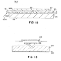
- This testing was carried out in testing apparatus depicted in Figure 16. The
apparatus 100 includes aheating element 102 consisting of a 250-watt cylindrical cartridge heater (6" long x .75" dia.). A temperature controller, operated on a constant manual power setting, regulated the power output to theheating element 102. Theheating element 102 is enclosed on three sides with low density,ceramic firebrick 104. Four steel stands support thetest sample 106, at each corner (two shown), with minimal contact area. A 6" x 8"stainless steel plate 108 is mounted 1" above thetest sample 106 to create a somewhat enclosed environment like that of a typical exhaust pipe. A type K thermocouple embedded in the heater, and additional thermocouples cemented on the top and bottom of eachtest sample 106, measured temperature during testing. Temperature data was recorded as a PC data file via an electronic data logger. The entire apparatus was contained in an insulated box, with access from the top side. - The
samples 106 were placed 1" above theheating element 102. The system was allowed to reach steady state and temperatures were recorded every 30 seconds for 30 minutes. Theheating element 102 reached temperatures between 1200-1300°F which correspond to bottom side temperatures of 800-1050°F on the panel. Table 2 displays average steady state temperature drop through the samples.Average Steady State Temperatures Sample # Heater T (°F) Bottom T (°F) Top T (°F) ΔT (°F) 1 1220 1046 703 343 2 1271 971 622 327 3 1229 847 655 191 - As seen by ΔT of
samples - In addition to measuring the thermal insulating ability of the laminates of the present invention, a study was also conducted to examine the metal felt structure's ability to damp vibrations or lessen noise.
- A laminate (sample 4) made in accordance with
laminate 20 of FIGS. 1 and 2 was tested vs. a solid 0.03" thick Cold Rolled Steel sample (sample 5). The samples consisted of the following layer materials: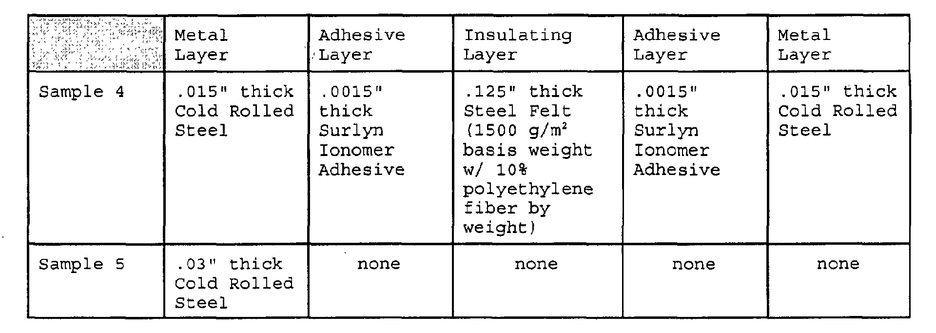
- The samples were tested as follows. A 4"
wide x 8" long sample was placed inside a room-temperature oven on a foam rubber mat, which approximated a free boundary condition (to eliminate interaction with oven). An accelerometer, used to measure the acceleration of the sample over various frequencies, was bonded near the edge of each sample (1" from a first longitudinal end and at the center of the width of the sample) with an alkyl cyanoacrylate "super glue". The sample was then impacted five times with an impact hammer on the end of the sample opposite the accelerometer (1" from the second longitudinal end and at the center of the width of the sample.) The hammer used in this experiment was a Modally Tuned® hammer, with a 4" long handle and approximately a 0.025" diameter tip. The tip had a force transducer mounted behind it to measure the force upon impact. The accelerometer had an approximate diameter of 0.125" and was less than 1 oz. and was classified as lightweight. The force of the impacts, as well as the responses measured by the accelerometer, were recorded and averaged by a data analyzer (Star System v5.2 - Star Modal® ). The analyzer used the data to produce a frequency response curve, displaying compliance (displacement/force) vs. frequency. Different bending modes of the sample correspond to different peaks on the frequency response curve. A particular mode or frequency was selected (3rd mode in the present case) and the composite loss factor was determined in a known manner and plotted vs. temperature as shown in FIG. 17. - The above procedure was repeated at 25°F intervals up to 300°F and the composite loss factors were then plotted vs. temperature (Figure 17). As seen in FIG. 17, the laminates of the present invention have a substantially constant composite loss factor over a wide temperature range, which is substantially greater than the solid cold roll steel sample at each temperature tested.
- For comparison, a laminate without metal felt formed of the following layers 0.020" thick cold rolled steel, .001" thick acrylic adhesive, 0.020" thick cold rolled steel was also tested by the same method, except that the sample was 1"
wide x 8" long. (It is believed that 4" x 8" samples would have behaved similarly.) As seen in FIG. 18, the viscoelastic laminate sample does not have a substantially constant composite loss factor over a wide temperature range. This is important because different systems operate at different temperature ranges, meaning that the viscoelastic laminates would not be useful for some systems, whereas the laminates of the present invention could be used on a wide range of systems. - The same vibration testing or modal analysis was done on two different prototype exhaust tubes (
samples 6 and 7) and was compared to a solid steel tube (sample 8).Samples 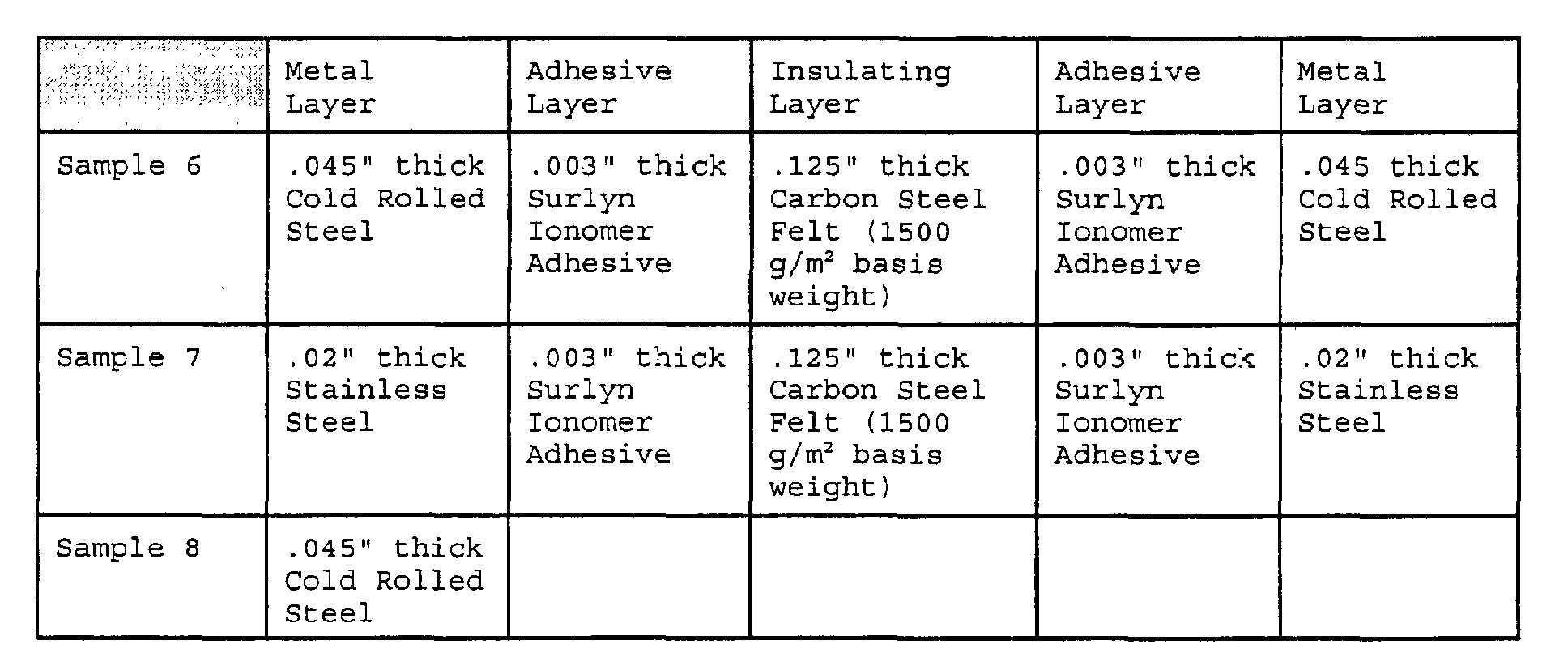
- The accelerometer, described above, was placed 1" from one longitudinal end of the tube and the impact hammer delivered blows 1" from the other longitudinal end of the tube. Like the vibration analysis of the laminates in Example 2, the analysis measured the frequency response of the pipes to mild impact over a specified temperature range (75 - 300°F) to determine the composite loss factor at each temperature for a predetermined frequency. FIG. 19 is a plot of the composite loss factors (for a predetermined frequency) vs. temperature for the 3 samples evaluated. As seen in FIG. 19, the tubes with the metallic felt layers displayed significant damping improvement (had higher composite loss factors) over the solid steel tube throughout the entire temperature range. FIG. 19 also shows that the damping performance (or composite loss factor) of the metal felt tubing remained close to constant over the temperature range tested.
- While particular embodiments of the present invention have been shown and described, it will be appreciated by those skilled in the art that changes and modifications may be made without departing from the invention in its broader aspects. Therefore, the aim in the appended claims is to cover all such changes and modifications as fall within the true spirit and scope of the invention. The matter set forth in the foregoing description and accompanying drawings is offered by way of illustration only and not as a limitation. The actual scope of the invention is intended to be defined in the following claims when viewed in their proper perspective based on the prior art.
Claims (28)
- A laminate comprising:first and second metal layers respectively having first and second interior surfaces; anda metallic felt layer attached to and disposed over the majority of each of the first and second interior surfaces.
- The laminate of claim 1, wherein the metallic felt layer is formed from a metal selected from the group consisting of stainless steel, carbon steel and aluminum.
- The laminate of claim 1, wherein the metallic felt has a basis weight in the range of from about 400 g/m2 to about 1600 g/m2.
- The laminate of claim 3, wherein the metallic felt has a mean fiber width in the range of from about 40 µm to about 120 µm.
- The laminate of claim 1, wherein the metallic felt layer includes a polymeric fiber.
- The laminate of claim 5, wherein the polymeric fiber comprises less than about 10% by weight of the metallic felt layer.
- The laminate of claim 1, wherein the metallic felt layer is adhesively attached to the first and second metal layers.
- The laminate of claim 1, wherein the metallic felt layer is welded to the first and second metal layers.
- The laminate of claim 1, wherein the metallic felt layer is secured to the first and second metal layers by fasteners.
- Multi-layer tubing comprising:inner and outer substantially cylindrical metal walls defining a space therebetween; anda metallic felt layer attached to and disposed between the inner and outer walls, the metallic felt layer filling the majority of the space between the inner and outer walls.
- The tubing of claim 10, wherein the metallic felt layer is formed from a metal selected from the group consisting of stainless steel, carbon steel and aluminum.
- The tubing of claim 10, wherein the metallic felt has a basis weight in the range of from about 500 g/m2 to about 1500 g/m2.
- The tubing of claim 12, wherein the metallic felt has a mean fiber width in the range of about 40 µm to about 120 µm.
- The tubing of claim 10, wherein the metallic felt layer includes a polymeric fiber.
- The tubing of claim 14, wherein the polymeric fiber comprises less than about 10% by weight of the metallic felt layer.
- The tubing of claim 10, wherein the tubing forms an automotive exhaust pipe.
- A vibrationally damping and thermally insulating apparatus comprising:first and second metal layers; anda metallic felt layer disposed between the first and second layers and attached to each.
- The apparatus of claim 17, wherein each of the layers is tubular.
- The apparatus of claim 18, wherein the apparatus is an automotive exhaust pipe.
- The apparatus of claim 17, wherein each of the layers is annular in shape.
- The apparatus of claim 20, wherein the layers cooperate to form a disk of an automotive brake rotor.
- The apparatus of claim 21, wherein the felt layer is completely surrounded by other portions of the disk.
- The apparatus of claim 17, wherein the apparatus forms a portion of an automotive brake shoe assembly including a back plate.
- The apparatus of claim 23, wherein one of the metal layers is the backing plate.
- The apparatus of claim 23, wherein the first metal layer is attached to the backing plate.
- The apparatus of claim 25, and further comprising a second metallic felt layer attached to the second metal layer.
- The apparatus of claim 17, wherein the layers cooperate to form a backing plate of an automotive brake shoe.
- The apparatus of claim 27, wherein the felt layer is completely surrounded by other portions of the backing plate.
Applications Claiming Priority (2)
| Application Number | Priority Date | Filing Date | Title |
|---|---|---|---|
| US685208 | 2000-10-10 | ||
| US09/685,208 US6465110B1 (en) | 2000-10-10 | 2000-10-10 | Metal felt laminate structures |
Publications (1)
| Publication Number | Publication Date |
|---|---|
| EP1197323A1 true EP1197323A1 (en) | 2002-04-17 |
Family
ID=24751184
Family Applications (1)
| Application Number | Title | Priority Date | Filing Date |
|---|---|---|---|
| EP01124157A Withdrawn EP1197323A1 (en) | 2000-10-10 | 2001-10-10 | Metal felt laminate structures |
Country Status (3)
| Country | Link |
|---|---|
| US (1) | US6465110B1 (en) |
| EP (1) | EP1197323A1 (en) |
| CA (1) | CA2358433A1 (en) |
Cited By (15)
| Publication number | Priority date | Publication date | Assignee | Title |
|---|---|---|---|---|
| EP1312825A3 (en) * | 2001-11-19 | 2003-12-10 | Akebono Corporation North America | Drum brake backing plate |
| WO2004039580A1 (en) * | 2002-10-31 | 2004-05-13 | Melicon Gmbh | Method for producing a porous, plate-type metallic composite |
| EP1847382A2 (en) | 2006-03-29 | 2007-10-24 | BDD Beteiligungs GmbH | Insulating device and its application |
| WO2010021899A1 (en) * | 2008-08-18 | 2010-02-25 | Productive Research LLC. | Formable light weight composites |
| EP1584827B1 (en) * | 2004-04-05 | 2010-08-04 | Snecma | Turbomachine casing comprising sliding bearings for pivots of variable vane assembly |
| EP2241435A1 (en) | 2009-04-15 | 2010-10-20 | BDD Beteiligungs GmbH | Insulating device |
| WO2011082128A1 (en) * | 2009-12-28 | 2011-07-07 | Productive Researsh Llc. | Processes for welding composite materials and articles therefrom |
| WO2013127896A1 (en) * | 2012-02-28 | 2013-09-06 | Fritz Winter Eisengiesserei Gmbh & Co. Kg | Brake disc for a motor vehicle |
| US9005768B2 (en) | 2011-02-21 | 2015-04-14 | Productive Research | Composite materials including regions differing in properties and methods |
| US9115264B2 (en) | 2010-02-15 | 2015-08-25 | Productive Research Llc | Delamination resistant, weldable and formable light weight composites |
| US9233526B2 (en) | 2012-08-03 | 2016-01-12 | Productive Research Llc | Composites having improved interlayer adhesion and methods thereof |
| IT201700013292A1 (en) * | 2017-02-07 | 2018-08-07 | Campagnolo Srl | Pad for bicycle disc brake |
| LU500133A1 (en) * | 2020-06-16 | 2021-12-16 | Ingrid Lipp | Metal hot part insulation element to prevent or reduce the formation of heavy metal compounds that are harmful to the environment and/or health |
| WO2021255125A1 (en) * | 2020-06-16 | 2021-12-23 | Ingrid Lipp | Hot-metal-part insulating element for preventing or reducing the formation of heavy-metal compounds which are harmful to the environment and/or to health |
| US11338552B2 (en) | 2019-02-15 | 2022-05-24 | Productive Research Llc | Composite materials, vehicle applications and methods thereof |
Families Citing this family (66)
| Publication number | Priority date | Publication date | Assignee | Title |
|---|---|---|---|---|
| US7325652B2 (en) * | 2001-11-06 | 2008-02-05 | Ocv Intellectual Capital, Llc | Bumper/muffler assembly |
| DE10253832A1 (en) * | 2002-11-18 | 2004-05-27 | Carcoustics Tech Center Gmbh | Sound absorbing heat shield for motor vehicles to protect chassis from heat, and suppress sound emitted by exhaust silencers is formed entirely of aluminum materials. |
| FR2847846B1 (en) * | 2002-11-28 | 2006-06-16 | Usinor | METALLIC SANDWICH |
| US6966402B2 (en) * | 2003-06-02 | 2005-11-22 | Dana Corporation | Acoustical heat shield |
| US7115323B2 (en) * | 2003-08-28 | 2006-10-03 | The Boeing Company | Titanium foil ply replacement in layup of composite skin |
| US20050055180A1 (en) * | 2003-09-08 | 2005-03-10 | Pischke Gina C. | Method and system for seat placement |
| US7194391B2 (en) * | 2003-09-30 | 2007-03-20 | The Boeing Company | Method and system for seat placement |
| EP1528343A1 (en) * | 2003-10-27 | 2005-05-04 | Siemens Aktiengesellschaft | Refractory tile with reinforcing members embedded therein, as liner for gas turbine combustion chamber |
| US7172800B2 (en) * | 2003-11-03 | 2007-02-06 | Material Sciences Corporation | Sheet molding compound damper component, and methods for making and using the same |
| US6974634B2 (en) * | 2003-11-05 | 2005-12-13 | Material Sciences Corporation | Metal felt laminates |
| US20060062977A1 (en) * | 2004-09-22 | 2006-03-23 | Sigler David R | Bonded lightweight structural sheet |
| US7510621B2 (en) * | 2004-09-22 | 2009-03-31 | General Motors Corporation | Conductive adhesive bonding |
| US7644750B2 (en) * | 2005-09-20 | 2010-01-12 | Gm Global Technology Operations, Inc. | Method of casting components with inserts for noise reduction |
| US8245758B2 (en) | 2006-10-30 | 2012-08-21 | GM Global Technology Operations LLC | Coulomb damped disc brake rotor and method of manufacturing |
| US7937819B2 (en) * | 2005-09-19 | 2011-05-10 | GM Global Technology Operations LLC | Method of manufacturing a friction damped disc brake rotor |
| US8163399B2 (en) | 2004-10-08 | 2012-04-24 | GM Global Technology Operations LLC | Damped products and methods of making and using the same |
| US7775332B2 (en) * | 2005-09-15 | 2010-08-17 | Gm Global Technology Operations, Inc. | Bi-metal disc brake rotor and method of manufacturing |
| US7975750B2 (en) * | 2004-10-08 | 2011-07-12 | GM Global Technology Operations LLC | Coulomb friction damped disc brake rotors |
| US7833630B2 (en) * | 2004-12-20 | 2010-11-16 | Gm Global Technology Operations, Inc. | Weldable metal composites and methods |
| US20060134449A1 (en) * | 2004-12-20 | 2006-06-22 | Sigler David R | Weldable metal composites and methods |
| US20070295704A1 (en) * | 2004-12-20 | 2007-12-27 | Gm Global Technology Operations, Inc. | Additives for improved weldable composites |
| US20060134450A1 (en) * | 2004-12-20 | 2006-06-22 | Sigler David R | Additives for improved weldable composites |
| WO2006116440A2 (en) | 2005-04-26 | 2006-11-02 | Shiloh Industries, Inc. | Acrylate-based sound damping material and method of preparing same |
| US7594568B2 (en) | 2005-11-30 | 2009-09-29 | Gm Global Technology Operations, Inc. | Rotor assembly and method |
| US7798476B2 (en) * | 2006-01-03 | 2010-09-21 | General Electric Company | Shock absorber for medical imaging device |
| US7934580B2 (en) | 2006-04-12 | 2011-05-03 | Ocv Intellectual Capital, Llc | Long fiber thermoplastic composite muffler system |
| US7942237B2 (en) | 2006-04-12 | 2011-05-17 | Ocv Intellectual Capital, Llc | Long fiber thermoplastic composite muffler system with integrated reflective chamber |
| US9174274B2 (en) * | 2006-05-25 | 2015-11-03 | GM Global Technology Operations LLC | Low mass multi-piece sound dampened article |
| US8056233B2 (en) * | 2006-06-27 | 2011-11-15 | GM Global Technology Operations LLC | Method of manufacturing an automotive component member |
| US20090020383A1 (en) * | 2006-06-27 | 2009-01-22 | Gm Global Technology Operations, Inc. | Damped part |
| US20080011562A1 (en) * | 2006-07-11 | 2008-01-17 | Hilbrandt William P | Multiple layer friction material brake pad |
| US20080248274A1 (en) * | 2007-04-06 | 2008-10-09 | Material Sciences Corporation | High Damping, High Stiffness Multilayer Metal Polymer Sandwich Structure and Method |
| US9534651B2 (en) | 2007-07-20 | 2017-01-03 | GM Global Technology Operations LLC | Method of manufacturing a damped part |
| US7950441B2 (en) | 2007-07-20 | 2011-05-31 | GM Global Technology Operations LLC | Method of casting damped part with insert |
| US8758902B2 (en) | 2007-07-20 | 2014-06-24 | GM Global Technology Operations LLC | Damped product with an insert having a layer including graphite thereon and methods of making and using the same |
| US9527132B2 (en) | 2007-07-20 | 2016-12-27 | GM Global Technology Operations LLC | Damped part with insert |
| US7938378B2 (en) * | 2007-08-01 | 2011-05-10 | GM Global Technology Operations LLC | Damped product with insert and method of making the same |
| US7823763B2 (en) * | 2007-08-01 | 2010-11-02 | Gm Global Technology Operations, Inc. | Friction welding method and products made using the same |
| US8118079B2 (en) | 2007-08-17 | 2012-02-21 | GM Global Technology Operations LLC | Casting noise-damped, vented brake rotors with embedded inserts |
| US8020300B2 (en) | 2007-08-31 | 2011-09-20 | GM Global Technology Operations LLC | Cast-in-place torsion joint |
| US8210232B2 (en) | 2007-09-20 | 2012-07-03 | GM Global Technology Operations LLC | Lightweight brake rotor and components with composite materials |
| US7836938B2 (en) * | 2007-09-24 | 2010-11-23 | Gm Global Technology Operations, Inc. | Insert with tabs and damped products and methods of making the same |
| US8028739B2 (en) | 2007-10-29 | 2011-10-04 | GM Global Technology Operations LLC | Inserts with holes for damped products and methods of making and using the same |
| US8091609B2 (en) | 2008-01-04 | 2012-01-10 | GM Global Technology Operations LLC | Method of forming casting with frictional damping insert |
| US20090188389A1 (en) * | 2008-01-30 | 2009-07-30 | Caterpillar Inc. | Particulate filter for an exhaust aftertreatment system of a machine and filtering method thereof |
| US7981243B2 (en) * | 2008-04-03 | 2011-07-19 | Material Science Corporation | Method of manufacturing laminated damping structure with vulcanized rubber as viscoelastic core |
| US8104162B2 (en) * | 2008-04-18 | 2012-01-31 | GM Global Technology Operations LLC | Insert with filler to dampen vibrating components |
| US8960382B2 (en) * | 2008-04-18 | 2015-02-24 | GM Global Technology Operations LLC | Chamber with filler material to dampen vibrating components |
| US9163682B2 (en) | 2008-07-24 | 2015-10-20 | GM Global Technology Operations LLC | Friction damped brake drum |
| US9500242B2 (en) | 2008-12-05 | 2016-11-22 | GM Global Technology Operations LLC | Component with inlay for damping vibrations |
| US9127734B2 (en) * | 2009-04-08 | 2015-09-08 | GM Global Technology Operations LLC | Brake rotor with intermediate portion |
| US11407199B2 (en) * | 2009-04-15 | 2022-08-09 | The Boeing Company | Metal-coated fabrics for fiber-metal laminates |
| US20100276236A1 (en) * | 2009-05-01 | 2010-11-04 | Gm Global Technology Operations, Inc. | Damped product and method of making the same |
| EP2500457B1 (en) * | 2009-11-10 | 2014-11-26 | Sung-Min Na | Flame retardant mat plate material for construction, and preparation method thereof |
| WO2011159567A2 (en) | 2010-06-16 | 2011-12-22 | Shiloh Industries, Inc. | Sound damping patch |
| US8714232B2 (en) | 2010-09-20 | 2014-05-06 | GM Global Technology Operations LLC | Method of making a brake component |
| US8403390B2 (en) | 2011-03-10 | 2013-03-26 | Shiloh Industries, Inc. | Vehicle panel assembly and method of attaching the same |
| EP2584673A1 (en) * | 2011-10-17 | 2013-04-24 | ABB Oy | Electric machine with dampening means |
| WO2015031361A1 (en) | 2013-08-26 | 2015-03-05 | Federal-Mogul Powertrain, Inc. | Wrappable multi-layer heat shield |
| US20160032992A1 (en) * | 2014-07-30 | 2016-02-04 | Robert Bosch Llc | Light Weight Backing Plate for a Brake Pad |
| US9915304B2 (en) | 2015-12-28 | 2018-03-13 | Goodrich Corporation | Materials for damped heatsink disk brake assembly |
| CN109154343A (en) * | 2016-06-07 | 2019-01-04 | 株式会社爱德克斯 | brake disc |
| US10309469B2 (en) | 2017-04-12 | 2019-06-04 | Ford Global Technologies, Llc | Coulomb friction damped components and method for manufacturing same |
| CN107688697B (en) * | 2017-08-08 | 2020-06-02 | 中国汽车工程研究院股份有限公司 | Vehicle body bending mode identification method |
| DE102020201875A1 (en) * | 2020-02-14 | 2021-08-19 | Aktiebolaget Skf | Machine arrangement, especially tidal power plant |
| WO2021261284A1 (en) * | 2020-06-26 | 2021-12-30 | 日本特殊陶業株式会社 | Joined body and electrostatic chuck |
Citations (8)
| Publication number | Priority date | Publication date | Assignee | Title |
|---|---|---|---|---|
| US2113766A (en) * | 1936-05-18 | 1938-04-12 | Charles L Newport | Pipe insulation |
| US3442479A (en) * | 1968-01-24 | 1969-05-06 | North American Rockwell | Mounting means |
| US3778184A (en) * | 1972-06-22 | 1973-12-11 | United Aircraft Corp | Vane damping |
| US4338380A (en) * | 1976-04-05 | 1982-07-06 | Brunswick Corporation | Method of attaching ceramics to metals for high temperature operation and laminated composite |
| US4694895A (en) * | 1985-04-20 | 1987-09-22 | Motoren-Und Turbinen-Union Munchen Gmbh | Apparatus for securing a component exposed to elevated temperature to a thermally insulated wall |
| US4735260A (en) * | 1985-04-20 | 1988-04-05 | Motoren- Und Turbinen-Union Munchen Gmbh | Apparatus for sealing the leakage gap between the U-shaped bends of a tube matrix and the facing guide wall of a heat exchanger |
| EP0412816A2 (en) * | 1989-08-09 | 1991-02-13 | Westinghouse Electric Corporation | Integrally-damped metal/composite laminates and method of attaching same |
| JPH06349516A (en) * | 1993-06-07 | 1994-12-22 | Nippon Telegr & Teleph Corp <Ntt> | Solid oxide fuel cell stack |
Family Cites Families (62)
| Publication number | Priority date | Publication date | Assignee | Title |
|---|---|---|---|---|
| US2953849A (en) | 1956-08-27 | 1960-09-27 | Owens Corning Fiberglass Corp | Reinforcement of metal |
| US3627444A (en) | 1969-11-24 | 1971-12-14 | Gen Motors Corp | Wick lined vanes and their manufacture |
| US3904377A (en) | 1970-03-06 | 1975-09-09 | Agency Ind Science Techn | Lightweight composite containing hollow glass microspheres |
| US3936550A (en) | 1971-04-12 | 1976-02-03 | General Electric Company | Composite metallic preform tape |
| US3906128A (en) * | 1971-06-09 | 1975-09-16 | Ici Ltd | Packaging with internal pile surfaces |
| US4029838A (en) | 1975-09-24 | 1977-06-14 | The United States Of America As Represented By The Administrator Of The National Aeronautics And Space Administration | Hybrid composite laminate structures |
| US4093768A (en) | 1976-02-19 | 1978-06-06 | Freeman Chemical Corporation | Copper foil electrical laminate with reinforced plastics |
| US4115611A (en) | 1976-12-09 | 1978-09-19 | United Technologies Corporation | Selectively bonded composite tape |
| US4110505A (en) | 1976-12-17 | 1978-08-29 | United Technologies Corp. | Quick bond composite and process |
| US4294005A (en) | 1976-12-20 | 1981-10-13 | Chloride Silent Power Limited | Method of forming cathodic electrode structure for a sodium sulfur cell |
| US4217157A (en) | 1978-11-20 | 1980-08-12 | United Technologies Corporation | Method of fabricating fiber-reinforced articles |
| US4300978A (en) * | 1979-07-06 | 1981-11-17 | Rohr Industries, Inc. | Bonding tool for venting honeycomb noise attenuation structure during manufacture |
| US4318453A (en) * | 1979-09-17 | 1982-03-09 | Rohr Industries, Inc. | Double layer attenuation panel |
| US4252378A (en) | 1979-10-04 | 1981-02-24 | The Firestone Tire & Rubber Company | Wheel laminate with syntactic foam core |
| US4421811A (en) * | 1979-12-21 | 1983-12-20 | Rohr Industries, Inc. | Method of manufacturing double layer attenuation panel with two layers of linear type material |
| JPS60912B2 (en) | 1980-06-04 | 1985-01-10 | 住友金属工業株式会社 | Spot weldable adhesive clad metal plate |
| US4410013A (en) | 1980-09-09 | 1983-10-18 | Nippon Steel Corporation | Composite dual tubing |
| EP0047525B1 (en) | 1980-09-09 | 1986-04-02 | Nippon Steel Corporation | Composite dual tubing |
| US4420509A (en) | 1981-08-11 | 1983-12-13 | Glasteel Tennessee, Inc. | Copper-clad polyester-glass fiber laminates |
| JPS58191776A (en) | 1982-05-07 | 1983-11-09 | Mitsubishi Heavy Ind Ltd | Bonding method for different kind of metal |
| US4465725A (en) * | 1982-07-15 | 1984-08-14 | Rohr Industries, Inc. | Noise suppression panel |
| US5145729A (en) * | 1983-01-11 | 1992-09-08 | Purolator Products Company | Composite intermediate bonding structures |
| US4475634A (en) | 1983-02-25 | 1984-10-09 | General Motors Corporation | Disc brake rotor damping |
| DE3327218A1 (en) | 1983-07-28 | 1985-02-07 | MTU Motoren- und Turbinen-Union München GmbH, 8000 München | THERMALLY HIGH-QUALITY, COOLED COMPONENT, IN PARTICULAR TURBINE BLADE |
| US4523666A (en) | 1983-08-03 | 1985-06-18 | Motor Wheel Corporation | Brake rotor with vibration harmonic suppression, and method of manufacture |
| US4732806A (en) | 1983-09-12 | 1988-03-22 | General Motors Corporation | Structural member comprising glass macrospheres |
| DE3424704A1 (en) * | 1984-07-05 | 1986-02-06 | Gustav Wahler Gmbh U. Co, 7300 Esslingen | Corrugated tube |
| JPS61130046A (en) | 1984-11-28 | 1986-06-17 | ポリプラスチックス株式会社 | Manufacturing method of laminate film |
| DE3688798T2 (en) | 1985-01-23 | 1993-12-23 | Toyo Boseki | Flexible sheet reinforced with a non-woven polyaramide fabric and use thereof. |
| US4729871A (en) | 1985-06-21 | 1988-03-08 | Hiroshi Kawaguchi | Process for preparing porous metal plate |
| US4650723A (en) | 1985-06-26 | 1987-03-17 | Daiichi Denshi Kogyo Kabushiki Kaisha | Material for electric contacts |
| US4828932A (en) * | 1986-05-12 | 1989-05-09 | Unix Corporation Ltd. | Porous metallic material, porous structural material and porous decorative sound absorbing material, and methods for manufacturing the same |
| DE3641342A1 (en) | 1986-12-03 | 1988-06-09 | Huels Troisdorf | LAYER COMPRESSION MADE OF FIBER REINFORCED, CROSSLINKED POLYPROPYLENE |
| US4950553A (en) | 1987-02-24 | 1990-08-21 | Polyonics Corporation | Thermally stable dual metal coated laminate products made from polyimide film |
| US4761216A (en) | 1987-04-01 | 1988-08-02 | Olin Corporation | Multilayer electrode |
| US4859530A (en) | 1987-07-09 | 1989-08-22 | Ethyl Corporation | High temperature adhesive for polymide films |
| US4838031A (en) | 1987-08-06 | 1989-06-13 | Avco Corporation | Internally cooled combustion chamber liner |
| US4838030A (en) | 1987-08-06 | 1989-06-13 | Avco Corporation | Combustion chamber liner having failure activated cooling and dectection system |
| DE3834829A1 (en) | 1988-10-13 | 1990-04-19 | Hoesch Stahl Ag | RESISTANT WELDABLE COMPOSITE |
| US5028490A (en) | 1988-11-14 | 1991-07-02 | Minnesota Mining And Manufacturing Co. | Metal/polymer composites |
| US5200256A (en) | 1989-01-23 | 1993-04-06 | Dunbar C R | Composite lightweight bullet proof panel for use on vessels, aircraft and the like |
| US5084357A (en) | 1989-01-23 | 1992-01-28 | Nippon Steel Corporation | Resin-sandwiched metal laminate, process and apparatus for producing the same and process for producing resin film for the resin-sandwiched metal laminate |
| GB8918337D0 (en) | 1989-08-11 | 1989-09-20 | British Telecomm | Digital signal processing |
| US5080306A (en) | 1989-10-10 | 1992-01-14 | General Dynamics Corporation, Space Systems Division | Multi-layer stitched blanket insulation |
| CH680918A5 (en) | 1990-01-22 | 1992-12-15 | Matec Holding | |
| US5037706A (en) | 1990-02-27 | 1991-08-06 | Asea Brown Boveri, Inc. | Laminated strips of amorphous metal |
| US5092952A (en) | 1990-06-01 | 1992-03-03 | General Electric Company | Bonding aluminum cladding to random glass mat reinforced polypropylene sheet |
| US5139117A (en) | 1990-08-27 | 1992-08-18 | General Motors Corporation | Damped disc brake rotor |
| DE69021211T2 (en) | 1990-09-05 | 1995-12-07 | Fokker Aircraft | Laminate for curved structure and process for its manufacture. |
| US5337940A (en) | 1990-12-11 | 1994-08-16 | Woods Harlan L | Composite preform and method of manufacturing fiber reinforced composite |
| GB2253185A (en) | 1991-03-01 | 1992-09-02 | Secr Defence | Reinforced alloy laminates |
| DE4130946C1 (en) | 1991-09-18 | 1992-09-03 | Mtu Muenchen Gmbh | |
| US5163289A (en) | 1991-10-08 | 1992-11-17 | Manville Corporation | Automotive exhaust system |
| US5240766A (en) | 1992-04-01 | 1993-08-31 | Hollingsworth & Vose Company | Gasket material |
| US5470416A (en) | 1992-04-16 | 1995-11-28 | The Budd Company | Bonding method using mixture of adhesive and non-compressible beads |
| IL105800A (en) | 1992-07-09 | 1996-05-14 | Allied Signal Inc | Penetration and blast resistant composites and articles |
| GB9216517D0 (en) | 1992-08-04 | 1992-09-23 | Ici Plc | Pyrotechnic sheet material |
| DE4309700C2 (en) | 1993-03-25 | 1995-02-23 | Sigri Great Lakes Carbon Gmbh | Process for the production of a laminate from metal and graphite |
| US5578384A (en) | 1995-12-07 | 1996-11-26 | Ticomp, Inc. | Beta titanium-fiber reinforced composite laminates |
| US5418073A (en) | 1993-10-25 | 1995-05-23 | Pre Finish Metals Incorporated | Method of forming noise-damping composite with externally galvanized surfaces and composite formed thereby |
| JPH07280170A (en) | 1994-04-12 | 1995-10-27 | Kubota Corp | Filling structure of filling material for vacuum insulation |
| US5878843A (en) | 1997-09-24 | 1999-03-09 | Hayes Lemmerz International, Inc. | Laminated brake rotor |
-
2000
- 2000-10-10 US US09/685,208 patent/US6465110B1/en not_active Expired - Fee Related
-
2001
- 2001-10-09 CA CA002358433A patent/CA2358433A1/en not_active Abandoned
- 2001-10-10 EP EP01124157A patent/EP1197323A1/en not_active Withdrawn
Patent Citations (8)
| Publication number | Priority date | Publication date | Assignee | Title |
|---|---|---|---|---|
| US2113766A (en) * | 1936-05-18 | 1938-04-12 | Charles L Newport | Pipe insulation |
| US3442479A (en) * | 1968-01-24 | 1969-05-06 | North American Rockwell | Mounting means |
| US3778184A (en) * | 1972-06-22 | 1973-12-11 | United Aircraft Corp | Vane damping |
| US4338380A (en) * | 1976-04-05 | 1982-07-06 | Brunswick Corporation | Method of attaching ceramics to metals for high temperature operation and laminated composite |
| US4694895A (en) * | 1985-04-20 | 1987-09-22 | Motoren-Und Turbinen-Union Munchen Gmbh | Apparatus for securing a component exposed to elevated temperature to a thermally insulated wall |
| US4735260A (en) * | 1985-04-20 | 1988-04-05 | Motoren- Und Turbinen-Union Munchen Gmbh | Apparatus for sealing the leakage gap between the U-shaped bends of a tube matrix and the facing guide wall of a heat exchanger |
| EP0412816A2 (en) * | 1989-08-09 | 1991-02-13 | Westinghouse Electric Corporation | Integrally-damped metal/composite laminates and method of attaching same |
| JPH06349516A (en) * | 1993-06-07 | 1994-12-22 | Nippon Telegr & Teleph Corp <Ntt> | Solid oxide fuel cell stack |
Non-Patent Citations (1)
| Title |
|---|
| PATENT ABSTRACTS OF JAPAN vol. 1995, no. 03 28 April 1995 (1995-04-28) * |
Cited By (37)
| Publication number | Priority date | Publication date | Assignee | Title |
|---|---|---|---|---|
| EP1312825A3 (en) * | 2001-11-19 | 2003-12-10 | Akebono Corporation North America | Drum brake backing plate |
| WO2004039580A1 (en) * | 2002-10-31 | 2004-05-13 | Melicon Gmbh | Method for producing a porous, plate-type metallic composite |
| EP1584827B1 (en) * | 2004-04-05 | 2010-08-04 | Snecma | Turbomachine casing comprising sliding bearings for pivots of variable vane assembly |
| EP1847382A2 (en) | 2006-03-29 | 2007-10-24 | BDD Beteiligungs GmbH | Insulating device and its application |
| EP1847382A3 (en) * | 2006-03-29 | 2008-09-24 | BDD Beteiligungs GmbH | Insulating device and its application |
| US8540842B2 (en) | 2008-08-18 | 2013-09-24 | Productive Research Llc | Formable light weight composites |
| WO2010021899A1 (en) * | 2008-08-18 | 2010-02-25 | Productive Research LLC. | Formable light weight composites |
| US7927708B2 (en) | 2008-08-18 | 2011-04-19 | Productive Research Llc | Formable light weight composites |
| US9889634B2 (en) | 2008-08-18 | 2018-02-13 | Productive Research Llc | Formable light weight composites |
| US9434134B2 (en) | 2008-08-18 | 2016-09-06 | Productive Research Llc | Formable light weight composites |
| EP2241435A1 (en) | 2009-04-15 | 2010-10-20 | BDD Beteiligungs GmbH | Insulating device |
| DE102010015247A1 (en) | 2009-04-15 | 2010-10-21 | Bdd Beteiligungs Gmbh | insulating |
| CN102844141B (en) * | 2009-12-28 | 2016-05-25 | 多产研究有限责任公司 | Method for welding composite materials and articles thereof |
| US9239068B2 (en) | 2009-12-28 | 2016-01-19 | Productive Research Llc | Processes for welding composite materials and articles therefrom |
| US8796580B2 (en) | 2009-12-28 | 2014-08-05 | Productive Research | Processes for welding composite materials and articles therefrom |
| WO2011082128A1 (en) * | 2009-12-28 | 2011-07-07 | Productive Researsh Llc. | Processes for welding composite materials and articles therefrom |
| CN102844141A (en) * | 2009-12-28 | 2012-12-26 | 多产研究有限责任公司 | Processes for welding composite materials and articles therefrom |
| US10710338B2 (en) | 2010-02-15 | 2020-07-14 | Productive Research Llc | Delamination resistant, weldable and formable light weight composites |
| US10457019B2 (en) | 2010-02-15 | 2019-10-29 | Productive Research Llc | Light weight composite material systems, polymeric materials, and methods |
| US9415568B2 (en) | 2010-02-15 | 2016-08-16 | Productive Research Llc | Formable light weight composite material systems and methods |
| US9849651B2 (en) | 2010-02-15 | 2017-12-26 | Productive Research Llc | Formable light weight composite material systems and methods |
| US9115264B2 (en) | 2010-02-15 | 2015-08-25 | Productive Research Llc | Delamination resistant, weldable and formable light weight composites |
| US9981451B2 (en) | 2010-02-15 | 2018-05-29 | Productive Research Llc | Delamination resistant, weldable and formable light weight composites |
| US11331880B2 (en) | 2010-02-15 | 2022-05-17 | Productive Research Llc | Delamination resistant, weldable and formable light weight composites |
| US11084253B2 (en) | 2010-02-15 | 2021-08-10 | Productive Research Llc | Light weight composite material systems, polymeric materials, and methods |
| US9962909B2 (en) | 2011-02-21 | 2018-05-08 | Productive Research Llc | Composite materials including regions differing properties, and methods |
| US9005768B2 (en) | 2011-02-21 | 2015-04-14 | Productive Research | Composite materials including regions differing in properties and methods |
| WO2013127896A1 (en) * | 2012-02-28 | 2013-09-06 | Fritz Winter Eisengiesserei Gmbh & Co. Kg | Brake disc for a motor vehicle |
| US9233526B2 (en) | 2012-08-03 | 2016-01-12 | Productive Research Llc | Composites having improved interlayer adhesion and methods thereof |
| EP3357805A1 (en) * | 2017-02-07 | 2018-08-08 | Campagnolo S.r.l. | Pad for a bicycle disc brake |
| US10487894B2 (en) | 2017-02-07 | 2019-11-26 | Campagnolo S.R.L. | Pad for a bicycle disc brake |
| JP2018141555A (en) * | 2017-02-07 | 2018-09-13 | カンパニョーロ・ソシエタ・ア・レスポンサビリタ・リミタータCampagnolo Societa A Responsabilita Limitata | Pad for bicycle disc brake |
| CN108443363A (en) * | 2017-02-07 | 2018-08-24 | 坎培诺洛有限公司 | Liner for bicycle disk brake |
| IT201700013292A1 (en) * | 2017-02-07 | 2018-08-07 | Campagnolo Srl | Pad for bicycle disc brake |
| US11338552B2 (en) | 2019-02-15 | 2022-05-24 | Productive Research Llc | Composite materials, vehicle applications and methods thereof |
| LU500133A1 (en) * | 2020-06-16 | 2021-12-16 | Ingrid Lipp | Metal hot part insulation element to prevent or reduce the formation of heavy metal compounds that are harmful to the environment and/or health |
| WO2021255125A1 (en) * | 2020-06-16 | 2021-12-23 | Ingrid Lipp | Hot-metal-part insulating element for preventing or reducing the formation of heavy-metal compounds which are harmful to the environment and/or to health |
Also Published As
| Publication number | Publication date |
|---|---|
| CA2358433A1 (en) | 2002-04-10 |
| US6465110B1 (en) | 2002-10-15 |
Similar Documents
| Publication | Publication Date | Title |
|---|---|---|
| US6465110B1 (en) | Metal felt laminate structures | |
| US5063098A (en) | Vibration damping materials and soundproofing structures using such damping materials | |
| CA2074251C (en) | Pad including heat sink and thermal insulation areas | |
| JP2804280B2 (en) | Catalytic converter | |
| JP5626995B2 (en) | Sound absorption panel | |
| JP2002340280A (en) | Vacuum insulation block | |
| JPH04505898A (en) | thermal barrier laminate | |
| US20150284947A1 (en) | Honeycomb panel stacked body manufacturing method and honeycomb panel stacked body | |
| JP5819731B2 (en) | Sound insulation method and apparatus for transportation vehicles | |
| JPWO2015115647A1 (en) | Transportation equipment parts and panel members | |
| JP2005227747A (en) | Ultralight soundproof material | |
| JP4290376B2 (en) | Soundproof insulation and method for producing the same | |
| JP2006106211A (en) | High rigidity dash silencer | |
| JP7060632B2 (en) | Sound absorption and heat insulation cover and engine unit | |
| Shunmugasamy et al. | Flexural Response of an Aluminum Foam Core/Stainless Steel Facesheet Sandwich Composite: Shunmugasamy and Mansoor | |
| JPS5939632B2 (en) | Vibration damping double steel pipe | |
| US8807276B2 (en) | Multilayer composite material | |
| JP2002081317A (en) | Laminated heat shield plate and method of manufacturing the same | |
| JPS63116197A (en) | Porous structural body and manufacture thereof | |
| JP2006323204A (en) | Double sound absorption structure | |
| JPH08190385A (en) | Sound absorbing material and sound absorbing structural body | |
| JP2005345847A (en) | Laminated sound absorbing material and method for producing the same | |
| Alaboyun et al. | DYNAMIC BEHAVIOR OF FML/ALUMINUM HONEYCOMB SANDWICH STRUCTURES USING VIBRATING BEAM | |
| JP3023668U (en) | Air-conditioning duct with heat insulation and heat insulation sheet for air-conditioning duct pipe coating | |
| JP2009157060A (en) | Sound absorbing structure |
Legal Events
| Date | Code | Title | Description |
|---|---|---|---|
| PUAI | Public reference made under article 153(3) epc to a published international application that has entered the european phase |
Free format text: ORIGINAL CODE: 0009012 |
|
| AK | Designated contracting states |
Kind code of ref document: A1 Designated state(s): AT BE CH CY DE DK ES FI FR GB GR IE IT LI LU MC NL PT SE TR |
|
| AX | Request for extension of the european patent |
Free format text: AL;LT;LV;MK;RO;SI |
|
| 17P | Request for examination filed |
Effective date: 20021016 |
|
| AKX | Designation fees paid |
Free format text: AT BE CH CY DE DK ES FI FR GB GR IE IT LI LU MC NL PT SE TR |
|
| 17Q | First examination report despatched |
Effective date: 20061113 |
|
| GRAP | Despatch of communication of intention to grant a patent |
Free format text: ORIGINAL CODE: EPIDOSNIGR1 |
|
| STAA | Information on the status of an ep patent application or granted ep patent |
Free format text: STATUS: THE APPLICATION IS DEEMED TO BE WITHDRAWN |
|
| 18D | Application deemed to be withdrawn |
Effective date: 20090812 |