JP5819731B2 - Sound insulation method and apparatus for transportation vehicles - Google Patents
Sound insulation method and apparatus for transportation vehicles Download PDFInfo
- Publication number
- JP5819731B2 JP5819731B2 JP2011543577A JP2011543577A JP5819731B2 JP 5819731 B2 JP5819731 B2 JP 5819731B2 JP 2011543577 A JP2011543577 A JP 2011543577A JP 2011543577 A JP2011543577 A JP 2011543577A JP 5819731 B2 JP5819731 B2 JP 5819731B2
- Authority
- JP
- Japan
- Prior art keywords
- medium
- sound
- wave
- viscoelastic
- sound insulation
- Prior art date
- Legal status (The legal status is an assumption and is not a legal conclusion. Google has not performed a legal analysis and makes no representation as to the accuracy of the status listed.)
- Expired - Fee Related
Links
- 238000009413 insulation Methods 0.000 title claims description 41
- 238000000034 method Methods 0.000 title claims description 32
- 230000004888 barrier function Effects 0.000 claims description 44
- 230000005540 biological transmission Effects 0.000 claims description 41
- 239000003779 heat-resistant material Substances 0.000 claims description 24
- 239000013078 crystal Substances 0.000 claims description 17
- 230000000737 periodic effect Effects 0.000 claims description 12
- 239000007787 solid Substances 0.000 claims description 10
- 239000007788 liquid Substances 0.000 claims description 7
- 239000010410 layer Substances 0.000 description 52
- 239000000463 material Substances 0.000 description 46
- 238000012360 testing method Methods 0.000 description 21
- 239000000853 adhesive Substances 0.000 description 20
- 230000001070 adhesive effect Effects 0.000 description 20
- 229910052782 aluminium Inorganic materials 0.000 description 13
- XAGFODPZIPBFFR-UHFFFAOYSA-N aluminium Chemical compound [Al] XAGFODPZIPBFFR-UHFFFAOYSA-N 0.000 description 13
- 239000000919 ceramic Substances 0.000 description 13
- 229920001296 polysiloxane Polymers 0.000 description 13
- 229920000642 polymer Polymers 0.000 description 10
- 239000006096 absorbing agent Substances 0.000 description 9
- 239000013013 elastic material Substances 0.000 description 9
- 239000003190 viscoelastic substance Substances 0.000 description 9
- 229920001971 elastomer Polymers 0.000 description 8
- 239000004744 fabric Substances 0.000 description 8
- 238000005259 measurement Methods 0.000 description 8
- 239000000835 fiber Substances 0.000 description 7
- 239000000203 mixture Substances 0.000 description 6
- 239000003054 catalyst Substances 0.000 description 5
- 238000010998 test method Methods 0.000 description 5
- 229910000838 Al alloy Inorganic materials 0.000 description 4
- CURLTUGMZLYLDI-UHFFFAOYSA-N Carbon dioxide Chemical compound O=C=O CURLTUGMZLYLDI-UHFFFAOYSA-N 0.000 description 4
- 229920001400 block copolymer Polymers 0.000 description 4
- 239000003822 epoxy resin Substances 0.000 description 4
- 229920000647 polyepoxide Polymers 0.000 description 4
- 229920002379 silicone rubber Polymers 0.000 description 4
- 239000004945 silicone rubber Substances 0.000 description 4
- YXFVVABEGXRONW-UHFFFAOYSA-N Toluene Chemical compound CC1=CC=CC=C1 YXFVVABEGXRONW-UHFFFAOYSA-N 0.000 description 3
- 239000011358 absorbing material Substances 0.000 description 3
- 239000003522 acrylic cement Substances 0.000 description 3
- 230000002238 attenuated effect Effects 0.000 description 3
- 230000033228 biological regulation Effects 0.000 description 3
- 238000000576 coating method Methods 0.000 description 3
- 238000013461 design Methods 0.000 description 3
- 239000000806 elastomer Substances 0.000 description 3
- 239000003365 glass fiber Substances 0.000 description 3
- 239000011159 matrix material Substances 0.000 description 3
- 229910052751 metal Inorganic materials 0.000 description 3
- 239000002184 metal Substances 0.000 description 3
- 239000002904 solvent Substances 0.000 description 3
- 238000012546 transfer Methods 0.000 description 3
- SMZOUWXMTYCWNB-UHFFFAOYSA-N 2-(2-methoxy-5-methylphenyl)ethanamine Chemical compound COC1=CC=C(C)C=C1CCN SMZOUWXMTYCWNB-UHFFFAOYSA-N 0.000 description 2
- NIXOWILDQLNWCW-UHFFFAOYSA-N 2-Propenoic acid Natural products OC(=O)C=C NIXOWILDQLNWCW-UHFFFAOYSA-N 0.000 description 2
- DXPPIEDUBFUSEZ-UHFFFAOYSA-N 6-methylheptyl prop-2-enoate Chemical compound CC(C)CCCCCOC(=O)C=C DXPPIEDUBFUSEZ-UHFFFAOYSA-N 0.000 description 2
- NIXOWILDQLNWCW-UHFFFAOYSA-M Acrylate Chemical compound [O-]C(=O)C=C NIXOWILDQLNWCW-UHFFFAOYSA-M 0.000 description 2
- RYGMFSIKBFXOCR-UHFFFAOYSA-N Copper Chemical compound [Cu] RYGMFSIKBFXOCR-UHFFFAOYSA-N 0.000 description 2
- 229910000881 Cu alloy Inorganic materials 0.000 description 2
- KFZMGEQAYNKOFK-UHFFFAOYSA-N Isopropanol Chemical compound CC(C)O KFZMGEQAYNKOFK-UHFFFAOYSA-N 0.000 description 2
- 239000004820 Pressure-sensitive adhesive Substances 0.000 description 2
- ATUOYWHBWRKTHZ-UHFFFAOYSA-N Propane Chemical compound CCC ATUOYWHBWRKTHZ-UHFFFAOYSA-N 0.000 description 2
- VYPSYNLAJGMNEJ-UHFFFAOYSA-N Silicium dioxide Chemical compound O=[Si]=O VYPSYNLAJGMNEJ-UHFFFAOYSA-N 0.000 description 2
- PPBRXRYQALVLMV-UHFFFAOYSA-N Styrene Chemical compound C=CC1=CC=CC=C1 PPBRXRYQALVLMV-UHFFFAOYSA-N 0.000 description 2
- 108010074506 Transfer Factor Proteins 0.000 description 2
- 238000010521 absorption reaction Methods 0.000 description 2
- 239000012790 adhesive layer Substances 0.000 description 2
- 235000011089 carbon dioxide Nutrition 0.000 description 2
- 230000008859 change Effects 0.000 description 2
- 229920001577 copolymer Polymers 0.000 description 2
- 239000010949 copper Substances 0.000 description 2
- 229910052802 copper Inorganic materials 0.000 description 2
- 239000005038 ethylene vinyl acetate Substances 0.000 description 2
- 239000003063 flame retardant Substances 0.000 description 2
- LNEPOXFFQSENCJ-UHFFFAOYSA-N haloperidol Chemical compound C1CC(O)(C=2C=CC(Cl)=CC=2)CCN1CCCC(=O)C1=CC=C(F)C=C1 LNEPOXFFQSENCJ-UHFFFAOYSA-N 0.000 description 2
- 239000000017 hydrogel Substances 0.000 description 2
- 239000012774 insulation material Substances 0.000 description 2
- 238000010030 laminating Methods 0.000 description 2
- 239000000155 melt Substances 0.000 description 2
- 150000002739 metals Chemical class 0.000 description 2
- 229920000620 organic polymer Polymers 0.000 description 2
- 229920001721 polyimide Polymers 0.000 description 2
- 230000009467 reduction Effects 0.000 description 2
- 239000000126 substance Substances 0.000 description 2
- 239000000758 substrate Substances 0.000 description 2
- PCTMTFRHKVHKIS-BMFZQQSSSA-N (1s,3r,4e,6e,8e,10e,12e,14e,16e,18s,19r,20r,21s,25r,27r,30r,31r,33s,35r,37s,38r)-3-[(2r,3s,4s,5s,6r)-4-amino-3,5-dihydroxy-6-methyloxan-2-yl]oxy-19,25,27,30,31,33,35,37-octahydroxy-18,20,21-trimethyl-23-oxo-22,39-dioxabicyclo[33.3.1]nonatriaconta-4,6,8,10 Chemical group C1C=C2C[C@@H](OS(O)(=O)=O)CC[C@]2(C)[C@@H]2[C@@H]1[C@@H]1CC[C@H]([C@H](C)CCCC(C)C)[C@@]1(C)CC2.O[C@H]1[C@@H](N)[C@H](O)[C@@H](C)O[C@H]1O[C@H]1/C=C/C=C/C=C/C=C/C=C/C=C/C=C/[C@H](C)[C@@H](O)[C@@H](C)[C@H](C)OC(=O)C[C@H](O)C[C@H](O)CC[C@@H](O)[C@H](O)C[C@H](O)C[C@](O)(C[C@H](O)[C@H]2C(O)=O)O[C@H]2C1 PCTMTFRHKVHKIS-BMFZQQSSSA-N 0.000 description 1
- RNFJDJUURJAICM-UHFFFAOYSA-N 2,2,4,4,6,6-hexaphenoxy-1,3,5-triaza-2$l^{5},4$l^{5},6$l^{5}-triphosphacyclohexa-1,3,5-triene Chemical compound N=1P(OC=2C=CC=CC=2)(OC=2C=CC=CC=2)=NP(OC=2C=CC=CC=2)(OC=2C=CC=CC=2)=NP=1(OC=1C=CC=CC=1)OC1=CC=CC=C1 RNFJDJUURJAICM-UHFFFAOYSA-N 0.000 description 1
- 239000004342 Benzoyl peroxide Substances 0.000 description 1
- OMPJBNCRMGITSC-UHFFFAOYSA-N Benzoylperoxide Chemical compound C=1C=CC=CC=1C(=O)OOC(=O)C1=CC=CC=C1 OMPJBNCRMGITSC-UHFFFAOYSA-N 0.000 description 1
- 229920000049 Carbon (fiber) Polymers 0.000 description 1
- VGGSQFUCUMXWEO-UHFFFAOYSA-N Ethene Chemical compound C=C VGGSQFUCUMXWEO-UHFFFAOYSA-N 0.000 description 1
- 239000005977 Ethylene Substances 0.000 description 1
- CERQOIWHTDAKMF-UHFFFAOYSA-M Methacrylate Chemical compound CC(=C)C([O-])=O CERQOIWHTDAKMF-UHFFFAOYSA-M 0.000 description 1
- 229920000784 Nomex Polymers 0.000 description 1
- -1 Polydimethylsiloxane Polymers 0.000 description 1
- 239000012814 acoustic material Substances 0.000 description 1
- 239000000654 additive Substances 0.000 description 1
- 239000002313 adhesive film Substances 0.000 description 1
- 229910045601 alloy Inorganic materials 0.000 description 1
- 239000000956 alloy Substances 0.000 description 1
- 229910000323 aluminium silicate Inorganic materials 0.000 description 1
- 238000004458 analytical method Methods 0.000 description 1
- 239000003429 antifungal agent Substances 0.000 description 1
- 229940121375 antifungal agent Drugs 0.000 description 1
- 239000002216 antistatic agent Substances 0.000 description 1
- 235000019400 benzoyl peroxide Nutrition 0.000 description 1
- 239000011230 binding agent Substances 0.000 description 1
- 229910002092 carbon dioxide Inorganic materials 0.000 description 1
- 239000001569 carbon dioxide Substances 0.000 description 1
- 239000004917 carbon fiber Substances 0.000 description 1
- 239000003153 chemical reaction reagent Substances 0.000 description 1
- 239000011248 coating agent Substances 0.000 description 1
- 239000002131 composite material Substances 0.000 description 1
- 229920006147 copolyamide elastomer Polymers 0.000 description 1
- 239000007799 cork Substances 0.000 description 1
- 229920006037 cross link polymer Polymers 0.000 description 1
- 238000007405 data analysis Methods 0.000 description 1
- 239000004205 dimethyl polysiloxane Substances 0.000 description 1
- HNPSIPDUKPIQMN-UHFFFAOYSA-N dioxosilane;oxo(oxoalumanyloxy)alumane Chemical compound O=[Si]=O.O=[Al]O[Al]=O HNPSIPDUKPIQMN-UHFFFAOYSA-N 0.000 description 1
- 230000000694 effects Effects 0.000 description 1
- 238000002474 experimental method Methods 0.000 description 1
- 239000002657 fibrous material Substances 0.000 description 1
- 239000012530 fluid Substances 0.000 description 1
- 239000006260 foam Substances 0.000 description 1
- 239000011888 foil Substances 0.000 description 1
- 239000000499 gel Substances 0.000 description 1
- 239000011521 glass Substances 0.000 description 1
- 230000009477 glass transition Effects 0.000 description 1
- 229920000578 graft copolymer Polymers 0.000 description 1
- 229920001519 homopolymer Polymers 0.000 description 1
- 229920000592 inorganic polymer Polymers 0.000 description 1
- 238000002955 isolation Methods 0.000 description 1
- 230000014759 maintenance of location Effects 0.000 description 1
- 238000004519 manufacturing process Methods 0.000 description 1
- 229910001092 metal group alloy Inorganic materials 0.000 description 1
- 239000002480 mineral oil Substances 0.000 description 1
- 235000010446 mineral oil Nutrition 0.000 description 1
- 238000012986 modification Methods 0.000 description 1
- 230000004048 modification Effects 0.000 description 1
- 239000004763 nomex Substances 0.000 description 1
- 239000002245 particle Substances 0.000 description 1
- 150000002978 peroxides Chemical class 0.000 description 1
- 230000000704 physical effect Effects 0.000 description 1
- 229920001084 poly(chloroprene) Polymers 0.000 description 1
- 229920000435 poly(dimethylsiloxane) Polymers 0.000 description 1
- 229920001200 poly(ethylene-vinyl acetate) Polymers 0.000 description 1
- 229920000058 polyacrylate Polymers 0.000 description 1
- 229920006254 polymer film Polymers 0.000 description 1
- 229920002635 polyurethane Polymers 0.000 description 1
- 239000004814 polyurethane Substances 0.000 description 1
- 239000000843 powder Substances 0.000 description 1
- 239000001294 propane Substances 0.000 description 1
- 229920005604 random copolymer Polymers 0.000 description 1
- 230000002940 repellent Effects 0.000 description 1
- 239000005871 repellent Substances 0.000 description 1
- 229920005989 resin Polymers 0.000 description 1
- 239000011347 resin Substances 0.000 description 1
- 238000000518 rheometry Methods 0.000 description 1
- 229920006126 semicrystalline polymer Polymers 0.000 description 1
- 239000000377 silicon dioxide Substances 0.000 description 1
- 239000000243 solution Substances 0.000 description 1
- 239000004094 surface-active agent Substances 0.000 description 1
- 125000000383 tetramethylene group Chemical group [H]C([H])([*:1])C([H])([H])C([H])([H])C([H])([H])[*:2] 0.000 description 1
- 229920002725 thermoplastic elastomer Polymers 0.000 description 1
- 229910052902 vermiculite Inorganic materials 0.000 description 1
- 239000010455 vermiculite Substances 0.000 description 1
- 235000019354 vermiculite Nutrition 0.000 description 1
- XLYOFNOQVPJJNP-UHFFFAOYSA-N water Substances O XLYOFNOQVPJJNP-UHFFFAOYSA-N 0.000 description 1
- 239000013585 weight reducing agent Substances 0.000 description 1
- 239000002759 woven fabric Substances 0.000 description 1
Images


Classifications
-
- B—PERFORMING OPERATIONS; TRANSPORTING
- B60—VEHICLES IN GENERAL
- B60R—VEHICLES, VEHICLE FITTINGS, OR VEHICLE PARTS, NOT OTHERWISE PROVIDED FOR
- B60R13/00—Elements for body-finishing, identifying, or decorating; Arrangements or adaptations for advertising purposes
- B60R13/08—Insulating elements, e.g. for sound insulation
-
- E—FIXED CONSTRUCTIONS
- E04—BUILDING
- E04B—GENERAL BUILDING CONSTRUCTIONS; WALLS, e.g. PARTITIONS; ROOFS; FLOORS; CEILINGS; INSULATION OR OTHER PROTECTION OF BUILDINGS
- E04B1/00—Constructions in general; Structures which are not restricted either to walls, e.g. partitions, or floors or ceilings or roofs
- E04B1/62—Insulation or other protection; Elements or use of specified material therefor
- E04B1/74—Heat, sound or noise insulation, absorption, or reflection; Other building methods affording favourable thermal or acoustical conditions, e.g. accumulating of heat within walls
- E04B1/82—Heat, sound or noise insulation, absorption, or reflection; Other building methods affording favourable thermal or acoustical conditions, e.g. accumulating of heat within walls specifically with respect to sound only
- E04B1/84—Sound-absorbing elements
-
- Y—GENERAL TAGGING OF NEW TECHNOLOGICAL DEVELOPMENTS; GENERAL TAGGING OF CROSS-SECTIONAL TECHNOLOGIES SPANNING OVER SEVERAL SECTIONS OF THE IPC; TECHNICAL SUBJECTS COVERED BY FORMER USPC CROSS-REFERENCE ART COLLECTIONS [XRACs] AND DIGESTS
- Y10—TECHNICAL SUBJECTS COVERED BY FORMER USPC
- Y10T—TECHNICAL SUBJECTS COVERED BY FORMER US CLASSIFICATION
- Y10T29/00—Metal working
- Y10T29/49—Method of mechanical manufacture
- Y10T29/49826—Assembling or joining
Description
(関連出願の相互参照)
本願は、2008年12月23日に出願された、米国仮出願第61/140,413号の優先権を主張し、その内容を本明細書に参考として組み込む。
(Cross-reference of related applications)
This application claims priority from US Provisional Application No. 61 / 140,413, filed on Dec. 23, 2008, the contents of which are incorporated herein by reference.
(発明の分野)
本発明は、運搬用乗物(例えば、航空機、自動車、列車、及び船舶など)に有用な遮音方法に関し、別の態様では、乗物内の音波を減衰させる、又は遮音するのに使用する装置に関する。
(Field of Invention)
The present invention relates to sound insulation methods useful for transportation vehicles (eg, aircraft, automobiles, trains, ships, etc.), and in another aspect, to an apparatus used to attenuate or isolate sound waves in a vehicle.
防音材料及び構造体には、運送業において重要な用途がある。例えば、一般的に、乗物の客室内の騒音レベルを下げることが望ましいと考えられる。交通騒音、風切り音、エンジン音、振動などの騒音、及び客室内から出る騒音は、各種吸音材又は音響反射材の使用により減衰させることができる。そのような材料として、例えば、天井材、トランクライナー、フードライナー、ダッシュマット、インテリアパネル、又は乗物室内の防音を高める敷物用及び他の装飾用若しくは機能性乗物外装材料を挙げることができる。 Soundproof materials and structures have important applications in the transportation industry. For example, it is generally considered desirable to reduce the noise level in a vehicle cabin. Traffic noise, wind noise, engine noise, noise such as vibration, and noise emitted from the cabin can be attenuated by using various sound absorbing materials or acoustic reflecting materials. Such materials can include, for example, ceiling materials, trunk liners, hood liners, dash mats, interior panels, or other decorative or functional vehicle exterior materials for rugs that enhance sound insulation in the vehicle interior.
遮音産業で使用されている従来の材料、例えば吸収体及び反射体は、通常、周波数選択的な音波制御を提供することなく、広い周波数範囲にわたって機能する。能動的雑音消去装置は周波数選択的な音波減衰を斟酌するが、この装置は、典型的には閉鎖空間内で最も有効であり、パワー及び制御を提供するために電子機器を包囲し及び装置を作動させる必要がある。 Conventional materials used in the sound insulation industry, such as absorbers and reflectors, typically function over a wide frequency range without providing frequency selective sonic control. Active noise cancellation devices allow for frequency-selective sound attenuation, but this device is typically most effective within a confined space and surrounds electronic devices and devices to provide power and control. Need to be activated.
従来の吸音材(例えば、発泡体又は繊維材料)は、一般的に重量が比較的軽く、多孔質であり、吸音材の比較的広い表面積にわたって音波の振動エネルギを散逸するよう機能する。(例えば、2つの弾性基材の間に挟まれた空気層を含む)ヘルムホルツ共鳴器を吸音体として使用することもできる。しかし、通常、比較的低い可聴周波数で比較的良好な吸収特性を得るためには、どちらのタイプの吸収体にも比較的厚い構造が必要とされ(例えば、約500ヘルツ(Hz)未満の周波数に対して厚さが約50ミリメートル(mm))、そのような厚い構造は、制約された乗物空間での使用に対して問題となる場合がある。 Conventional sound absorbing materials (eg, foams or fiber materials) are generally relatively light in weight and porous, and function to dissipate sound vibrational energy over a relatively large surface area of the sound absorbing material. A Helmholtz resonator (including, for example, an air layer sandwiched between two elastic substrates) can also be used as a sound absorber. However, to obtain relatively good absorption characteristics at relatively low audible frequencies, both types of absorbers typically require a relatively thick structure (eg, frequencies below about 500 hertz (Hz)). Such thick structures can be problematic for use in constrained vehicle spaces.
吸音体とは対照的に、従来の音波バリアは、材料による音波透過損失が、一般にその質量及び剛性の関数であるため比較的重く、気密性を有する傾向がある。いわゆる「質量則」(所定の周波数範囲内にて多くの従来の音波バリア材料に適用可能)は、材料の単位面積当たりの重量が2倍になると、材料を介した透過損失が6デシベル(dB)増大することを決定づける。単位面積当たりの重量は、より密度の高い材料を使用することにより、又はバリア厚を増大させることにより増大し得る。しかし、重量を追加するのは、多くの運搬用途で望ましくないものであり得る。 In contrast to sound absorbers, conventional sound barriers tend to be relatively heavy and airtight because sound transmission loss through the material is generally a function of its mass and stiffness. The so-called “mass law” (applicable to many conventional sonic barrier materials within a given frequency range) is a transmission loss of 6 decibels (dB) when the weight per unit area of the material is doubled. ) Decide to increase. The weight per unit area can be increased by using a denser material or by increasing the barrier thickness. However, adding weight can be undesirable in many transportation applications.
したがって、発明人は、外形寸法が比較的小さく、かつ/又は重量が比較的軽い遮音装置を使用することにより、運搬用乗物において、比較的高いレベルで音波を減衰させるか、又は遮音する(音波透過を低減する、又は好ましくは消失させる)ことができる遮音方法が必要であると認識した。好ましくは、装置は、可聴音響周波数の比較的広い範囲にわたって少なくとも部分的に有効であってもよく、及び/又は比較的単純にかつ費用効率が高く製造することが可能である。 Thus, the inventor attenuates or insulates sound waves at relatively high levels in a transport vehicle by using a sound insulation device having a relatively small outer dimension and / or a relatively light weight (sound waves). It has been recognized that there is a need for a sound insulation method that can reduce (or preferably eliminate) transmission. Preferably, the device may be at least partially effective over a relatively wide range of audible acoustic frequencies and / or can be manufactured relatively simply and cost-effectively.
簡潔に言えば、一態様では、本発明は、(a)第1の密度を有する第1の媒質中に配置される実質周期的な少なくとも1つの構造体のアレイを含む、少なくとも1つの音波バリアであって、その構造体が第1の密度とは異なる第2の密度を有する第2の媒質で形成されており、第1の媒質及び第2の媒質のうちの一方が、縦波音波の伝播速度と、横波音波の伝播速度とを有する粘弾性媒質であり、縦波音波の伝播速度が横波音波の伝播速度の少なくとも約30倍であり、第1の媒質及び第2の媒質のうちの他方は粘弾性又は弾性媒質である、少なくとも1つの遮音装置を用意することと、(b)運搬用乗物(例えば、航空機、自動車、列車、及び船舶など)の音響源領域(好ましくは、可聴音響周波数の音響源)と音響受信領域との間に遮音装置を介在させることとを含む、かかる方法を提供する。好ましくは、実質周期的な構造体のアレイは、第1の媒質と第2の媒質とを交互に重ねてなる層を備える多層構造体形状の一次元アレイである。遮音装置は、(下記に定義するような)少なくとも1つの高耐熱性材料を更に含むことが好ましい。 Briefly, in one aspect, the present invention includes (a) at least one acoustic barrier comprising an array of at least one structure that is substantially periodic disposed in a first medium having a first density. And the structure is formed of a second medium having a second density different from the first density, and one of the first medium and the second medium is a longitudinal wave acoustic wave. A viscoelastic medium having a propagation speed and a propagation speed of a transverse wave sound wave, the propagation speed of a longitudinal wave sound wave is at least about 30 times the propagation speed of a transverse wave sound wave, of the first medium and the second medium, Providing at least one sound insulation device, the other being a viscoelastic or elastic medium; and (b) an acoustic source region (preferably an audible sound) of a transport vehicle (eg, aircraft, automobile, train, ship, etc.) Sound insulation between the sound source of the frequency and the sound receiving area And a interposing the location, to provide such a method. Preferably, the array of substantially periodic structures is a one-dimensional array having a multilayer structure shape including layers in which a first medium and a second medium are alternately stacked. The sound insulation device preferably further comprises at least one high heat resistant material (as defined below).
所定の特性を有する粘弾性材料を選択し、それらを粘弾性材料又は弾性材料と組み合わせて空間的に周期的なアレイを形成することにより、フォノニック結晶構造のバンドギャップ又は少なくとも有意な透過損失(例えば20デシベル(dB)を超える)を、可聴範囲(即ち、20ヘルツ(Hz)〜20キロヘルツ(kHz)の範囲)の少なくとも一部において得ることができることが判明している。そのような音波バリア又はフォノニック結晶構造は、重量を比較的軽量かつ比較的小型にする(例えば、数センチメートル又はそれ未満程度の外形寸法を有するなど)ことができる。材料の選択、格子構造の種類、異なる材料の間隔等の設計パラメータを制御することにより、バンドキャップの周波数、ギャップの数、及びそれらの幅を調整することができ、又は最低でも、透過損失レベルを周波数の関数として調整することができる。 By selecting viscoelastic materials having predetermined properties and combining them with viscoelastic materials or elastic materials to form a spatially periodic array, the band gap of the phononic crystal structure or at least significant transmission loss (e.g. It has been found that over 20 decibels (dB) can be obtained in at least a portion of the audible range (ie, the range of 20 hertz (Hz) to 20 kilohertz (kHz)). Such a sonic barrier or phononic crystal structure can be relatively light and relatively small (eg, having an outer dimension on the order of a few centimeters or less). By controlling design parameters such as material selection, lattice structure type, spacing between different materials, the frequency of bandcaps, number of gaps, and their width can be adjusted, or at least transmission loss level Can be adjusted as a function of frequency.
フォノニック結晶構造は、音響バンドギャップを受動的であるが周波数選択的に生成することができる。音響産業で使用される殆どの常の音波吸収体とは異なり、フォノニック結晶は、透過モードにて音波を制御する。バンドギャップの周波数の範囲内では、構造を介した入射音波の透過は本質的に存在しない可能性がある。バンドギャップは常に絶対(即ち、音波透過が存在しない)なわけではないが、音波透過損失は多くの場合、20デシベル(dB)程度以上であり得る。音響産業では、3dBのオーダーの減衰は有意であると見なされることから、20+dBは透過の非常に有意な損失であり、音響出力の100パーセント低減に接近する。 The phononic crystal structure can generate an acoustic band gap passively but frequency-selectively. Unlike most conventional sound absorbers used in the sound industry, phononic crystals control sound waves in transmission mode. Within the bandgap frequency range, there may be essentially no transmission of incident sound waves through the structure. The band gap is not always absolute (ie, there is no sound transmission), but the sound transmission loss can often be on the order of 20 decibels (dB) or more. In the sound industry, attenuation on the order of 3 dB is considered significant, so 20 + dB is a very significant loss of transmission, approaching a 100 percent reduction in sound output.
フォノニック結晶構造は音源と受信体との間に配置されて、選択された周波数のみに構造を通過させる。したがって受信体は、フィルターを通された、望ましくない周波数は遮断されている音波を聴く。フォノニック結晶構造を適切に構成することにより、透過された周波数を受信体に集めることができ、又は望ましくない周波数を反射して音源に戻すことができる(周波数選択ミラーと極めて類似)。現在の音響材料とは異なり、フォノニック結晶構造は、音波を減衰させ又は反射するのみでなく、実際に管理するよう使用することができる。 The phononic crystal structure is placed between the sound source and the receiver and allows the structure to pass only at selected frequencies. The receiver therefore listens to filtered sound waves that are blocked at undesirable frequencies. By properly configuring the phononic crystal structure, the transmitted frequencies can be collected at the receiver, or unwanted frequencies can be reflected back to the sound source (very similar to a frequency selective mirror). Unlike current acoustic materials, phononic crystal structures can be used to actually manage as well as attenuate or reflect sound waves.
驚くべきことに、そのような音波バリア又はフォノニック結晶構造を含む遮音装置は比較的薄く、重量が比較的軽いにもかかわらず、運搬用乗物に実装された場合に、約300Hzより上の周波数において、約20dBを超える音波透過損失をもたらすことができる。一般に上記の質量則に従う従来の運搬用乗物の防音体とは対照的に、本発明の方法で使用する遮音装置は、約150Hz以上の周波数において、質量則から予測されるものを約3〜4dBほど超える透過損失をもたらすことができる。この装置は、外気温で、更には外界よりはるかに低いか、又は高い温度で効果的であり得る(例えば、約−80℃〜約+150℃の温度範囲については、約23℃の室温と比べて性能が数dBしか低下しない)。更に、少なくとも1つの高耐熱性(下記に定義するような、好ましくは耐炎性、より好ましくは火炎伝播抵抗性及び火炎透過抵抗性、最も好ましくは溶け落ち抵抗性)材料を更に含む遮音装置は、難燃性が主要な懸案事項である運搬用途(例えば、航空及び鉄道)に使用でき、それでもなお、効果的な遮音を可能にする。 Surprisingly, sound insulation devices including such sonic barriers or phononic crystal structures are relatively thin and have a relatively light weight, but when mounted on a transport vehicle, at frequencies above about 300 Hz. , Sound transmission losses greater than about 20 dB can be achieved. In contrast to conventional transport vehicle sound absorbers that generally follow the above mass law, the sound insulation device used in the method of the present invention is about 3-4 dB that would be expected from the mass law at frequencies above about 150 Hz. It can lead to transmission loss that is much greater. This device can be effective at ambient temperatures and even much lower or higher than the outside world (eg, for a temperature range of about −80 ° C. to about + 150 ° C. compared to a room temperature of about 23 ° C. The performance is only a few dB lower). Furthermore, the sound insulation device further comprising at least one high heat resistance (preferably flame resistance, more preferably flame propagation resistance and flame transmission resistance, most preferably burn-off resistance, as defined below) material, It can be used for transportation applications where flame retardancy is a major concern (eg, aviation and rail), yet still allows effective sound insulation.
したがって、少なくとも一部の実施形態では、本発明の方法は、運搬用乗物において、外形寸法が比較的小さく、かつ/又は重量が比較的軽い遮音装置を利用しながらも、可聴音響周波数で(驚くべきことに、約1000ヘルツ未満の可聴周波数においてでさえ)少なくとも部分的に効果的であり得る遮音方法に対する、上記の必要性を満たすことができる。本発明の遮音方法を使用して、重量の低減、厚さの低減、及び/又は高耐熱性が重要であり得る、様々な異なる乗物環境で遮音を実施することができる。例えば、そのような使用には、航空機(例えば、機体のまわり及び客室パネルでの遮音用)、自動車(例えば、床板、ダッシュボード、ホイールウェル、及び天井)などの室内又は室外いずれかの(又は両方の)乗物部品に遮音装置を配置することを含むことができる。 Accordingly, in at least some embodiments, the method of the present invention is used at a audible acoustic frequency (surprisingly) in a transport vehicle while utilizing a sound isolation device that is relatively small in external dimensions and / or relatively light in weight. It should be noted that the above need for sound insulation methods that can be at least partially effective (even at audio frequencies below about 1000 hertz) can be met. The sound insulation method of the present invention can be used to implement sound insulation in a variety of different vehicle environments where weight reduction, thickness reduction, and / or high heat resistance may be important. For example, such uses include either indoors or outdoors (or aircraft (eg, for sound insulation around the fuselage and in cabin panels), automobiles (eg, floorboards, dashboards, wheel wells, and ceilings) (or It may include placing a sound insulation device on the vehicle parts (both).
別の態様では、本発明はまた、(a)第1の密度を有する第1の媒質中に配置される実質周期的な少なくとも1つの構造体のアレイを含む、少なくとも1つの音波バリアであって、その構造体が、第1の密度とは異なる第2の密度を有する第2の媒質で形成されており、第1の媒質及び第2の媒質のうちの一方が、縦波音波の伝播速度と、横波音波の伝播速度とを有する粘弾性媒質であり、縦波音波の伝播速度が横波音波の伝播速度の少なくとも約30倍であり、第1の媒質及び第2の媒質のうちの他方が粘弾性又は弾性媒質である、少なくとも1つの音波バリアと、(b)少なくとも1つの高耐熱性(下記に定義するような、好ましくは耐炎性、より好ましくは火炎伝播抵抗性及び火炎透過抵抗性、最も好ましくは溶け落ち抵抗性)材料とを含む遮音装置を提供する。好ましくは、実質周期的な構造体のアレイは、第1の媒質と第2の媒質とを交互に重ねてなる交互層を備える多層構造体形状の一次元アレイである。 In another aspect, the invention is also at least one acoustic barrier comprising (a) an array of at least one structure that is substantially periodic disposed in a first medium having a first density. The structure is formed of a second medium having a second density different from the first density, and one of the first medium and the second medium has a propagation velocity of longitudinal wave sound waves. And a propagation velocity of the transverse wave acoustic wave, the propagation velocity of the longitudinal wave acoustic wave is at least about 30 times the propagation velocity of the transverse wave acoustic wave, and the other of the first medium and the second medium is At least one sonic barrier that is a viscoelastic or elastic medium; and (b) at least one high heat resistance (preferably flame resistance, more preferably flame propagation resistance and flame transmission resistance, as defined below), Most preferably with melt-resistant material) Including providing sound insulation system. Preferably, the substantially periodic array of structures is a one-dimensional array of multilayer structures comprising alternating layers of alternating first and second media.
本発明のこれら並びにその他の特徴、態様及び利益は、次の説明、添付した請求項及び添付図面でよりよく理解されるであろう。
定義
本特許出願で使用される場合:
「高耐熱性材料」とは、最大で少なくとも約500℃までの温度で、溶融しない、流動しない、分解しない、あるいは形状が実質的に変化しない材料を意味する。
Definitions As used in this patent application:
“High heat resistant material” means a material that does not melt, flow, decompose, or change shape substantially at temperatures up to at least about 500 ° C.
「耐炎性材料」とは、(Appendix FのPart I〜Part 25を引用する)14 C.F.R.Part 25,Sections 25.853(a)及び25.855(d)に記載された連邦航空局の可燃性要件を満たす材料を意味し、そのテキストは、参考として本明細書に組み込むものとする。
“Flame-resistant material” means (quoted from Part I to
「火炎伝播抵抗性材料」とは、(Appendix FのPart VI〜Part 25を引用する)14 C.F.R.Part 25,Sections 25.856(a)に記載された連邦航空局の可燃性要件を満たす材料を意味し、そのテキストは、参考として本明細書に組み込むものとする。
“Flame propagation resistant material” refers to 14 C.I. (quoted from Part VI to Part 25 of Appendix F). F. R. Means a material that meets the Federal Aviation Administration flammability requirements described in
「火炎透過抵抗性材料」とは、(Appendix FのPart VII〜Part 25を引用する)14 C.F.R.Part 25,Sections 25.856(b)に記載された連邦航空局の可燃性要件を満たす材料を意味し、そのテキストは、参考として本明細書に組み込むものとする。
“Flame permeation resistant material” refers to 14 C.I. F. R. Means a material that meets the Federal Aviation Administration flammability requirements described in
「溶け落ち抵抗性材料」とは、(Appendix FのPart I〜Part 25を引用する)14 C.F.R.Part 25,Sections 25.853(a)及び25.855(d)に記載された連邦航空局の可燃性要件、並びに(Appendix FのPart VI〜Part 25及びPart VII〜Part 25をそれぞれ引用する)14 C.F.R.Part 25,Sections 25.856(a)(火炎伝播)及び25.856(b)(火炎透過)に記載された連邦航空局の可燃性要件を満たす材料を意味し、そのテキストは、参考として本明細書に組み込むものとする。
“Blow-off resistant material” refers to 14 C.I. (quoted from Part I to Part 25 of Appendix F). F. R.
音波バリア材料
上記に引用した本発明の方法で使用される音波バリアの粘弾性構成成分として好適な材料は、(好ましくは少なくとも周波数の可聴帯域内で)横波音波の伝播速度の少なくとも30倍(好ましくは少なくとも50倍、より好ましくは少なくとも75倍、最も好ましくは少なくとも100倍)である縦波音波の伝播速度を有する粘弾性固体及び液体を含む。有用な粘弾性固体及び液体は、周囲温度(例えば、約20℃)で、約5×10⁶パスカル(Pa)以下の定常剪断プラトー弾性率(Go N)を有するものを含み、この定常剪断プラトー弾性率が、好ましくは材料のガラス転移温度(Tg)より約30ケルビン度(−243℃)〜約100ケルビン度(−173℃)高い温度範囲にわたって存在する。好ましくは、音波バリア中の粘弾性材料の少なくとも1つは、周囲温度(例えば、約20℃)で、約1×10⁶Pa以下(より好ましくは、約1×10⁵Pa以下)の定常剪断プラトー弾性率を有する。
Sonic Barrier Material Suitable materials for the viscoelastic component of the sonic barrier used in the method of the invention cited above (preferably at least within the audible band of frequency) are at least 30 times the propagation velocity of shear wave (preferably Includes viscoelastic solids and liquids having a propagation velocity of longitudinal acoustic waves that is at least 50 times, more preferably at least 75 times, and most preferably at least 100 times. Useful viscoelastic solids and liquids include those having a steady shear plateau modulus (G o N ) of about 5 × 10 6 Pascals (Pa) or less at ambient temperature (eg, about 20 ° C.). The plateau modulus is preferably present over a temperature range from about 30 Kelvin degrees (−243 ° C.) to about 100 Kelvin degrees (−173 ° C.) above the glass transition temperature (T g ) of the material. Preferably, at least one of the viscoelastic materials in the sonic barrier has a steady shear of about 1 × 10 6 Pa or less (more preferably about 1 × 10 5 Pa or less) at ambient temperature (eg, about 20 ° C.). It has a plateau elastic modulus.
そのような粘弾性材料の例としては、エラストマー(例えば、熱可塑性エラストマーを含む)、粘弾性液体等、及びそれらの組み合わせ(好ましくは少なくともいくつかの用途のために、エラストマー及びそれらの組み合わせ)を含む様々な形態のゴム状ポリマー組成物(例えば、軽度に架橋した又は半結晶性ポリマーを含む)が挙げられる。有用なエラストマーとしては、両方とも無機及び有機ポリマーであるホモポリマー及びコポリマー(ブロック、グラフト及びランダムコポリマーを含む)の両方、並びにそれらの組み合わせ、並びに線状又は分岐状のポリマー、及び/又は相互侵入若しくは半相互侵入ネットワークの形態若しくは他の複合形態のポリマー(例えば、スターポリマー)が挙げられる。有用な粘弾性液体としては、ポリマー溶融物、溶液、及びゲル(ヒドロゲルを含む)が挙げられる。 Examples of such viscoelastic materials include elastomers (eg, including thermoplastic elastomers), viscoelastic liquids, etc., and combinations thereof (preferably elastomers and combinations thereof for at least some applications). Various forms of rubbery polymer compositions including, for example, including lightly cross-linked or semi-crystalline polymers. Useful elastomers include both homopolymers and copolymers (including block, graft and random copolymers), both inorganic and organic polymers, and combinations thereof, and linear or branched polymers, and / or interpenetrating Or a polymer in the form of a semi-interpenetrating network or other complex form (eg a star polymer). Useful viscoelastic liquids include polymer melts, solutions, and gels (including hydrogels).
好ましい粘弾性固体としては、シリコーンゴム(好ましくは、約20A〜約70A、より好ましくは約30A〜約50Aのデュロメータ硬度を有する)、(メタ)アクリレート(アクリレート及び/又はメタクリレート)ポリマー(好ましくは、イソオクチルアクリレート(IOA)とアクリル酸(AA)とのコポリマー)、エチレン酢酸ビニル(EVA)コポリマー、ブロックコポリマー(好ましくは、スチレン、エチレン及びブチレンを含む)、セルロース系ポリマー(好ましくは、コルク)、有機ポリマー(好ましくは、ポリウレタン)とポリジオルガノシロキサンポリアミドブロックコポリマー(好ましくは、シリコーンポリオキサミドブロックコポリマー)とのブレンド、ネオプレン、並びにそれらの組み合わせが挙げられる。好ましい粘弾性液体としては、鉱油変性ブロックコポリマー、ヒドロゲル、及びそれらの組み合わせが挙げられる。 Preferred viscoelastic solids include silicone rubber (preferably having a durometer hardness of about 20A to about 70A, more preferably about 30A to about 50A), (meth) acrylate (acrylate and / or methacrylate) polymer (preferably Copolymer of isooctyl acrylate (IOA) and acrylic acid (AA)), ethylene vinyl acetate (EVA) copolymer, block copolymer (preferably comprising styrene, ethylene and butylene), cellulosic polymer (preferably cork), Examples include blends of organic polymers (preferably polyurethane) and polydiorganosiloxane polyamide block copolymers (preferably silicone polyoxamide block copolymers), neoprene, and combinations thereof. Preferred viscoelastic liquids include mineral oil modified block copolymers, hydrogels, and combinations thereof.
それらの粘弾性固体及び液体は、公知の方法により調製することができる。多くは、商業的に入手可能である。 These viscoelastic solids and liquids can be prepared by known methods. Many are commercially available.
上記に引用した本発明の音波バリアの弾性構成成分として使用するのに好適な材料は、本質的に全部の弾性材料を含む。しかしながら、好ましい弾性材料は、少なくとも毎秒約2000メートル(m/s)の縦波音速を有するものを含む。 Suitable materials for use as the elastic component of the sonic barrier of the present invention cited above include essentially all elastic materials. However, preferred elastic materials include those having a longitudinal wave velocity of at least about 2000 meters per second (m / s).
弾性固体の有用なクラスとしては、金属(及びそれらの合金)、ガラス状ポリマー(例えば、硬化型エポキシ樹脂)、複合材料(例えば、ポリマーマトリックス中にガラス繊維、金属繊維、又は炭素繊維(あるいはフレーク又は粉末などの別の粒子形態)が入ったもの)など、及びそれらの組み合わせが挙げられる。弾性固体の好ましいクラスとしては、金属、金属合金、ガラス状ポリマー、及びそれらの組み合わせ(より好ましくは、銅、アルミニウム、エポキシ樹脂、銅合金、アルミニウム合金、及びそれらの組み合わせ、更により好ましくは銅、アルミニウム、銅合金、アルミニウム合金、及びそれらの組み合わせ、なおより好ましくは、アルミニウム、アルミニウム合金、及びそれらの組み合わせ、最も好ましくは、アルミニウム)が挙げられる。 Useful classes of elastic solids include metals (and their alloys), glassy polymers (eg, curable epoxy resins), composites (eg, glass fibers, metal fibers, or carbon fibers (or flakes in a polymer matrix). Or other particle forms such as powder)), and combinations thereof. Preferred classes of elastic solids include metals, metal alloys, glassy polymers, and combinations thereof (more preferably copper, aluminum, epoxy resins, copper alloys, aluminum alloys, and combinations thereof, even more preferably copper, Aluminum, copper alloys, aluminum alloys, and combinations thereof, even more preferably, aluminum, aluminum alloys, and combinations thereof, most preferably aluminum).
そのような弾性材料は、公知の方法により調製し又は得ることができる。多くは、商業的に入手可能である。 Such elastic materials can be prepared or obtained by known methods. Many are commercially available.
所望であれば、本発明の方法の音波バリアは、場合により他の構成成分材料を含んでもよい。例えば、音波バリアは、2つ以上の粘弾性材料(その横波音波の伝播速度の少なくとも30倍である縦波音波の伝播速度を有さない、1つ以上の粘弾性材料を含むが、但し音波バリア中の粘弾性材料の少なくとも1つがこの基準を満たすことを条件とする)及び/又は2つ以上の上述した弾性材料を含むことができる。音波バリアは、場合により1つ以上の非粘性流体を含んでもよい。 If desired, the sonic barrier of the method of the present invention may optionally include other component materials. For example, a sonic barrier includes two or more viscoelastic materials (one or more viscoelastic materials that do not have a longitudinal wave propagation velocity that is at least 30 times the transverse wave propagation velocity, provided that sound waves And / or two or more of the elastic materials described above, provided that at least one of the viscoelastic materials in the barrier meets this criterion). The sonic barrier may optionally include one or more inviscid fluids.
音波バリアの作製
本発明の方法で使用する音波バリアは、第1の密度を有する第1の媒質中に配置される実質周期的な(一次元、二次元又は三次元の)構造体のアレイを含み、前記構造体は、上述したように、第1の密度とは異なる第2の密度を有する第2の媒質から形成されている。そのようなアレイは、第1の媒質として、上述した粘弾性材料又は上述した弾性材料(又は、弾性材料の代わりとして第2の異なる粘弾性材料)のいずれかと、第2の媒質としてその2つのうちの他方とを使用することにより形成されてもよい。
Production of Sonic Barriers A sonic barrier used in the method of the present invention comprises a substantially periodic (one-dimensional, two-dimensional or three-dimensional) array of structures disposed in a first medium having a first density. In addition, as described above, the structure is formed of a second medium having a second density different from the first density. Such an array has either a viscoelastic material as described above or an elastic material as described above (or a second different viscoelastic material instead of an elastic material) as the first medium and the two as the second medium. You may form by using the other of them.
結果として得られる構造すなわちフォノニック結晶は、巨視的な構造であり得る(例えば、センチメートル又はミリメートル又はそれ未満のオーダーの大きさ尺度を有する)。所望であれば、フォノニック結晶は、空間的に周期的な格子の形態をとってもよく、その格子位置に均一な大きさ及び均一な形状を有する内包物を含み、内包物の間でマトリックスを形成する材料で包囲される。そのような構造の設計パラメータとしては、格子の種類(例えば、四角形、三角形等)、格子位置間の間隔(格子定数)、単位セルの構成及び形状(例えば内包物で占められる単位セルの部分面積−いわゆる「充填率(fill factor)」fとしても公知)、内包物及びマトリックス材料の物理的特性(例えば密度、ポアソン比、弾性率等)、内包物の形状(例えば棒形、球形、中空棒形、四角形柱等)等が挙げられる。そのような設計パラメータを制御することにより、結果として得られるバンドギャップの周波数、ギャップの数、及びそれらの幅を調整することができ、又は最低でも、透過損失のレベルを周波数の関数として調整することができる。 The resulting structure or phononic crystal can be a macroscopic structure (eg, having a size scale on the order of centimeters or millimeters or less). If desired, the phononic crystal may take the form of a spatially periodic lattice, including inclusions having a uniform size and uniform shape at the lattice location, forming a matrix between the inclusions. Surrounded by material. The design parameters of such a structure include the type of lattice (eg, square, triangle, etc.), the spacing between lattice positions (lattice constant), the configuration and shape of unit cells (eg, the partial area of the unit cell occupied by inclusions) -Also known as the so-called "fill factor" f), the physical properties of the inclusion and matrix material (eg density, Poisson's ratio, modulus of elasticity, etc.), the shape of the inclusion (eg rod, sphere, hollow rod) Shape, square pillar, etc.). By controlling such design parameters, the resulting bandgap frequency, number of gaps, and their width can be adjusted, or at a minimum, the level of transmission loss as a function of frequency. be able to.
好ましくは、実質周期的な構造体のアレイは、第1の媒質と第2の媒質とを交互に重ねてなる交互層を含む多層構造体形状の一次元アレイである(また所望であれば、1つ以上の層形状である、上述した場合による1つ以上の構成成分を更に含み、例えば第1の(A)媒質及び第2の(B)媒質、並びに2種の追加の構成成分C及びDから、「ABCD」構造体、「ACDB」構造体、「ACBD」構造体等を形成することができる)。多層構造体の層の合計数は、使用する特定の材料、層の厚さ、及び特定の音響用途の必要条件に応じて幅広い範囲で変更し得る。 Preferably, the array of substantially periodic structures is a one-dimensional array of multi-layer structures comprising alternating layers of alternating first and second media (and if desired, It further comprises one or more components according to the above case, which are in the form of one or more layers, for example a first (A) medium and a second (B) medium, and two additional components C and D can form “ABCD” structures, “ACDB” structures, “ACBD” structures, etc.). The total number of layers of the multilayer structure can vary within wide limits depending on the particular material used, the layer thickness, and the requirements of the particular acoustic application.
例えば、多層構造体の層の合計数は、2層のような少数から、数百層以上のような多数までの範囲にわたり得る。層の厚さも、幅広く変動し得る(例えば、所望の周波に応じて)が、好ましくはセンチメートル以下のオーダーにある(より好ましくは、ミリメートル以下のオーダー、最も好ましくは、約10mm以下である)。そのような層の厚さ及び層の数は、センチメートル以下(好ましくは約100mm以下、より好ましくは約50mm以下、更により好ましくは約10mm以下、最も好ましくは約5mm以下)のオーダーの寸法を有するフォノニック結晶構造を提供することができる。所望であれば、構造の組み立て前に層を(例えば、界面活性剤組成物又はイソプロパノールを使用して)洗浄してもよく、また場合により1種以上の結合剤(例えば接着剤、又は機械的締結具)を使用してもよい(但し、所望の音響及び/又は難燃性特性との有意な干渉が存在しないことを条件とする)。 For example, the total number of layers of the multilayer structure can range from as few as two layers to as many as several hundred layers or more. The layer thickness can also vary widely (eg, depending on the desired frequency) but is preferably on the order of centimeters or less (more preferably on the order of millimeters or less, most preferably about 10 mm or less). . The thickness of such layers and the number of layers have dimensions on the order of centimeters or less (preferably about 100 mm or less, more preferably about 50 mm or less, even more preferably about 10 mm or less, most preferably about 5 mm or less). A phononic crystal structure can be provided. If desired, the layer may be washed (eg, using a surfactant composition or isopropanol) prior to assembly of the structure, and optionally one or more binders (eg, adhesive, or mechanical) Fasteners) may be used (provided that there is no significant interference with the desired acoustic and / or flame retardant properties).
多層構造体の好ましい実施形態は、約0.75mm〜約1.25mmの層の厚さを有する弾粘性材料(好ましくはシリコーンゴム、アクリレートポリマー、エチレン酢酸ビニルコポリマー、又はそれらの組み合わせ)と、約0.025mm〜約1mmの層の厚さを有する弾性材料(好ましくはアルミニウム、エポキシ樹脂、アルミニウム合金、又はそれらの組み合わせ)との約3個〜約10個(より好ましくは約3個〜約5個)の交互層を含む。これは、約1mm〜約10mm(より好ましくは約2mm〜約4mm、最も好ましくは約2mm〜約3mm)のオーダーの好ましい寸法を有するフォノニック結晶構造を提供することができる。 A preferred embodiment of the multilayer structure comprises an elastic material (preferably silicone rubber, acrylate polymer, ethylene vinyl acetate copolymer, or combinations thereof) having a layer thickness of about 0.75 mm to about 1.25 mm, and about About 3 to about 10 (more preferably about 3 to about 5) with an elastic material (preferably aluminum, epoxy resin, aluminum alloy, or combinations thereof) having a layer thickness of 0.025 mm to about 1 mm ) Alternating layers. This can provide a phononic crystal structure having preferred dimensions on the order of about 1 mm to about 10 mm (more preferably about 2 mm to about 4 mm, most preferably about 2 mm to about 3 mm).
高耐熱性材料
本発明の方法で利用される遮音装置に使用する適切な高耐熱性材料としては、セラミック紙(例えば、Thermal Ceramics,Inc.(Augusta,GA)からKAOWOOL Paperとして、及びLydall,Inc.(Rochester,NH)から商品名LYTHERM Paperで市販されているアルミノケイ酸塩セラミック繊維紙、更には3M Company(St.Paul,MN)から3M NEXTEL Flame Shield AL−1として入手可能な、ポリイミドフィルムに封入されたセラミック繊維紙)、セラミック繊維織物(例えば、3M Company(St.Paul,MNから)商品名NEXTEL 312 AF−10 Aerospace Fabricで市販されている布地)、ガラス繊維織物(例えば、Ametek(Wilmington,DE)から商品名SILTEMP Silica Fabric Type 84CHで市販されている布地)、セラミック不織スクリム(例えば、3M Company(St.Paul,MN)から商品名NEXTEL 312 Ceramic Fibersで市販されている酸化セラミック繊維でできたスクリム)、及びガラス繊維不織スクリムが挙げられる。そのような材料は、公知の方法で製造することができる。適切な高耐熱性材料として、米国特許第6,670,291号(Tompkinsら)に記載のものが含まれ、この特許の明細書は、参考として本明細書に組み込むものとする。
High heat resistant materials Suitable high heat resistant materials for use in the sound insulation devices utilized in the method of the present invention include ceramic paper (eg, Thermal Ceramics, Inc. (Augusta, GA) as KAOWOOL Paper, and Lydall, Inc. (Rochester, NH), commercially available under the trade name LYTHERM Paper, and a polyimide film available as 3M NEXTEL Flame Shield AL-1 from 3M Company (St. Paul, MN). Encapsulated ceramic fiber paper), ceramic fiber fabric (eg, 3M Company (from St. Paul, MN) marketed under the trade name NEXTEL 312 AF-10 Aerospace Fabric Fabric), glass fiber fabrics (for example, fabrics sold under the trade name SILTEMP Silica Fabric Type 84CH from Ametek (Wilmington, DE)), ceramic non-woven scrims (for example, products from 3M Company (St. Paul, MN)) And the glass fiber nonwoven scrim), and scrims made of oxidized ceramic fibers sold under the name NEXTTEL 312 Ceramic Fibers. Such materials can be produced by known methods. Suitable high heat resistant materials include those described in US Pat. No. 6,670,291 (Tompkins et al.), The specification of which is incorporated herein by reference.
好ましい高耐熱性材料として、耐炎性材料(例えば、アルミノケイ酸塩セラミック繊維紙及びSガラス紙)がある。より好ましい高耐熱性材料は、火炎伝播抵抗性であり、かつ火炎透過抵抗性でもある。最も好ましい高耐熱性材料として、溶け落ち抵抗性材料(例えば、3M Company(St.Paul,MN)から入手可能な3M NEXTEL Flame Stopping Dot Paperなどのセラミック紙、3M Companyから3M NEXTEL Flame Stopping Coated Paperとして入手可能なバーミキュウライトコーティングされたセラミック紙、及びDuPont(Richmond,VA)から入手可能なNOMEX Type 418 Paper)がある。 Preferred high heat resistant materials include flame resistant materials such as aluminosilicate ceramic fiber paper and S glass paper. More preferred high heat resistant materials are flame propagation resistance and flame permeation resistance. As the most preferred high heat resistant material, a melt-resistant material (eg, ceramic paper such as 3M NEXTEL Frame Stopping Dot Paper available from 3M Company (St. Paul, MN), as 3M NEXTEL Frame Stopping Coated from 3M Company There is a vermiculite coated ceramic paper available, and NOMEX Type 418 Paper available from DuPont (Richmond, VA).
遮音装置の作製及び使用
本発明の方法で使用するのに適した遮音装置としては、(a)少なくとも1つの上記の音波バリアと、(b)所望により(しかし、好ましくは)、少なくとも1つの高耐熱性材料とを含む遮音装置が挙げられる。遮音装置の音波バリアの実質周期的な構造体のアレイは、第1の媒質及び第2の媒質を重ねてなる層を含む多層構造の形態の一次元アレイであるのが好ましい。
Making and using a sound insulation device Suitable sound insulation devices for use in the method of the present invention include (a) at least one of the above sound wave barriers, and (b) optionally (but preferably) at least one high sound device. And a sound insulation device including a heat resistant material. The array of substantially periodic structures of the sound barriers of the sound insulation device is preferably a one-dimensional array in the form of a multilayer structure comprising layers overlaid with a first medium and a second medium.
所望であれば、遮音装置は、1つ以上の高耐熱性材料層を含むことができる。使用する場合、(例えば、シートの形態の)高耐熱性材料は、音波バリアの最外面の1つ以上に(好ましくは、多層音波バリア構造の最外層として)あてがわれるのが好ましい。更に、運搬用乗物の部品に従来から含まれる他の材料及び/又は層を遮音装置内に含むことができる。 If desired, the sound insulation device may include one or more high temperature resistant material layers. When used, the high heat resistant material (eg, in the form of a sheet) is preferably applied to one or more of the outermost surfaces of the sonic barrier (preferably as the outermost layer of a multilayer sonic barrier structure). In addition, other materials and / or layers conventionally included in parts of a transport vehicle can be included in the sound insulation device.
例えば、装置は、(例えば、高耐熱性材料を音波バリアに貼り付けるのに使用できる)1つ以上の接着剤組成物又は接着剤フィルム、1つ以上のスクリム(例えば、高分子織布)、1つ以上の撥水性コーティング、1つ以上の発泡性添加剤又は発泡性コーティング、及び(所望により金属被覆可能な)1つ以上のポリマーフィルム、その他、難燃剤、帯電防止剤、かび防止剤などを更に含むことができる。いずれの場合にも、音波バリアの実質的な周期性及び音響特性が許容できないほど乱れない、又は変わらないことを条件として、そのような他の材料及び/又は層を音波バリアの外面に貼り付けることができるか、又は音波バリア自体がそのような材料及び/又は層を含むことができる。ケーシングのない遮音装置が望ましい場合、更なる材料及び/又は層が、装置の吸湿及び保湿特性をあまり高めないように選択されるのが好ましい。 For example, the device can include one or more adhesive compositions or adhesive films (e.g., can be used to apply a high temperature resistant material to a sonic barrier), one or more scrims (e.g., a polymeric woven fabric), One or more water repellent coatings, one or more foamable additives or foamable coatings, and one or more polymer films (which can be metallized if desired), flame retardants, antistatic agents, antifungal agents, etc. Can further be included. In any case, such other materials and / or layers are applied to the outer surface of the acoustic barrier, provided that the substantial periodicity and acoustic properties of the acoustic barrier are not unacceptably disturbed or changed. Or the sonic barrier itself can include such materials and / or layers. If a sound insulation device without a casing is desired, further materials and / or layers are preferably selected so as not to significantly enhance the moisture absorption and moisture retention properties of the device.
遮音装置は、運搬用乗物の音響源領域(好ましくは、可聴音響周波数の音響源)と音響受信領域(好ましくは、可聴音響周波数の受信部)との間にその装置を挿入又は配置することにより、本発明の遮音方法で使用することができる。有用な音響源としては、交通騒音、風切り音、エンジン音等(好ましくは騒音又は可聴成分を有する他の音波、より好ましくは騒音又は約500Hz〜約1500Hzの範囲内の周波数成分を有する他の音波)が挙げられる。 The sound insulation device is inserted or arranged between an acoustic source region (preferably an acoustic source having an audible acoustic frequency) and an acoustic receiving region (preferably an audible acoustic frequency receiver) of the vehicle for transportation. The sound insulation method of the present invention can be used. Useful acoustic sources include traffic noise, wind noise, engine sound, etc. (preferably noise or other sound waves with audible components, more preferably noise or other sound waves with frequency components in the range of about 500 Hz to about 1500 Hz. ).
遮音装置は、乗物の音響源領域(例えば、エンジン室、駆動系、ホイール、エクステリアパネルなど)から乗物の受信領域(例えば、防火壁、フロアパン、ドアパネル、天井、他の内装品など)に進む音波を大幅に減衰させることができる。装置は、装置の音波バリアの主要面が、音響源領域から受信領域に進む音波を遮断し、それによって減衰させるように音響源領域と受信領域との間に配置することができる。 The sound insulation device goes from the vehicle's sound source area (eg, engine compartment, drive train, wheel, exterior panel, etc.) to the vehicle's reception area (eg, fire wall, floor pan, door panel, ceiling, other interior parts, etc.). Sound waves can be greatly attenuated. The device can be placed between the acoustic source region and the receiving region such that the major surface of the acoustic wave barrier of the device blocks and attenuates sound waves traveling from the acoustic source region to the receiving region.
当業者ならば、かかる装置をそのように配置できるさまざまな方法を熟知しているであろう。音波が(装置の音波バリアの主要面に対して)垂直に入射することが好ましいが、(ランダムな向きの)音場入射条件でも、適度な効果で音響を減衰させることができる(例えば、一次元の多層音波バリアを利用する場合、垂直入射条件に比べて透過が約5dB以下だけ増える)。所望であれは、(例えば、音波バリアがヘルムホルツ共鳴器型吸収体として機能できるように、音波バリアを(例えば、床又はパネルなどの)基材に対して配置することにより)遮音装置の音波バリアを吸音体として使用することができる。遮音装置は、基本的に、装置の音波バリアの実質的な周期性、又はその音響特性を許容できないほど乱すことがないか、又は変えることがない、任意で公知の、又は今後開発される方法(例えば、接着剤、機械式留め具、密着嵌合、及び/又は同様なものの使用)によって、運搬用乗物部品に直接的又は間接的に取り付けるか、又はその部品の内部に懸架することができる。 Those skilled in the art will be familiar with the various ways in which such devices can be so arranged. Sound waves are preferably incident perpendicularly (with respect to the main surface of the sound wave barrier of the device), but sound can be attenuated with a reasonable effect (eg, primary) even under sound field incidence conditions (in a random orientation). When using the original multilayer acoustic wave barrier, transmission is increased by about 5 dB or less compared to normal incidence conditions). If desired, the sound barrier of the sound isolator (eg, by placing the sound barrier against a substrate (eg, floor or panel) such that the sound barrier can function as a Helmholtz resonator type absorber). Can be used as a sound absorber. The sound insulation device is basically any known or later developed method that does not unacceptably disturb or alter the substantial periodicity of the sound barrier of the device, or its acoustic properties. (E.g., use of adhesives, mechanical fasteners, tight fits, and / or the like) can be directly or indirectly attached to, or suspended within, a transport vehicle component .
本発明の遮音方法及び装置は、可聴範囲の比較的大きい部分にわたり透過損失を達成するよう使用することができる(好ましい実施形態では、約800Hz〜約1500Hzの範囲にわたって約20dB以上の透過損失をもたらし、より好ましい実施形態では、約500Hz〜約1500Hzの範囲にわたって約20dB以上の透過損失をもたらし、更により好ましい実施形態では、約250Hz〜約1500Hzの範囲にわたって約20dB以上の透過損失をもたらし、最も好ましい実施形態では、約500Hz〜約1500Hzの範囲の少なくとも一部にわたって実質全部の透過損失をもたらす)。それらの透過損失は、フォノニック結晶構造の寸法を、センチメートル以下のオーダー(好ましくは約20cm以下、より好ましくはミリメートル以下のオーダー、最も好ましくは約1〜約3mmのオーダー)に維持しながら達成することができる。 The sound insulation method and apparatus of the present invention can be used to achieve transmission loss over a relatively large portion of the audible range (in a preferred embodiment, it provides a transmission loss of about 20 dB or more over a range of about 800 Hz to about 1500 Hz. In a more preferred embodiment, a transmission loss of about 20 dB or more is provided over a range of about 500 Hz to about 1500 Hz, and in an even more preferred embodiment, a transmission loss of about 20 dB or more is provided over a range of about 250 Hz to about 1500 Hz, and most preferred. In embodiments, substantially all transmission loss is provided over at least a portion of the range of about 500 Hz to about 1500 Hz). Their transmission loss is achieved while maintaining the size of the phononic crystal structure on the order of centimeters or less (preferably on the order of about 20 cm or less, more preferably on the order of millimeters or less, most preferably on the order of about 1 to about 3 mm). be able to.
1つ以上の上述した音波バリアに加え、遮音装置は、場合により、1つ以上の従来の又は今後開発される遮音材(例えば、従来の吸収体、バリア等)を更に含むことができる。所望であれば、それらの従来の遮音材は、例えば装置の周波数有効範囲を拡大するように層状にしてもよい。 In addition to one or more of the sound wave barriers described above, the sound insulation device can optionally further include one or more conventional or future sound insulation materials (eg, conventional absorbers, barriers, etc.). If desired, those conventional sound insulation materials may be layered, for example, to expand the effective frequency range of the device.
本発明の目的及び利点は、以下の実施例によって更に例示されるが、これらの実施例において列挙された特定の材料及びその量は、他の諸条件及び詳細と同様に本発明を過度に制限するものと解釈されるべきではない。実施例における部、百分率、比等は全て、特に記載しない限り、重量基準である。使用される溶媒及びその他の試薬は、特に記載しない限り、Sigma−Aldrich Chemical Company,(St.Louis,MO)より入手した。 The objects and advantages of the present invention are further illustrated by the following examples, but the specific materials and amounts listed in these examples do not unduly limit the present invention as well as other conditions and details. Should not be construed to do. All parts, percentages, ratios, etc. in the examples are on a weight basis unless otherwise indicated. Solvents and other reagents used were obtained from Sigma-Aldrich Chemical Company, (St. Louis, MO) unless otherwise stated.
試験方法
透過損失測定
Bruel & Kjaer Impedance Tube System Type 4206(100mm管、Bruel & Kjaer Sound & Vibration Measurement A/S,Denmark)を使用して透過損失測定を行った。4マイクロホン伝達関数試験法を使用して、周波数範囲50Hz〜1.6kHzで透過損失を測定した。
Test method Transmission loss measurement Transmission loss measurement was performed using a Bruel & Kjaer Impedance Tube System Type 4206 (100 mm tube, Bruel & Kjaer Sound & Vibration Measurement A / S, Denmark). Transmission loss was measured in the frequency range of 50 Hz to 1.6 kHz using a 4 microphone transfer function test method.
手短には、管システムは、内径100mmのソース管、ホルダー管及び受容管から構成されていた。各試験サンプルを、音源と受容管との間に配置されたホルダー管の内部に2つのゴム製Oリングとともに据え付けた。ソース管の端部に取り付けられたラウドスピーカ(インピーダンス4オーム(Ω)、直径80mm)を音波平面波発生器として使用した。Type 4187の4つの0.64cm(1/4インチ)コンデンサマイクロホンを使用して、試験サンプルの両側の音圧レベルを測定した(2つはソース管内に、2つは受容管内に置いた)。ソース管内の2つのマイクロホンを使用して、入射及び反射された平面波を測定した。受容管内に配置された他の2つのマイクロホンを使用して、吸収及び透過された部分を測定した。
Briefly, the tube system consisted of a 100 mm inner diameter source tube, a holder tube and a receiving tube. Each test sample was mounted with two rubber O-rings inside a holder tube placed between the sound source and the receiving tube. A loudspeaker (
4つのマイクロホン位置で音圧を測定し、4チャンネルデジタル周波数分析器を「Measurement of Transmission Loss of Materials Using a Standing Wave Tube」,INTER−NOISE 2006,3〜6 December 2006,Honolulu,Hawaii,USAとしてOlivieri,O.、Bolton,J.S.、及びYoo,T.によって書かれた手順書に従って使用して、複素伝達関数を計算することにより、試験サンプルの透過損失を求めた。PULSEバージョン11データ獲得及び解析ソフトウェア(Bruel & Kjaer)を使用した。 Sound pressure is measured at four microphone positions, and a four-channel digital frequency analyzer is used as “Measurement of Transmission Loss of Materials Using a Standing Wave Tube”, INTER-NOISE 2006, 3-6 December UH, 2006 O. Bolton, J .; S. , And Yoo, T .; The transmission loss of the test sample was determined by calculating the complex transfer function using according to the procedure written by PULSE version 11 data acquisition and analysis software (Bruel & Kjaer) was used.
各構造に対して試験サンプルを用意した。全試験サンプルは、直径99.54mmの精密ダイを用いて切断した。各試験サンプルに関して、透過損失測定を3回繰り返した。各構造に対して得られる透過損失を、3つの測定値の算術平均として計算した。 Test samples were prepared for each structure. All test samples were cut using a precision die with a diameter of 99.54 mm. For each test sample, the transmission loss measurement was repeated three times. The transmission loss obtained for each structure was calculated as the arithmetic average of three measurements.
レオロジー測定
商用のARES動的レオメータ(TA Instruments of New Castle,Delawareから入手可能)で、材料の試験サンプルに対して、伸長モードで線形等温周波数掃引による動的機械分析(DMA)試験を行うことにより、レオロジー特性(例えば、定常剪断プラトー弾性率)を求めた。次いで、(22.7℃の室温とした)選択した基準温度での動的マスター曲線を得るために、時間−温度重ね合わせの原理を使用して、得られたデータをシフトした。動的マスター曲線をシフトするのに使用した水平移動因子をチェックしたところ、この水平移動因子が、Williams−Landel−Ferry(WLF)型に従うことが認められた。最終的に、Ninomiya−Ferry(NF)手順を使用して、得られた動的マスター曲線を室温(22.7℃)での定常線形伸長弾性率マスター曲線に変換した。ゴム引張係数プラトーの値を定常線形伸長弾性率マスター曲線から求め、材料の定常剪断プラトー弾性率についてはゴム伸長弾性率プラトー値の1/3とみなした。(例えば、Viscoelastic Properties of Polymers,2nd Edition,John Wiley & Sons,Inc.,New York(1980)の中の、John D.Ferryによるレオロジーデータ解析技術に関する考察を参照のこと)。
Rheology measurement With a commercial ARES dynamic rheometer (available from TA Instruments of New Castle, Delaware), by performing a dynamic mechanical analysis (DMA) test with linear isothermal frequency sweep in stretch mode on a test sample of the material The rheological properties (eg, steady shear plateau modulus) were determined. The obtained data was then shifted using the principle of time-temperature superposition to obtain a dynamic master curve at the selected reference temperature (which was room temperature of 22.7 ° C.). Upon checking the horizontal transfer factor used to shift the dynamic master curve, it was found that this horizontal transfer factor follows the Williams-Landel-Ferry (WLF) type. Finally, the resulting dynamic master curve was converted to a steady linear elongation modulus master curve at room temperature (22.7 ° C.) using the Ninomiya-Ferry (NF) procedure. The value of the rubber tensile modulus plateau was determined from the steady linear elongation modulus master curve, and the steady shear plateau modulus of the material was considered to be 1/3 of the rubber elongation modulus plateau value. (See, for example, the discussion of rheological data analysis techniques by John D. Ferry in Viscoelastic Properties of Polymers, 2nd Edition, John Wiley & Sons, Inc., New York (1980)).
連邦航空規則による断熱材/遮音材火炎伝播試験(FAR 25.856−1)
輻射パネル試験を用いて、輻射熱源及び火炎の両方に曝露した場合の本発明の遮音装置の可燃性及び火炎伝播特性を求めた。(Appendix FのPart VI〜Part 25を引用する)14 C.F.R.Part 25,Sections 25.856(a)で連邦航空局により示された方法に従って試験を行ったが、そのテキストは、参考として本明細書に組み込むものとする。試験方法の全詳細は、米国運輸省、連邦航空局(FAA)、Advisory Circular AC No:25.856−1(6/24/05に記録;www.fire.tc.faa.gov)で入手可能である。
Insulation / sound insulation flame propagation test according to Federal Aviation Regulations (FAR 25.856-1)
A radiant panel test was used to determine the flammability and flame propagation characteristics of the sound insulation device of the present invention when exposed to both a radiant heat source and a flame. (Quotes Part VI to Part 25 of Appendix F) 14 C.I. F. R. Tested according to the method set forth by the Federal Aviation Administration in
材料
シリコーンゴム1番:McMaster−Carr Inc.(Elmhurst,IL)から入手可能な商品番号86915K24、デュロメータ硬度40A、厚さ0.8mm、アクリル接着剤の裏当て付き、基本的に上記のように定めた室温22.7℃で定常剪断プラトー弾性率4.3×10⁵Pa
シリコーンゴム2番:McMaster−Carr,Inc.,Elmhurst,ILから入手可能な商品番号86915K14、デュロメータ硬度40A、厚さ0.8mm、接着剤の裏当てなし
アルミニウム:アルミニウム箔、厚さ0.03mm、ブランド名Reynolds Wrap(商標)で市販、Alcoa Corp.,Pittsburgh,PAから入手可能
高耐熱性材料:3M(商標)Nextel(商標)Flame Shield AL−1、ポリイミドフィルムに封入されたセラミック繊維紙を含む火炎バリア、3M Company(St.Paul,MN)から入手可能
接着剤1番:3M(商標)Scotch−Weld(商標)7246−2B/A FST2要素構造エポキシ樹脂接着剤、3M Company(St.Paul,MN)から入手可能
接着剤2番:Dow Corning(商標)Q2−7406高温用シリコーン感圧接着剤(PSA)、ポリジメチルシロキサンゴム及び樹脂、55%固体、Dow Chemical Company(Midland,MI)から入手可能
(実施例1)
下記の表1に示すように、上記の材料を積層することで5層構造体を構築した。最初に、シリコーン1番層及びアルミニウム層を、シリコーン1番の2枚の各シート(それぞれ寸法は0.8mm×305mm×305mm)に接合された接着剤裏当てを使用して互いに貼り合わせた。シリコーンシートを、間に挟むアルミニウムシート(寸法は0.03mm×305mm×305mm)に貼り合わせて3層構造体を形成した。
Materials Silicone rubber No. 1: McMaster-Carr Inc. (Elmhurst, IL) product number 86915K24, durometer hardness 40A, thickness 0.8mm, backed with acrylic adhesive, steady shear plateau elasticity at room temperature 22.7 ° C, basically defined as above Rate 4.3 × 10 5 Pa
Silicone rubber # 2: McMaster-Carr, Inc. , Elmhurst, IL, product number 86915K14, durometer hardness 40A, thickness 0.8mm, no adhesive backing Aluminum: Aluminum foil, thickness 0.03mm, marketed under the brand name Reynolds Wrap ™, Alcoa Corp. High heat resistant material: 3M ™ Nextel ™ Flame Shield AL-1, Flame Barrier with Ceramic Fiber Paper Encapsulated in Polyimide Film, 3M Company (St. Paul, MN) Available Adhesive # 1: 3M (TM) Scotch-Wel (TM) 7246-2B / A FST 2-element epoxy resin adhesive, available from 3M Company (St. Paul, MN) Adhesive # 2: Dow Corning ( Trademark) Q2-7406 High Temperature Silicone Pressure Sensitive Adhesive (PSA), Polydimethylsiloxane Rubber and Resin, 55% Solid, Available from Dow Chemical Company (Midland, MI) (Example 1)
As shown in Table 1 below, a five-layer structure was constructed by laminating the above materials. First, the silicone first layer and the aluminum layer were bonded together using an adhesive backing bonded to each of the two sheets of silicone # 1 (each dimension is 0.8 mm × 305 mm × 305 mm). The silicone sheet was bonded to an aluminum sheet (size: 0.03 mm × 305 mm × 305 mm) sandwiched therebetween to form a three-layer structure.
3層構造体の裏側(可燃性試験時に火炎の反対側に配置される側)に接着剤1番をコーティングした。接着剤1番の要素A、Bを1:1の比率で混合し、木製のスティックを使用して、(コーティング厚が1mm未満になるように)得られた接着剤混合物を構造体の裏側に均一に分散させた。結果としてコーティングされた裏側を高耐熱性材料シートに接着した。 Adhesive No. 1 was coated on the back side of the three-layer structure (the side disposed on the opposite side of the flame during the flammability test). Adhesive No. 1 elements A and B are mixed in a 1: 1 ratio and the resulting adhesive mixture is applied to the back of the structure using a wooden stick (so that the coating thickness is less than 1 mm). Evenly dispersed. As a result, the coated back side was bonded to a high heat resistant material sheet.
構造体の表側(可燃性試験時に火炎に当てられる側)に接着剤混合物をコーティングし、これを基本的に上記と同様に別の高耐熱性材料シートに接着した。これにより、最外層として高耐熱性材料を有する5層構造体が形成された。5層構造体に4kgの重しをかけたまま一晩置き、次いで、可燃性試験を行うために、最終寸法の203mm×203mm(8インチ×8インチ)に切り揃えた。 The adhesive mixture was coated on the front side of the structure (the side exposed to the flame during the flammability test), and this was basically adhered to another high heat resistant material sheet in the same manner as described above. As a result, a five-layer structure having a high heat-resistant material as the outermost layer was formed. The five-layer structure was placed overnight with a 4 kg weight, and then trimmed to a final dimension of 203 mm × 203 mm (8 inches × 8 inches) for flammability testing.
上記のFAR 25.856(a)試験手順に従って、得られた構造体の可燃性を試験した。構造体は試験に合格した(それによって、関連するFAA規則の必要条件を満たした)。 The resulting structure was tested for flammability according to the FAR 25.856 (a) test procedure described above. The structure passed the test (thus meeting the requirements of the relevant FAA regulations).
(実施例2及び3)
実施例2の場合、下記の表1に示す上記の材料を積層することにより、5層構造体を構築した。最初に、トルエン中の10重量パーセント(%)の過酸化ベンゾイルを接着剤2番と混合して、過酸化物濃度が(接着剤固体を基準として)1.5重量%となるよう接着剤/触媒溶液を調製した。#48マイヤーバー(湿らせたフィルム厚さが0.109mm(4.3ミル))を使用して、接着剤/触媒溶液を2枚のシリコーン2番シート(それぞれ寸法は0.8mm×305mm×305mm)に塗布することによって、シリコーン2番層とアルミニウム層とを互いに貼り合わせた。溶媒を飛ばすために、結果としてコーティングされたシリコーンシートを60℃で10分間加熱した。次いで、コーティングされたシリコーンシートを、間に挟むアルミニウムシート(寸法は0.03mm×305mm×305mm)に貼り付け、得られた3層構造体を100℃で加熱して接着剤を硬化させた。
(Examples 2 and 3)
In the case of Example 2, a five-layer structure was constructed by laminating the above materials shown in Table 1 below. First, 10 weight percent (%) benzoyl peroxide in toluene is mixed with Adhesive No. 2 so that the peroxide concentration is 1.5 wt% (based on adhesive solids). A catalyst solution was prepared. Using a # 48 Meyer bar (wet film thickness of 0.109 mm (4.3 mils)), the adhesive / catalyst solution was placed on two second silicone sheets (each measuring 0.8 mm x 305 mm x The second silicone layer and the aluminum layer were bonded to each other. The resulting coated silicone sheet was heated at 60 ° C. for 10 minutes to drive off the solvent. Next, the coated silicone sheet was attached to an aluminum sheet (size: 0.03 mm × 305 mm × 305 mm) sandwiched therebetween, and the resulting three-layer structure was heated at 100 ° C. to cure the adhesive.
3層構造体の裏側(可燃性試験時に火炎と反対側に配置される側)に接着剤/触媒溶液をコーティングし、上記のように溶媒を除去した。高耐熱性材料シートの面を火炎(プロパントーチ)に素速く当て、次いで、黄色い湿気バリア紙を剥がすことで、高耐熱性材料シートの両側から黄色い湿気バリア紙を除去して、セラミック布をむき出しにした。むき出しのセラミック布を3層構造体のコーティングされた裏側に接着し、得られた4層構造体を100℃で10分間加熱して接着剤を硬化させた。 Adhesive / catalyst solution was coated on the back side of the three-layer structure (the side that was placed opposite the flame during the flammability test) and the solvent was removed as described above. Remove the yellow moisture barrier paper from both sides of the high heat resistant material sheet by quickly applying the surface of the high heat resistant material sheet to a flame (propane torch) and then peeling off the yellow moisture barrier paper to expose the ceramic cloth I made it. The bare ceramic cloth was bonded to the coated back side of the three-layer structure, and the resulting four-layer structure was heated at 100 ° C. for 10 minutes to cure the adhesive.
構造体の表側(可燃性試験時に火炎に当てられる側)に接着剤/触媒溶液をコーティングし、上記のように触媒を除去した。次いで、上記のように行われる、別の高耐熱性材料シートの貼り付けの前に、得られた構造体を100℃で3分間加熱した。これにより、最外層として高耐熱性材料を有する5層構造体が得られた。次いで、可燃性試験を行うために、5層構造体を最終寸法の8インチ×8インチ(203mm×203mm)に切り揃えた。 An adhesive / catalyst solution was coated on the front side of the structure (the side exposed to the flame during the flammability test) and the catalyst was removed as described above. Subsequently, the obtained structure was heated at 100 ° C. for 3 minutes before the application of another high heat-resistant material sheet performed as described above. As a result, a five-layer structure having a high heat-resistant material as the outermost layer was obtained. The five-layer structure was then trimmed to a final dimension of 8 inches x 8 inches (203 mm x 203 mm) for flammability testing.
上記のFAR 25.856(a)試験手順に従って、得られた実施例2の構造体の可燃性を試験した。構造体は試験に合格した(それによって、関連するFAA規則の必要条件を満たした)。 The resulting Example 2 structure was tested for flammability according to the FAR 25.856 (a) test procedure described above. The structure passed the test (thus meeting the requirements of the relevant FAA regulations).
実施例3の場合、高耐熱性材料層(又はそれらに隣接する接着剤層)が3層構造体に追加されなかった(下記の表1を参照のこと)ことを除いて、基本的に実施例2を繰り返した。運搬用乗物の音響性能をシミュレーションするために、上記の手順に従って、実施例2、3の多層構造体の音波減衰特性又は音波透過損失特性を試験した。その結果を図1に示す。実施例2の多層構造体に高耐熱性材料があることで、その音響減衰特性が、高耐熱性材料を含まない実施例3の多層構造体と比べて大幅に変わることはなかった。 In the case of Example 3, basically performed except that a high heat resistant material layer (or an adhesive layer adjacent thereto) was not added to the three-layer structure (see Table 1 below). Example 2 was repeated. In order to simulate the acoustic performance of the transport vehicle, the sound attenuation characteristics or sound transmission loss characteristics of the multilayer structures of Examples 2 and 3 were tested according to the above procedure. The result is shown in FIG. The presence of the high heat resistant material in the multilayer structure of Example 2 did not significantly change the acoustic attenuation characteristics compared to the multilayer structure of Example 3 that does not include the high heat resistant material.
(実施例4及び5)
実施例4の場合、高耐熱性材料層(又はそれらに隣接する接着剤層)が3層構造体に追加されなかった(下記の表1を参照のこと)ことを除いて、基本的に実施例1を繰り返した。実施例5の場合、基本的に実施例4で説明したのと同様に3層構造体を作製した。次いで、アクリル接着剤(3M Company(St.Paul,MN)から入手可能な、厚さ0.127mmの3M(商標)9472LE−LSEアクリル接着剤転写テープ)を使用して、構造体の最外層(シリコーン1番)の一方に(前述と同じ寸法の)アルミニウムシートを接着し、次いで、(前述と同じ寸法の)別のシリコーン1番シートを、シリコーン1番の接着剤裏当てを使用して、得られたアルミニウム層に接着することにより、構造体に変更を加えた。これにより、最外層としてシリコーン1番を有する5層構造体が得られた(下記の表1を参照のこと)。
(Examples 4 and 5)
In the case of Example 4, it was basically carried out except that a high heat resistant material layer (or an adhesive layer adjacent to them) was not added to the three-layer structure (see Table 1 below). Example 1 was repeated. In the case of Example 5, a three-layer structure was produced basically as described in Example 4. An acrylic adhesive (3M ™ 9472LE-LSE acrylic adhesive transfer tape, 0.127 mm thick, available from 3M Company (St. Paul, MN)) was then used to form the outermost layer of the structure ( Adhere an aluminum sheet (with the same dimensions as above) to one of the (silicone number 1), then attach another silicone sheet (with the same dimensions as above) using the silicone 1 adhesive backing, The structure was modified by bonding to the resulting aluminum layer. This resulted in a five-layer structure having silicone # 1 as the outermost layer (see Table 1 below).
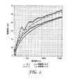
運搬用乗物の音響性能をシミュレーションするために、上記の手順に従って、実施例4、5の多層構造体の垂直入射透過損失を測定した。その結果を図2に示す。これらの実験に基づく透過損失をそれぞれ理論上の垂直入射質量則値と比較した。後者の値を式に従って計算した(例えば、R.F.Barron、「Industrial Noise Control and Acoustics,」Marcel Dekker,Inc.,New York(2003),p.112を参照のこと)。 In order to simulate the acoustic performance of the transportation vehicle, the normal incident transmission loss of the multilayer structures of Examples 4 and 5 was measured according to the above procedure. The result is shown in FIG. The transmission loss based on these experiments was compared with the theoretical normal incidence mass law value, respectively. The latter value was calculated according to the equation (see, eg, RF Barron, “Industrial Noise Control and Acoustics,” Marcel Dekker, Inc., New York (2003), p. 112).

上式で、TLnは垂直入射透過損失(dB)、log10は基底10の対数、πは約3.14の数学定数、Msは単位面積(kg/m2)当たりの多層構造体質量、ρ1及びc1は、多層構造体を囲む空気中の、それぞれ密度(kg/m3)及び音波の速度(m/s)、fは周波数(Hz)である。得られたTLnの計算値も図2に示す。運搬用乗物の音響性能をシミュレーションするために、異なる温度条件で、すなわち、室温(約23℃)、及び低温(約−79℃)か、又は高温(約+100℃)のいずれかで、上記の手順に従って、実施例4、5の多層構造体の透過損失特性も試験した。低温試験の場合、2つのドライアイスプレート(固体二酸化炭素)間で構造体を冷却した。プレート間の温度を熱電対でチェックした(≒−79℃)。高温試験の場合、構造体をオーブン(Thermolyne Sybron Corporation,Dubuque,Iowa,USAから入手可能なThermolyne(商標)Type 1300 Furnace,Model # F−B1315M,Series 140)内で+150℃に加熱した。透過損失測定を行った直後の加熱した構造体の温度は約+100℃であった(赤外線(IR)サーモメータによる)。総計試験時間(ドライアイスプレート又はオーブンから構造体を取り出し、B&K Impedance Tube内に構造体を配置し、測定を行った時間)は約50秒であった。結果を図3及び図4に示す。
Where TL n is normal incident transmission loss (dB), log 10 is the logarithm of the
本明細書で引用した特許、特許文献、及び公報に含有される参照された記述内容は、その全体が、それぞれ個別に組み込まれているかのように、参照として組み込まれる。本発明に対する様々な予見できない修正及び変更が、本発明の範囲及び趣旨から逸脱することなく当業者に明らかとなるであろう。本発明は、本明細書に記載した例示的な実施形態及び実施例によって過度に限定されるものではなく、またかかる実施例及び実施形態は、一例として表されているだけであり、ただし、本発明の範囲は、以下のように本明細書に記載した「請求項」によってのみ限定されることを意図するものと理解されるべきである。 Referenced descriptions contained in patents, patent documents, and publications cited herein are incorporated by reference as if each were incorporated individually. Various unforeseen modifications and changes to the invention will be apparent to those skilled in the art without departing from the scope and spirit of the invention. The present invention is not unduly limited by the exemplary embodiments and examples described herein, and such examples and embodiments are merely represented by way of example, although It is to be understood that the scope of the invention is intended to be limited only by the "claims" set forth herein as follows.
Claims (4)
前記音波バリアは、フォノニック結晶を有し、
該フォノニック結晶は、第1の密度を有する第1の媒質と、前記第1の密度とは異なる第2の密度を有する第2の媒質とを交互に重ねてなる層を含む多層構造体の形態の、複数の構造体からなる一次元で実質周期的なアレイを少なくとも1つ含み、
前記第1の媒質及び前記第2の媒質のうちの一方は、縦波音波の伝播速度と、横波音波の伝播速度とを有する粘弾性媒質であり、前記縦波音波の伝播速度は、前記横波音波の伝播速度の少なくとも30倍であり、
前記第1の媒質及び前記第2の媒質のうちの他方は、粘弾性媒質又は弾性媒質である、少なくとも1つの遮音装置を用意することと、
(b)運搬用乗物の音響源領域と音響受信領域との間に前記遮音装置を介在させることと、を含む、方法。 (A) providing at least one sound insulation device including at least one acoustic wave barrier,
The acoustic wave barrier has a phononic crystal,
The phononic crystals, first medium and said first density form of a multilayer structure containing a layer formed by alternately stacking a second medium having a second different density and having a first density At least one one-dimensional, substantially periodic array of a plurality of structures,
One of the first medium and the second medium is a viscoelastic medium having a propagation speed of a longitudinal wave sound wave and a propagation speed of a transverse wave sound wave, and the propagation speed of the longitudinal wave sound wave is the transverse wave. At least 30 times the propagation speed of sound waves,
Providing at least one sound insulation device, wherein the other of the first medium and the second medium is a viscoelastic medium or an elastic medium;
(B) interposing the sound insulation device between an acoustic source region and an acoustic receiving region of the transport vehicle.
前記第1の媒質及び前記第2の媒質のうちの前記他方は、弾性媒質であり、
前記複数の構造体からなる実質周期的なアレイは、前記第1の媒質と前記第2の媒質とを交互に重ねてなる層を含む多層構造体の形態の一次元アレイであり、及び/又は、
前記音波バリアは、800Hz〜1500Hzの範囲にわたって20dB以上の透過損失をもたらし、前記音波バリアは、20cm以下の厚さを有する、請求項1に記載の方法。 The viscoelastic medium is selected from viscoelastic solids, viscoelastic liquids and combinations thereof;
The other of the first medium and the second medium is an elastic medium,
The substantially periodic array of the plurality of structures is a one-dimensional array in the form of a multi-layer structure including layers in which the first medium and the second medium are alternately stacked, and / or ,
The method of claim 1, wherein the sonic barrier provides a transmission loss of 20 dB or greater over a range of 800 Hz to 1500 Hz, and the sonic barrier has a thickness of 20 cm or less.
前記フォノニック結晶は、第1の密度を有する第1の媒質中と、第2の密度を有する第2の媒質とを交互に重ねてなる層を含む多層構造体の形態の、複数の構造体からなる一次元で実質周期的なアレイを少なくとも1つ含み、
前記第1の媒質及び前記第2の媒質のうちの一方は、縦波音波の伝播速度と、横波音波の伝播速度とを有する粘弾性媒質であり、前記縦波音波の伝播速度は、前記横波音波の伝播速度の少なくとも約30倍であり、
前記第1の媒質及び前記第2の媒質のうちの他方は、粘弾性又は弾性媒質である、少なくとも1つの音波バリアと、
(b)少なくとも1つの高耐熱性材料と、を備える、遮音装置。 (A) at least one acoustic wave barrier having a phononic crystal,
The phononic crystals, and during the first medium having a first density, in the form of a multilayer structure containing a layer formed by alternately stacking a second medium having a second density, a plurality of structures Comprising at least one one-dimensional, substantially periodic array,
One of the first medium and the second medium is a viscoelastic medium having a propagation speed of a longitudinal wave sound wave and a propagation speed of a transverse wave sound wave, and the propagation speed of the longitudinal wave sound wave is the transverse wave. At least about 30 times the propagation speed of sound waves,
The other of the first medium and the second medium is at least one acoustic wave barrier that is a viscoelastic or elastic medium;
(B) A sound insulation device comprising at least one high heat resistant material.
Applications Claiming Priority (3)
| Application Number | Priority Date | Filing Date | Title |
|---|---|---|---|
| US14041308P | 2008-12-23 | 2008-12-23 | |
| US61/140,413 | 2008-12-23 | ||
| PCT/US2009/068237 WO2010075130A2 (en) | 2008-12-23 | 2009-12-16 | Transportation vehicle sound insulation process and device |
Publications (3)
| Publication Number | Publication Date |
|---|---|
| JP2012513622A JP2012513622A (en) | 2012-06-14 |
| JP2012513622A5 JP2012513622A5 (en) | 2013-01-10 |
| JP5819731B2 true JP5819731B2 (en) | 2015-11-24 |
Family
ID=42288384
Family Applications (1)
| Application Number | Title | Priority Date | Filing Date |
|---|---|---|---|
| JP2011543577A Expired - Fee Related JP5819731B2 (en) | 2008-12-23 | 2009-12-16 | Sound insulation method and apparatus for transportation vehicles |
Country Status (6)
| Country | Link |
|---|---|
| US (1) | US8276709B2 (en) |
| EP (1) | EP2376311B1 (en) |
| JP (1) | JP5819731B2 (en) |
| KR (1) | KR101723250B1 (en) |
| CN (1) | CN102317118B (en) |
| WO (1) | WO2010075130A2 (en) |
Families Citing this family (8)
| Publication number | Priority date | Publication date | Assignee | Title |
|---|---|---|---|---|
| US9324312B2 (en) * | 2007-12-21 | 2016-04-26 | 3M Innovative Properties Company | Viscoelastic phononic crystal |
| EP2376038A2 (en) * | 2008-12-23 | 2011-10-19 | 3M Innovative Properties Company | Hearing protection process and device |
| KR101821825B1 (en) * | 2009-06-25 | 2018-01-24 | 쓰리엠 이노베이티브 프로퍼티즈 컴파니 | Sound barrier for audible acoustic frequency management |
| WO2014074372A1 (en) * | 2012-11-08 | 2014-05-15 | 3M Innovative Properties Company | Uv-curable silicone release compositions |
| US8875838B1 (en) * | 2013-04-25 | 2014-11-04 | Toyota Motor Engineering & Manufacturing North America, Inc. | Acoustic and elastic flatband formation in phononic crystals:methods and devices formed therefrom |
| KR101427855B1 (en) * | 2013-09-11 | 2014-08-07 | 한국과학기술원 | Sound insulation system |
| DE102016222889B4 (en) * | 2016-11-21 | 2018-10-25 | Schaeffler Technologies AG & Co. KG | Roll stabilizer for a motor vehicle and method for producing a roll stabilizer |
| CN109050175A (en) * | 2018-07-06 | 2018-12-21 | 北京航空航天大学 | Based on the structure for inhibiting the resonance of doughnut internal cavity that phonon crystal noise reduction is theoretical |
Family Cites Families (26)
| Publication number | Priority date | Publication date | Assignee | Title |
|---|---|---|---|---|
| JPS61237729A (en) * | 1985-04-11 | 1986-10-23 | 清水建設株式会社 | Laminated sound shielding panel |
| US5188123A (en) | 1990-08-20 | 1993-02-23 | Cabot Safety Corporation | Hearing protective earplug having alternative modes of insertion |
| US5203352A (en) | 1990-10-16 | 1993-04-20 | Cabot Safety Corporation | Polymeric foam earplug |
| EP0521740A1 (en) * | 1991-04-25 | 1993-01-07 | Hutchinson | Material for acoustic protection and device incorporating such material |
| FR2696407B1 (en) * | 1992-10-05 | 1994-12-02 | Peugeot | Acoustic insulation device, in particular for a front apron of a motor vehicle. |
| US5298694A (en) * | 1993-01-21 | 1994-03-29 | Minnesota Mining And Manufacturing Company | Acoustical insulating web |
| JP2640078B2 (en) * | 1993-02-08 | 1997-08-13 | 株式会社神戸製鋼所 | Damping profiles and structures for transport aircraft |
| US5792998A (en) | 1993-04-19 | 1998-08-11 | Cabot Safety Intermediate Corporation | Acoustical hearing protective devices utilizing dynamically stiff foam and methods of producing same |
| JP3158801B2 (en) * | 1993-08-31 | 2001-04-23 | 日産自動車株式会社 | Sound insulation structure |
| JP3284729B2 (en) * | 1994-02-09 | 2002-05-20 | 日産自動車株式会社 | Automotive sound insulating material and method of manufacturing the same |
| FR2727189B1 (en) * | 1994-11-21 | 1997-01-24 | Peripherie | ACOUSTIC INSULATING PANEL AND METHOD OF MANUFACTURING |
| DE29520198U1 (en) * | 1995-12-20 | 1996-02-08 | Roever Hermann | Soundproofing component made of sheet metal |
| DE19821532A1 (en) * | 1998-05-14 | 1999-11-25 | Hp Chemie Pelzer Res & Dev | Lower cost, heat and noise absorbing shroud, manufacturing method and use of shroud in an engine vehicle compartment |
| KR100426127B1 (en) * | 2001-07-19 | 2004-04-08 | 네이버시스템(주) | Transmission system for moving pictures |
| US6705268B2 (en) | 2001-09-21 | 2004-03-16 | Basf Aktiengesellschaft | Engine noise barrier |
| EP1682385B1 (en) | 2003-10-31 | 2008-10-15 | Dow Global Technologies Inc. | Sound insulating system |
| AU2005209264A1 (en) | 2004-01-23 | 2005-08-11 | Cabot Safety Intermediate Corporation | High attenuating earmuff device |
| JP2005246952A (en) * | 2004-02-04 | 2005-09-15 | Nihon Glassfiber Industrial Co Ltd | Sound and heat insulating material for vehicle and its surface layer material |
| SE528345C2 (en) | 2004-06-16 | 2006-10-24 | Howard Leight Ind Llc | Cover intended to be used as a hearing protector, ways of producing the same and use of such a cover |
| JP2006106211A (en) | 2004-10-01 | 2006-04-20 | Toyota Motor Corp | High-rigidity dash silencer |
| JP2006257993A (en) | 2005-03-17 | 2006-09-28 | Tokai Rubber Ind Ltd | Soundproof cover |
| JP2007015292A (en) | 2005-07-08 | 2007-01-25 | Sekisui Chem Co Ltd | Damping material |
| US7708110B2 (en) | 2007-04-30 | 2010-05-04 | Kimberly-Clark Worldwide, Inc. | Bandless hearing protector and method |
| US7770692B2 (en) * | 2007-09-14 | 2010-08-10 | Gm Global Technology Operations, Inc. | Engine acoustic treatment |
| US8132643B2 (en) * | 2007-12-21 | 2012-03-13 | 3M Innovative Properties Company | Sound barrier for audible acoustic frequency management |
| KR101821825B1 (en) * | 2009-06-25 | 2018-01-24 | 쓰리엠 이노베이티브 프로퍼티즈 컴파니 | Sound barrier for audible acoustic frequency management |
-
2009
- 2009-12-16 CN CN200980156906.XA patent/CN102317118B/en not_active Expired - Fee Related
- 2009-12-16 US US13/140,577 patent/US8276709B2/en active Active
- 2009-12-16 WO PCT/US2009/068237 patent/WO2010075130A2/en active Application Filing
- 2009-12-16 EP EP09835616.5A patent/EP2376311B1/en not_active Not-in-force
- 2009-12-16 KR KR1020117017269A patent/KR101723250B1/en active IP Right Grant
- 2009-12-16 JP JP2011543577A patent/JP5819731B2/en not_active Expired - Fee Related
Also Published As
| Publication number | Publication date |
|---|---|
| EP2376311B1 (en) | 2016-05-18 |
| CN102317118B (en) | 2014-03-12 |
| EP2376311A4 (en) | 2012-05-23 |
| KR101723250B1 (en) | 2017-04-04 |
| US8276709B2 (en) | 2012-10-02 |
| WO2010075130A2 (en) | 2010-07-01 |
| US20110247893A1 (en) | 2011-10-13 |
| JP2012513622A (en) | 2012-06-14 |
| CN102317118A (en) | 2012-01-11 |
| WO2010075130A3 (en) | 2011-01-20 |
| EP2376311A2 (en) | 2011-10-19 |
| KR20110106410A (en) | 2011-09-28 |
Similar Documents
| Publication | Publication Date | Title |
|---|---|---|
| JP5819731B2 (en) | Sound insulation method and apparatus for transportation vehicles | |
| US8132643B2 (en) | Sound barrier for audible acoustic frequency management | |
| KR101821825B1 (en) | Sound barrier for audible acoustic frequency management | |
| US20110000741A1 (en) | Process for Audible Acoustic Frequency Management in Gas Flow Systems | |
| US7263028B2 (en) | Composite acoustic attenuation materials | |
| US10923094B2 (en) | Soundproof structure | |
| JP2007509816A (en) | Sound insulation system | |
| AU658054B2 (en) | Membranous-vibration sound absorbing materials | |
| TWI596011B (en) | Acoustic material | |
| JP2007320289A (en) | Honeycomb sandwich panel having soundproof characteristic | |
| Zent et al. | Automotive sound absorbing material survey results | |
| JP2012513288A (en) | Hearing protection method and apparatus | |
| Jain et al. | Evaluation of acoustic performance of automotive seats by experimental and simulation techniques | |
| Egab et al. | Prediction of interior trim sound absorption using Statistical Energy Analysis | |
| Jain et al. | Sound Package Materials for Vehicle Interior NVH Refinement | |
| Liu et al. | Experimental and numerical investigation of enclosed cavity noise in the presence of interior trim materials | |
| Liu et al. | Acoustic characterization of vehicle interior trims | |
| Rajaram | Experimental study of acoustical behavior of flat honeycomb sandwich panel | |
| Scope et al. | Lyle F. Yerges | |
| KR20160055430A (en) | Sound insulation board structure |
Legal Events
| Date | Code | Title | Description |
|---|---|---|---|
| A521 | Written amendment |
Free format text: JAPANESE INTERMEDIATE CODE: A523 Effective date: 20121114 |
|
| A621 | Written request for application examination |
Free format text: JAPANESE INTERMEDIATE CODE: A621 Effective date: 20121114 |
|
| A977 | Report on retrieval |
Free format text: JAPANESE INTERMEDIATE CODE: A971007 Effective date: 20130521 |
|
| A131 | Notification of reasons for refusal |
Free format text: JAPANESE INTERMEDIATE CODE: A131 Effective date: 20130528 |
|
| A601 | Written request for extension of time |
Free format text: JAPANESE INTERMEDIATE CODE: A601 Effective date: 20130827 |
|
| A602 | Written permission of extension of time |
Free format text: JAPANESE INTERMEDIATE CODE: A602 Effective date: 20130903 |
|
| A521 | Written amendment |
Free format text: JAPANESE INTERMEDIATE CODE: A523 Effective date: 20131128 |
|
| A131 | Notification of reasons for refusal |
Free format text: JAPANESE INTERMEDIATE CODE: A131 Effective date: 20140805 |
|
| A601 | Written request for extension of time |
Free format text: JAPANESE INTERMEDIATE CODE: A601 Effective date: 20141104 |
|
| A602 | Written permission of extension of time |
Free format text: JAPANESE INTERMEDIATE CODE: A602 Effective date: 20141111 |
|
| A521 | Written amendment |
Free format text: JAPANESE INTERMEDIATE CODE: A523 Effective date: 20150205 |
|
| TRDD | Decision of grant or rejection written | ||
| A01 | Written decision to grant a patent or to grant a registration (utility model) |
Free format text: JAPANESE INTERMEDIATE CODE: A01 Effective date: 20150901 |
|
| A61 | First payment of annual fees (during grant procedure) |
Free format text: JAPANESE INTERMEDIATE CODE: A61 Effective date: 20151001 |
|
| R150 | Certificate of patent or registration of utility model |
Ref document number: 5819731 Country of ref document: JP Free format text: JAPANESE INTERMEDIATE CODE: R150 |
|
| R250 | Receipt of annual fees |
Free format text: JAPANESE INTERMEDIATE CODE: R250 |
|
| LAPS | Cancellation because of no payment of annual fees |