EP2500457B1 - Flame retardant mat plate material for construction, and preparation method thereof - Google Patents
Flame retardant mat plate material for construction, and preparation method thereof Download PDFInfo
- Publication number
- EP2500457B1 EP2500457B1 EP10830071.6A EP10830071A EP2500457B1 EP 2500457 B1 EP2500457 B1 EP 2500457B1 EP 10830071 A EP10830071 A EP 10830071A EP 2500457 B1 EP2500457 B1 EP 2500457B1
- Authority
- EP
- European Patent Office
- Prior art keywords
- metallic
- hardening
- mat
- flame retardant
- agent
- Prior art date
- Legal status (The legal status is an assumption and is not a legal conclusion. Google has not performed a legal analysis and makes no representation as to the accuracy of the status listed.)
- Not-in-force
Links
Images


Classifications
-
- B—PERFORMING OPERATIONS; TRANSPORTING
- B23—MACHINE TOOLS; METAL-WORKING NOT OTHERWISE PROVIDED FOR
- B23K—SOLDERING OR UNSOLDERING; WELDING; CLADDING OR PLATING BY SOLDERING OR WELDING; CUTTING BY APPLYING HEAT LOCALLY, e.g. FLAME CUTTING; WORKING BY LASER BEAM
- B23K11/00—Resistance welding; Severing by resistance heating
- B23K11/24—Electric supply or control circuits therefor
- B23K11/241—Electric supplies
- B23K11/243—Multiple welding installations fed by one source
-
- D—TEXTILES; PAPER
- D04—BRAIDING; LACE-MAKING; KNITTING; TRIMMINGS; NON-WOVEN FABRICS
- D04H—MAKING TEXTILE FABRICS, e.g. FROM FIBRES OR FILAMENTARY MATERIAL; FABRICS MADE BY SUCH PROCESSES OR APPARATUS, e.g. FELTS, NON-WOVEN FABRICS; COTTON-WOOL; WADDING ; NON-WOVEN FABRICS FROM STAPLE FIBRES, FILAMENTS OR YARNS, BONDED WITH AT LEAST ONE WEB-LIKE MATERIAL DURING THEIR CONSOLIDATION
- D04H1/00—Non-woven fabrics formed wholly or mainly of staple fibres or like relatively short fibres
- D04H1/40—Non-woven fabrics formed wholly or mainly of staple fibres or like relatively short fibres from fleeces or layers composed of fibres without existing or potential cohesive properties
- D04H1/42—Non-woven fabrics formed wholly or mainly of staple fibres or like relatively short fibres from fleeces or layers composed of fibres without existing or potential cohesive properties characterised by the use of certain kinds of fibres insofar as this use has no preponderant influence on the consolidation of the fleece
- D04H1/4209—Inorganic fibres
- D04H1/4234—Metal fibres
-
- D—TEXTILES; PAPER
- D04—BRAIDING; LACE-MAKING; KNITTING; TRIMMINGS; NON-WOVEN FABRICS
- D04H—MAKING TEXTILE FABRICS, e.g. FROM FIBRES OR FILAMENTARY MATERIAL; FABRICS MADE BY SUCH PROCESSES OR APPARATUS, e.g. FELTS, NON-WOVEN FABRICS; COTTON-WOOL; WADDING ; NON-WOVEN FABRICS FROM STAPLE FIBRES, FILAMENTS OR YARNS, BONDED WITH AT LEAST ONE WEB-LIKE MATERIAL DURING THEIR CONSOLIDATION
- D04H1/00—Non-woven fabrics formed wholly or mainly of staple fibres or like relatively short fibres
- D04H1/40—Non-woven fabrics formed wholly or mainly of staple fibres or like relatively short fibres from fleeces or layers composed of fibres without existing or potential cohesive properties
- D04H1/58—Non-woven fabrics formed wholly or mainly of staple fibres or like relatively short fibres from fleeces or layers composed of fibres without existing or potential cohesive properties by applying, incorporating or activating chemical or thermoplastic bonding agents, e.g. adhesives
- D04H1/587—Non-woven fabrics formed wholly or mainly of staple fibres or like relatively short fibres from fleeces or layers composed of fibres without existing or potential cohesive properties by applying, incorporating or activating chemical or thermoplastic bonding agents, e.g. adhesives characterised by the bonding agents used
-
- D—TEXTILES; PAPER
- D04—BRAIDING; LACE-MAKING; KNITTING; TRIMMINGS; NON-WOVEN FABRICS
- D04H—MAKING TEXTILE FABRICS, e.g. FROM FIBRES OR FILAMENTARY MATERIAL; FABRICS MADE BY SUCH PROCESSES OR APPARATUS, e.g. FELTS, NON-WOVEN FABRICS; COTTON-WOOL; WADDING ; NON-WOVEN FABRICS FROM STAPLE FIBRES, FILAMENTS OR YARNS, BONDED WITH AT LEAST ONE WEB-LIKE MATERIAL DURING THEIR CONSOLIDATION
- D04H1/00—Non-woven fabrics formed wholly or mainly of staple fibres or like relatively short fibres
- D04H1/40—Non-woven fabrics formed wholly or mainly of staple fibres or like relatively short fibres from fleeces or layers composed of fibres without existing or potential cohesive properties
- D04H1/58—Non-woven fabrics formed wholly or mainly of staple fibres or like relatively short fibres from fleeces or layers composed of fibres without existing or potential cohesive properties by applying, incorporating or activating chemical or thermoplastic bonding agents, e.g. adhesives
- D04H1/64—Non-woven fabrics formed wholly or mainly of staple fibres or like relatively short fibres from fleeces or layers composed of fibres without existing or potential cohesive properties by applying, incorporating or activating chemical or thermoplastic bonding agents, e.g. adhesives the bonding agent being applied in wet state, e.g. chemical agents in dispersions or solutions
- D04H1/645—Impregnation followed by a solidification process
-
- E—FIXED CONSTRUCTIONS
- E04—BUILDING
- E04B—GENERAL BUILDING CONSTRUCTIONS; WALLS, e.g. PARTITIONS; ROOFS; FLOORS; CEILINGS; INSULATION OR OTHER PROTECTION OF BUILDINGS
- E04B1/00—Constructions in general; Structures which are not restricted either to walls, e.g. partitions, or floors or ceilings or roofs
- E04B1/62—Insulation or other protection; Elements or use of specified material therefor
- E04B1/92—Protection against other undesired influences or dangers
- E04B1/94—Protection against other undesired influences or dangers against fire
- E04B1/941—Building elements specially adapted therefor
- E04B1/942—Building elements specially adapted therefor slab-shaped
-
- Y—GENERAL TAGGING OF NEW TECHNOLOGICAL DEVELOPMENTS; GENERAL TAGGING OF CROSS-SECTIONAL TECHNOLOGIES SPANNING OVER SEVERAL SECTIONS OF THE IPC; TECHNICAL SUBJECTS COVERED BY FORMER USPC CROSS-REFERENCE ART COLLECTIONS [XRACs] AND DIGESTS
- Y10—TECHNICAL SUBJECTS COVERED BY FORMER USPC
- Y10T—TECHNICAL SUBJECTS COVERED BY FORMER US CLASSIFICATION
- Y10T29/00—Metal working
- Y10T29/14—Shredding metal or metal wool article making
-
- Y—GENERAL TAGGING OF NEW TECHNOLOGICAL DEVELOPMENTS; GENERAL TAGGING OF CROSS-SECTIONAL TECHNOLOGIES SPANNING OVER SEVERAL SECTIONS OF THE IPC; TECHNICAL SUBJECTS COVERED BY FORMER USPC CROSS-REFERENCE ART COLLECTIONS [XRACs] AND DIGESTS
- Y10—TECHNICAL SUBJECTS COVERED BY FORMER USPC
- Y10T—TECHNICAL SUBJECTS COVERED BY FORMER US CLASSIFICATION
- Y10T428/00—Stock material or miscellaneous articles
- Y10T428/12—All metal or with adjacent metals
- Y10T428/12347—Plural layers discontinuously bonded [e.g., spot-weld, mechanical fastener, etc.]
-
- Y—GENERAL TAGGING OF NEW TECHNOLOGICAL DEVELOPMENTS; GENERAL TAGGING OF CROSS-SECTIONAL TECHNOLOGIES SPANNING OVER SEVERAL SECTIONS OF THE IPC; TECHNICAL SUBJECTS COVERED BY FORMER USPC CROSS-REFERENCE ART COLLECTIONS [XRACs] AND DIGESTS
- Y10—TECHNICAL SUBJECTS COVERED BY FORMER USPC
- Y10T—TECHNICAL SUBJECTS COVERED BY FORMER US CLASSIFICATION
- Y10T428/00—Stock material or miscellaneous articles
- Y10T428/12—All metal or with adjacent metals
- Y10T428/12424—Mass of only fibers
-
- Y—GENERAL TAGGING OF NEW TECHNOLOGICAL DEVELOPMENTS; GENERAL TAGGING OF CROSS-SECTIONAL TECHNOLOGIES SPANNING OVER SEVERAL SECTIONS OF THE IPC; TECHNICAL SUBJECTS COVERED BY FORMER USPC CROSS-REFERENCE ART COLLECTIONS [XRACs] AND DIGESTS
- Y10—TECHNICAL SUBJECTS COVERED BY FORMER USPC
- Y10T—TECHNICAL SUBJECTS COVERED BY FORMER US CLASSIFICATION
- Y10T442/00—Fabric [woven, knitted, or nonwoven textile or cloth, etc.]
- Y10T442/20—Coated or impregnated woven, knit, or nonwoven fabric which is not [a] associated with another preformed layer or fiber layer or, [b] with respect to woven and knit, characterized, respectively, by a particular or differential weave or knit, wherein the coating or impregnation is neither a foamed material nor a free metal or alloy layer
-
- Y—GENERAL TAGGING OF NEW TECHNOLOGICAL DEVELOPMENTS; GENERAL TAGGING OF CROSS-SECTIONAL TECHNOLOGIES SPANNING OVER SEVERAL SECTIONS OF THE IPC; TECHNICAL SUBJECTS COVERED BY FORMER USPC CROSS-REFERENCE ART COLLECTIONS [XRACs] AND DIGESTS
- Y10—TECHNICAL SUBJECTS COVERED BY FORMER USPC
- Y10T—TECHNICAL SUBJECTS COVERED BY FORMER US CLASSIFICATION
- Y10T442/00—Fabric [woven, knitted, or nonwoven textile or cloth, etc.]
- Y10T442/30—Woven fabric [i.e., woven strand or strip material]
- Y10T442/3382—Including a free metal or alloy constituent
- Y10T442/339—Metal or metal-coated strand
-
- Y—GENERAL TAGGING OF NEW TECHNOLOGICAL DEVELOPMENTS; GENERAL TAGGING OF CROSS-SECTIONAL TECHNOLOGIES SPANNING OVER SEVERAL SECTIONS OF THE IPC; TECHNICAL SUBJECTS COVERED BY FORMER USPC CROSS-REFERENCE ART COLLECTIONS [XRACs] AND DIGESTS
- Y10—TECHNICAL SUBJECTS COVERED BY FORMER USPC
- Y10T—TECHNICAL SUBJECTS COVERED BY FORMER US CLASSIFICATION
- Y10T442/00—Fabric [woven, knitted, or nonwoven textile or cloth, etc.]
- Y10T442/60—Nonwoven fabric [i.e., nonwoven strand or fiber material]
- Y10T442/654—Including a free metal or alloy constituent
- Y10T442/655—Metal or metal-coated strand or fiber material
Definitions
- the present invention relates to a flame retardant mat plate material for construction, and a preparation method thereof, and in particular to a mat plate which is characterized in that in a flame retardant mat plate for construction, a mat shaped plate is manufactured in such a way that a metallic thread made from an iron, a nonferrous metal, a waste can and a waste tin plate, etc. is tangled like a cotton wool in a thin sheet shape, so it is possible to recycle materials, and an inflammability can be enhanced, and a heat insulation effect can be maximized, and a recycling rate can be enhanced in terms of a material management, and the production of wastes can be advantageously minimized, thus contributing a lot to a green industry growth throughout the world.
- a flame retardant mat plate for construction is generally made from asbestos, glass cotton, etc.
- the asbestos is manufactured from ore, the production cost of which is low, and heat insulation and soundproof performance are excellent. So, the asbestos had been widely used since 1960s to 1970s.
- the asbestos is generally classified as a top class cancer-causing substance which is produced in the course of demolishment of buildings, so the application of the asbestos is very restricted.
- a glass cotton has been used for asbestos, which glass cotton is known as having excellent heat insulation and soundproof effects.
- glass cotton is very limited because it is generally used as a heat insulation material or a soundproof material to be attached to a wall. Since a glass cotton per se does not have a support force enough to stably support a certain frame structure, and it cannot be also applied as a floor material.
- a flame retardant mat plate material for construction and a preparation method thereof in which a mat shaped plate is manufactured in such a way that a mat shaped plate is manufactured as a metallic thread made from an iron, a nonferrous metal, a waste can and a waste tin plate, etc. is tangled like a cotton wool in a thin sheet shape.
- the present invention is characterized in that a flame retardant mat plate for construction according to the present invention is made from a metallic thread from an iron, a nonferrous metal, a waste can, a waste tin plate, etc., so materials can be recycled, and inflammability, soundproof and heat insulation performances are maximized, and a recycling rate in the course of demolishment of buildings can be enhanced, and wastes are produced least, which all contribute to a green growth of the world.
- the present invention is basically directed to enhancing an inflammability and recycling performance in case of a flame retardant mat plate for construction.
- the flame retardant mat plate for construction according to the present invention is characterized in that a metallic mat 10 is formed in such a way that a metallic thread made in a thin shape from an iron, a nonferrous metal, a waste can or a waste thin plate is tangled like a cotton wool or the like.
- the metallic thread has 1 ⁇ 0.1 mm thickness which might help enhance a lightness and a heat insulation performance. It is preferred that an anticorrosion agent such as a zinc and urea resin, an epoxy resin, a cement or a gypsum is coated on an outer surface, thus preventing corrosion.
- an anticorrosion agent such as a zinc and urea resin, an epoxy resin, a cement or a gypsum is coated on an outer surface, thus preventing corrosion.
- the coating of the anticorrosion agent is conducted on an outer surface of a metallic thread in the course of the manufacture of a metallic thread or a zinc and urea resin, an epoxy resin, a cement and a gypsum, and an anticorrosion agent is coated in a plating, a spray or an immersion fluid way following the manufacture of a metallic mat 10 with a metallic thread, so the metallic thread forming a metallic mat 10 is coagulated each other for thereby obtaining a durable construction.
- a protection sheet 11 is attached at both sides of a metallic mat 10, thus preventing the inputs of foreign substances into the interior of a metallic cotton wool.
- the protection sheet 11 is made from one among a metallic, thin sheet, an inflammable paper sheet and an inflammable woven cloth.
- a hardening finishing agent is coated on at least one surface of the metallic mat 10, with the hardening finishing agent being made in such a way that a metallic thread is cut a certain length and impregnated and mixed with one hardening finishing paste selected among a hardening resin such as an urea resin and an epoxy resin and a hardening gypsum agent such as a cement and a gypsum, thus enhancing a durable hardening finishing layer 12.
- a hardening resin such as an urea resin and an epoxy resin
- a hardening gypsum agent such as a cement and a gypsum
- the metallic mat 10 might be formed in a double layer structure or preferably more structures with the aid of engaging members at least at two portions.
- the engaging member might be a plated engaging part 21 in which a metallic thread is interconnected by means of a plating material in a plating method.
- the metallic mat is submerged in water in the plating bathtub 31, and the (-) electrode 33 is made to come into contact with the engaging portion, and the (+) electrode 32 engaged with the plating metal 34 is made to come close to the opposite side of the (-) electrode 33, thus forming a plating engaging part 21 at the engaging part through a concentrated plating.
- a plating hole 21 a is formed at the plating engaging part 21 of the metallic mat 10, passing through the same.
- the plating engaging part 21 is formed at an inner wall of the plating hole 21 a.
- a spot welding engaging part 22 can be formed so that the facing metallic threads are combined by a stop welding method.
- a welding power supplier 42 for supplying a high voltage power for the spot welding
- a rotary distributor 43 for sequentially distributing the electric power so as to prevent overload of the welding electric power supplier 42 owing to the concurrent power supply to the plurality of the welding ports 41, so welding works are sequentially performed.
- a rivet engaging part 23 might be implemented, in which engagement is performed with the aid of rivets. It is preferred that the rivets of the rivet engaging part 23 are eye rivets with each of its center being passed though.
- a hardening adhesive engaging part 24 might be formed of one hardening adhesive agent selected among a hardening resin adhesive agent such as an urea resin and an epoxy resin and a hardening gypsum adhesive agent such as a cement and a gypsum.
- a hardening resin adhesive agent such as an urea resin and an epoxy resin
- a hardening gypsum adhesive agent such as a cement and a gypsum
- the hardening adhesive engaging part 24, as shown in Figure 12 might be implemented by partially inserting a hardening adhesive agent into the metallic mat 10 or as shown in Figure 13 , a circular diameter hardening adhesive agent 25 made from a circular diameter hardening adhesive agent is impregnated during the manufacture of the metallic mat 10 and is pressed by a press machine, and the metallic thread of the metallic mat 10 to which the impregnated circular diameter hardening adhesive agent 25 is engaged is tangled with the circular diameter hardening adhesive agent 25.
- the engaging member it might be tangled with a single metallic thread hardening adhesive agent 26 manufactured in such a manner that a metallic thread is cut and impregnated and mixed with one hardening adhesive paste selected among a hardening resin agent such as an urea resin and an epoxy resin and a hardening gypsum agent such as a cement and a gypsum.
- a hardening resin agent such as an urea resin and an epoxy resin
- a hardening gypsum agent such as a cement and a gypsum
- the metallic mat might be manufactured in such a way to combine and impregnate together a metallic thread and a hardening adhesive agent.
- the engagement can be down through the entire portions with resin.
- the adhesive agent can be injected with the aid of pressure from the lower side of the metallic mat 10 or alternatively, the metallic mat 10 can be inputted into a container filled with a hardening adhesive agent.
- a metallic thread made in a thin shape from a metallic material such as an iron, a nonferrous metal or the like is tangled like a cotton wool, thus manufacturing a metallic mat 10.
- the flame retardant mat plate for construction according to the present invention can be well applied to an interior material like a partition wall or the like or can be engaged into the interior of an exterior material like a soundproof wall, thus efficiently maintaining a soundproof function, a heat insulation function and an inflammable function.
- the present invention uses a metallic wire, so an applicable range of material is very wide, and in case of a demolishment of buildings, a lot of wastes can be recycled without leaving any wastes behind.
- the flame retardant mat plate for construction according to the present invention is made from a metallic material, it cannot be easily cut, and an intruder cannot easily break the flame retardant mat plate for construction for trespassing.
- the flame retardant mat plate for construction according to the present invention when a bigger porous is adapted without using a protection sheet, can be used as a core material enhancing a strength of a concrete cast material of a building.
- the flame retardant mat plate for construction can be used as a finishing material at a partition wall when a hardening finishing layer 12 is formed at a metallic mat 10.
- the flame retardant mat plate for construction according to the present invention is made from a metallic thread, a recycling is promoted, and an inflammability, soundproof performance and heat insulation effect can be maximized.
Landscapes
- Engineering & Computer Science (AREA)
- Textile Engineering (AREA)
- Chemical & Material Sciences (AREA)
- Architecture (AREA)
- Chemical Kinetics & Catalysis (AREA)
- Civil Engineering (AREA)
- Structural Engineering (AREA)
- Electromagnetism (AREA)
- Physics & Mathematics (AREA)
- Dispersion Chemistry (AREA)
- General Chemical & Material Sciences (AREA)
- Mechanical Engineering (AREA)
- Inorganic Chemistry (AREA)
- Building Environments (AREA)
- Laminated Bodies (AREA)
- Floor Finish (AREA)
- Finishing Walls (AREA)
Description
- The present invention relates to a flame retardant mat plate material for construction, and a preparation method thereof, and in particular to a mat plate which is characterized in that in a flame retardant mat plate for construction, a mat shaped plate is manufactured in such a way that a metallic thread made from an iron, a nonferrous metal, a waste can and a waste tin plate, etc. is tangled like a cotton wool in a thin sheet shape, so it is possible to recycle materials, and an inflammability can be enhanced, and a heat insulation effect can be maximized, and a recycling rate can be enhanced in terms of a material management, and the production of wastes can be advantageously minimized, thus contributing a lot to a green industry growth throughout the world.
- A flame retardant mat plate for construction is generally made from asbestos, glass cotton, etc.
- The asbestos is manufactured from ore, the production cost of which is low, and heat insulation and soundproof performance are excellent. So, the asbestos had been widely used since 1960s to 1970s.
- The asbestos is generally classified as a top class cancer-causing substance which is produced in the course of demolishment of buildings, so the application of the asbestos is very restricted.
- Alternatively, a glass cotton has been used for asbestos, which glass cotton is known as having excellent heat insulation and soundproof effects.
- The above-described glass cotton costs a lot in terms of its manufacture, and recycling is impossible. In the course of its application, a worker's finger might be easily hurt with a piece of glass, which results in a lot of problems when in use.
- The recycle of glass cotton is almost impossible, and a lot of wastes are produced in the course of demolishment of buildings.
- The applicable scope of glass cotton is very limited because it is generally used as a heat insulation material or a soundproof material to be attached to a wall. Since a glass cotton per se does not have a support force enough to stably support a certain frame structure, and it cannot be also applied as a floor material.
- Accordingly, it is an object of the present invention to provide a flame retardant mat plate material for construction, and a preparation method thereof which can overcome the problems in a conventional art in which the price of a flame retardant mat plate for construction is high, and recycle is impossible, and a lot of construction wastes are produced, and its handling is risky.
- To achieve the above objects, there is provided a flame retardant mat plate material for construction, and a preparation method thereof in which a mat shaped plate is manufactured in such a way that a mat shaped plate is manufactured as a metallic thread made from an iron, a nonferrous metal, a waste can and a waste tin plate, etc. is tangled like a cotton wool in a thin sheet shape.
- Therefore, the present invention is characterized in that a flame retardant mat plate for construction according to the present invention is made from a metallic thread from an iron, a nonferrous metal, a waste can, a waste tin plate, etc., so materials can be recycled, and inflammability, soundproof and heat insulation performances are maximized, and a recycling rate in the course of demolishment of buildings can be enhanced, and wastes are produced least, which all contribute to a green growth of the world.
- The present invention will become better understood with reference to the accompanying drawings which are given only by way of illustration and thus are not limitative of the present invention, wherein;
-
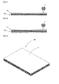
Figure 1 is a perspective view illustrating an embodiment of the present invention; -
Figure 2 is a perspective view illustrating a protection sheet according to an embodiment of the present invention; -
Figures 3 and 4 are side views illustrating a side view illustrating a hardening finishing layer according to an embodiment of the present invention; -
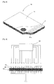
Figure 5 is a perspective view illustrating an example that a metal mat is formed in a double layer structure according to an embodiment of the present invention; -
Figures 6, 7 and8 are views illustrating an example that a metallic mat is formed in a double layer structure with the aid of a plating engaging part according to an embodiment of the present invention; -
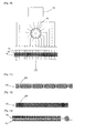
Figures 9 and10 are views illustrating an example that a metallic mat is formed in a double layer structure with the aid of a spot welding engaging part according to an embodiment of the present invention; -
Figure 11 is a view illustrating an example that a metallic mat is formed in a double layer structure with the aid of a rivet engaging part according to an embodiment of the present invention; -
Figure 12 is a view illustrating an example that a metallic mat is formed in a double layer structure with the aid of a hardening adhesive engaging part according to an embodiment of the present invention; -
Figure 13 is a view illustrating an example of a single metallic thread-combined hardening adhesive engaging part according to an embodiment of the present invention; -
Figure 14 is a view illustrating an example that a metallic mat is formed in a double layer structure with the aid of a hardening adhesive engaging part, and a hardening adhesive agent is formed of a circular diameter hardening adhesive agent according to an embodiment of the present invention; and -
Figure 15 is a side cross sectional view illustrating a state that a resin is impregnated into the whole portions of a metallic mat according to an embodiment of the present invention. -
- 1: metallic thread
- 10: metallic mat
- 11: protection sheet
- 12: hardening finishing layer
- 21: plating engaging part
- 21a: plating hole
- 22: stop welding engaging part
- 23: rivet engaging part
- 24: single metallic thread-combined hardening adhesive engaging part
- 25: circular diameter hardening adhesive agent
- 31: plating bathtub
- 32: positive electrode
- 33: negative electrode
- 34: plating metal
- 41: welding port
- 42: welding power supplier
- 43: rotary distributor
- The preferred embodiment of the present invention will be described with reference to the accompanying drawings.
- The present invention is basically directed to enhancing an inflammability and recycling performance in case of a flame retardant mat plate for construction.
- The flame retardant mat plate for construction according to the present invention is characterized in that a
metallic mat 10 is formed in such a way that a metallic thread made in a thin shape from an iron, a nonferrous metal, a waste can or a waste thin plate is tangled like a cotton wool or the like. - It is preferred that the metallic thread has 1~0.1 mm thickness which might help enhance a lightness and a heat insulation performance. It is preferred that an anticorrosion agent such as a zinc and urea resin, an epoxy resin, a cement or a gypsum is coated on an outer surface, thus preventing corrosion.
- The coating of the anticorrosion agent is conducted on an outer surface of a metallic thread in the course of the manufacture of a metallic thread or a zinc and urea resin, an epoxy resin, a cement and a gypsum, and an anticorrosion agent is coated in a plating, a spray or an immersion fluid way following the manufacture of a
metallic mat 10 with a metallic thread, so the metallic thread forming ametallic mat 10 is coagulated each other for thereby obtaining a durable construction. - In the embodiment of the present invention, as shown in
Figure 2 , it is appreciated that aprotection sheet 11 is attached at both sides of ametallic mat 10, thus preventing the inputs of foreign substances into the interior of a metallic cotton wool. - It is preferred that the
protection sheet 11 is made from one among a metallic, thin sheet, an inflammable paper sheet and an inflammable woven cloth. - In the embodiment of the present invention, as shown in
Figures 3 an 4, a hardening finishing agent is coated on at least one surface of themetallic mat 10, with the hardening finishing agent being made in such a way that a metallic thread is cut a certain length and impregnated and mixed with one hardening finishing paste selected among a hardening resin such as an urea resin and an epoxy resin and a hardening gypsum agent such as a cement and a gypsum, thus enhancing a durablehardening finishing layer 12. - It is appreciated that the
metallic mat 10 might be formed in a double layer structure or preferably more structures with the aid of engaging members at least at two portions. - As shown in
Figures 6 to 8 , the engaging member might be a platedengaging part 21 in which a metallic thread is interconnected by means of a plating material in a plating method. The metallic mat is submerged in water in theplating bathtub 31, and the (-)electrode 33 is made to come into contact with the engaging portion, and the (+)electrode 32 engaged with theplating metal 34 is made to come close to the opposite side of the (-)electrode 33, thus forming aplating engaging part 21 at the engaging part through a concentrated plating. - For a reliable, concentrated engaging work by means of the
plating engaging part 21, as shown inFigures 7 and8 , aplating hole 21 a is formed at theplating engaging part 21 of themetallic mat 10, passing through the same. Theplating engaging part 21 is formed at an inner wall of theplating hole 21 a. - According to another example of the engaging member, as shown in
Figures 9 and10 , a spotwelding engaging part 22 can be formed so that the facing metallic threads are combined by a stop welding method. As shown inFigure 10 , there are provided a plurality ofwelding ports 41, awelding power supplier 42 for supplying a high voltage power for the spot welding, and arotary distributor 43 for sequentially distributing the electric power so as to prevent overload of the weldingelectric power supplier 42 owing to the concurrent power supply to the plurality of thewelding ports 41, so welding works are sequentially performed. - According to another example of the engaging member, as shown in
Figure 11 , arivet engaging part 23 might be implemented, in which engagement is performed with the aid of rivets. It is preferred that the rivets of therivet engaging part 23 are eye rivets with each of its center being passed though. - According to another example of the engaging member, as shown in
Figures 12 and 13 , a hardeningadhesive engaging part 24 might be formed of one hardening adhesive agent selected among a hardening resin adhesive agent such as an urea resin and an epoxy resin and a hardening gypsum adhesive agent such as a cement and a gypsum. - The hardening
adhesive engaging part 24, as shown inFigure 12 , might be implemented by partially inserting a hardening adhesive agent into themetallic mat 10 or as shown inFigure 13 , a circular diameter hardeningadhesive agent 25 made from a circular diameter hardening adhesive agent is impregnated during the manufacture of themetallic mat 10 and is pressed by a press machine, and the metallic thread of themetallic mat 10 to which the impregnated circular diameter hardeningadhesive agent 25 is engaged is tangled with the circular diameter hardeningadhesive agent 25. - According to another example of the engaging member, it might be tangled with a single metallic thread hardening
adhesive agent 26 manufactured in such a manner that a metallic thread is cut and impregnated and mixed with one hardening adhesive paste selected among a hardening resin agent such as an urea resin and an epoxy resin and a hardening gypsum agent such as a cement and a gypsum. - As shown in
Figure 15 , the metallic mat might be manufactured in such a way to combine and impregnate together a metallic thread and a hardening adhesive agent. In a double layer structure, the engagement can be down through the entire portions with resin. The adhesive agent can be injected with the aid of pressure from the lower side of themetallic mat 10 or alternatively, themetallic mat 10 can be inputted into a container filled with a hardening adhesive agent. - The operations of the present invention will be described.
- As described above, in terms of the flame retardant mat plate for construction according to the present invention, a metallic thread made in a thin shape from a metallic material such as an iron, a nonferrous metal or the like is tangled like a cotton wool, thus manufacturing a
metallic mat 10. The flame retardant mat plate for construction according to the present invention can be well applied to an interior material like a partition wall or the like or can be engaged into the interior of an exterior material like a soundproof wall, thus efficiently maintaining a soundproof function, a heat insulation function and an inflammable function. - The present invention uses a metallic wire, so an applicable range of material is very wide, and in case of a demolishment of buildings, a lot of wastes can be recycled without leaving any wastes behind.
- Since the flame retardant mat plate for construction according to the present invention is made from a metallic material, it cannot be easily cut, and an intruder cannot easily break the flame retardant mat plate for construction for trespassing.
- In the present invention, when a bigger porous is adapted without using a protection sheet, the flame retardant mat plate for construction according to the present invention can be used as a core material enhancing a strength of a concrete cast material of a building.
- In the preferred embodiment of the present invention, the flame retardant mat plate for construction can be used as a finishing material at a partition wall when a hardening
finishing layer 12 is formed at ametallic mat 10. - Accordingly, the flame retardant mat plate for construction according to the present invention is made from a metallic thread, a recycling is promoted, and an inflammability, soundproof performance and heat insulation effect can be maximized.
- In addition, it is appreciated that a recycling rate of materials produced in the course of a demolition of a building can be enhanced, and the producing amount of wastes can be minimized, which consequently contributes to a green industry growth throughout the world.
Claims (6)
- A method for manufacturing a flame retardant mat plate material suitable to be used for construction, comprising:a step of forming a metallic mat (10) in such a way that a metallic thread having a thickness of 1~0.1 mm is tangled with each other like a cotton wool,wherein said metallic mat (10) is formed in a double layer structure,the method further comprising:engaging the double layer structure with the aid of an engaging means provided at at least two portions, said engaging means being selected from either:(i) a spot welding engaging part (22) formed in such a way that facing metallic threads are engaged by means of spot welding; or(ii) a rivet engaging part (23) in which engagement is performed by means of rivets.
- A method for manufacturing a flame retardant mat plate material according to claim 1, wherein, in engagement means (i), spot welding is performed using a plurality of welding ports (41) and a welding electric power supplier (42) which serves to supply a high electric power for spot welding.
- A method for manufacturing a flame retardant mat plate material according to claim 2, wherein a rotary distributor (43) is provided for sequentially distributing an electric power to the plurality of the welding ports (41).
- A method for manufacturing a flame retardant mat plate material for construction according to any preceding claim, wherein the metallic mat is made in such a way to mix together the metallic thread with a hardening adhesive agent of either a hardening resin or a hardening gypsum agent.
- A method for manufacturing a flame retardant mat plate material according to claim 4, wherein the hardening resin agent is selected from one of a urea resin and an epoxy resin or the hardening gypsum agent is selected from one of a cement and a gypsum.
- A method for manufacturing a flame retardant mat plate material according to any preceding claim, the method further comprising:attaching a protection sheet (11) to both sides of a metallic mat (10) in such a way to prevent the invasion of foreign substances, wherein the protection sheet (11) is made from one of: a metallic, thin sheet; an inflammable paper sheet; and an inflammable woven sheet; andcoating a hardening finishing agent on at least one surface of the metallic mat 10 to form a hardening finishing layer (12), wherein said hardening finishing agent is made by cutting a metallic thread to a certain length, and impregnating and mixing the metallic thread with a hardening finishing agent paste of either a hardening resin agent or a hardening gypsum agent.
Applications Claiming Priority (2)
| Application Number | Priority Date | Filing Date | Title |
|---|---|---|---|
| KR20090107809 | 2009-11-10 | ||
| PCT/KR2010/000225 WO2011059138A1 (en) | 2009-11-10 | 2010-01-14 | Flame retardant mat plate material for construction, and preparation method thereof |
Publications (3)
| Publication Number | Publication Date |
|---|---|
| EP2500457A1 EP2500457A1 (en) | 2012-09-19 |
| EP2500457A4 EP2500457A4 (en) | 2013-04-24 |
| EP2500457B1 true EP2500457B1 (en) | 2014-11-26 |
Family
ID=43933151
Family Applications (1)
| Application Number | Title | Priority Date | Filing Date |
|---|---|---|---|
| EP10830071.6A Not-in-force EP2500457B1 (en) | 2009-11-10 | 2010-01-14 | Flame retardant mat plate material for construction, and preparation method thereof |
Country Status (6)
| Country | Link |
|---|---|
| US (1) | US20120251837A1 (en) |
| EP (1) | EP2500457B1 (en) |
| KR (1) | KR101034694B1 (en) |
| CN (1) | CN102510912A (en) |
| RU (1) | RU2523268C2 (en) |
| WO (1) | WO2011059138A1 (en) |
Families Citing this family (3)
| Publication number | Priority date | Publication date | Assignee | Title |
|---|---|---|---|---|
| KR101122681B1 (en) | 2011-10-06 | 2012-03-09 | 김동수 | Enlatged footbridge and bicycle road established in slope and breast wall, and constructing method of the same |
| NL1040411C2 (en) * | 2013-09-26 | 2015-03-30 | Pul Isoleermaterialenind Bv | METHOD FOR MANUFACTURING A LAMINARY CONSTRUCTION PLATE |
| CN110078439A (en) * | 2019-04-19 | 2019-08-02 | 卓匈新材料科技(上海)有限公司 | The artificial stone of sesame ash artificial stone slurry and its curing molding |
Family Cites Families (22)
| Publication number | Priority date | Publication date | Assignee | Title |
|---|---|---|---|---|
| US1490544A (en) * | 1922-02-01 | 1924-04-15 | American Steel Wool Mfg Compan | Preparation of steel wool |
| US2463565A (en) * | 1942-12-09 | 1949-03-08 | Ruben Samuel | Dry primary cell |
| SU82170A1 (en) * | 1948-11-30 | 1949-11-30 | Д.Н. Евсеев | Method of making metallic construction materials by pressing |
| US3469297A (en) * | 1966-04-20 | 1969-09-30 | Brunswick Corp | Porous metal structure |
| US3390750A (en) * | 1966-10-25 | 1968-07-02 | Borg Warner | Friction element having a layer of porous sintered metal fibers |
| US4410678A (en) * | 1981-12-28 | 1983-10-18 | Ford Motor Company | Coating composition comprising chain-extendable crosslinkable polyol and diblocked diisocyanate diurea oligomer |
| JPS60103104A (en) * | 1983-11-10 | 1985-06-07 | Nippon Seisen Kk | Web consisting of short metallic fiber and its production |
| JPS6331750A (en) * | 1986-07-28 | 1988-02-10 | 株式会社 材料科学研究所 | Immersion lining method of iron steel product |
| SU1551488A1 (en) * | 1988-03-09 | 1990-03-23 | Институт Электросварки Им.Е.О.Патона | Apparatus for controlling arc spot or seam welding |
| DE4021628A1 (en) * | 1990-07-06 | 1992-01-16 | Kiha Textilien Gmbh | FIBER STRUCTURE AND MOLDING OBTAINED FROM IT, AND METHOD FOR THE PRODUCTION THEREOF |
| RU2037037C1 (en) * | 1992-03-30 | 1995-06-09 | Центральный Научно-Исследовательский И Проектно-Экспериментальный Институт Комплексных Проблем Строительных Конструкций И Сооружений Им.В.А.Кучеренко | Light-weight fencing panel |
| JPH06313250A (en) * | 1993-04-27 | 1994-11-08 | Wakamatsu Netsuren Kk | Copper-based metallic nonwoven fabric and its production |
| RU2063304C1 (en) * | 1994-06-10 | 1996-07-10 | Физико-технический институт им.А.Ф.Иоффе РАН | Process of briquetting of metal chips |
| JP3383468B2 (en) * | 1995-05-17 | 2003-03-04 | 積水樹脂株式会社 | Porous sound absorbing plate |
| RU2165982C1 (en) * | 1999-08-04 | 2001-04-27 | Открытое акционерное общество "Западно-Сибирский металлургический комбинат" | Method of charging of blast furnace |
| AUPR001800A0 (en) * | 2000-09-08 | 2000-10-05 | Structural Monitoring Systems Ltd | Method and apparatus for monitoring the integrity of structures |
| US6465110B1 (en) * | 2000-10-10 | 2002-10-15 | Material Sciences Corporation | Metal felt laminate structures |
| US6964828B2 (en) * | 2001-04-27 | 2005-11-15 | 3M Innovative Properties Company | Cathode compositions for lithium-ion batteries |
| KR20030095484A (en) * | 2002-06-10 | 2003-12-24 | 화인알루테크 주식회사 | Sound absorbing plate using aluminium and method thereof |
| KR100700212B1 (en) * | 2004-12-14 | 2007-03-27 | 전남대학교산학협력단 | Assembly of coil springs and sandwich panel using the same |
| WO2007018051A1 (en) * | 2005-08-09 | 2007-02-15 | Nichimen Chemical Industry Co., Ltd. | Process for production of laminated materials |
| KR200415142Y1 (en) * | 2006-02-17 | 2006-04-27 | 장재식 | Construction composite board |
-
2010
- 2010-01-14 CN CN2010800369158A patent/CN102510912A/en active Pending
- 2010-01-14 WO PCT/KR2010/000225 patent/WO2011059138A1/en active Application Filing
- 2010-01-14 EP EP10830071.6A patent/EP2500457B1/en not_active Not-in-force
- 2010-01-14 RU RU2012102053/03A patent/RU2523268C2/en not_active IP Right Cessation
- 2010-01-14 US US13/384,141 patent/US20120251837A1/en not_active Abandoned
- 2010-09-14 KR KR1020100089794A patent/KR101034694B1/en not_active IP Right Cessation
Also Published As
| Publication number | Publication date |
|---|---|
| CN102510912A (en) | 2012-06-20 |
| KR101034694B1 (en) | 2011-05-16 |
| RU2523268C2 (en) | 2014-07-20 |
| US20120251837A1 (en) | 2012-10-04 |
| KR20110025729A (en) | 2011-03-11 |
| EP2500457A1 (en) | 2012-09-19 |
| WO2011059138A1 (en) | 2011-05-19 |
| RU2012102053A (en) | 2013-12-20 |
| EP2500457A4 (en) | 2013-04-24 |
Similar Documents
| Publication | Publication Date | Title |
|---|---|---|
| EP2500457B1 (en) | Flame retardant mat plate material for construction, and preparation method thereof | |
| US20170368792A1 (en) | Backing layer of a thermal insulation panel for building having increased adhesion properties to an insulating layer | |
| EP3110624A1 (en) | Fiber-reinforced coated mats and mat-faced panels and methods | |
| KR100925530B1 (en) | Steel and fiber composite panel for concrete structure reinforcement and the concrete structure means of reinforcement work for which this production technique and this were used | |
| CN203640076U (en) | Fire-proof structure sprayed with mortar for steel beam or steel column | |
| CN103835469A (en) | Keel-free stone material dry-sticking structure | |
| US20120247047A1 (en) | Welded Wire Lath | |
| KR200172590Y1 (en) | Laminated wall panel for container house | |
| CN103321330A (en) | Wire mesh grid-type molded polystyrene board | |
| CN101769020B (en) | Thermal insulation aseismic wall | |
| CN212176286U (en) | Composite environment-friendly insulation board with improved structure | |
| CN207363301U (en) | A kind of carbon fiber composite material reinforced chemical factory floor | |
| CN204401923U (en) | Acoustical cotton coating structure | |
| CN207892066U (en) | A kind of assembled fire prevention integrated building component | |
| KR20100133871A (en) | A board for build and its manufacturing method | |
| CN205476209U (en) | Light -duty heat preservation decorative board | |
| KR100647471B1 (en) | Method for producing hybrid stud and the hybrid stud manufactured by using the same | |
| CN210759581U (en) | Fireproof composite aluminum product convenient to splice | |
| CN212200763U (en) | Novel steel construction for building | |
| CN213014968U (en) | Prefabricated external wall panel of assembly type structure | |
| CN214834076U (en) | Hot-dip galvanized steel bar with buckle connection structure | |
| CN214833532U (en) | Corrosion-resistant building steel structure | |
| CN218758108U (en) | Phosphogypsum light partition board | |
| CN213952660U (en) | Long service life's truss floor board | |
| CN111877574B (en) | FS exterior sheathing cast in situ concrete composite insulation structure |
Legal Events
| Date | Code | Title | Description |
|---|---|---|---|
| PUAI | Public reference made under article 153(3) epc to a published international application that has entered the european phase |
Free format text: ORIGINAL CODE: 0009012 |
|
| 17P | Request for examination filed |
Effective date: 20120326 |
|
| AK | Designated contracting states |
Kind code of ref document: A1 Designated state(s): AT BE BG CH CY CZ DE DK EE ES FI FR GB GR HR HU IE IS IT LI LT LU LV MC MK MT NL NO PL PT RO SE SI SK SM TR |
|
| DAX | Request for extension of the european patent (deleted) | ||
| A4 | Supplementary search report drawn up and despatched |
Effective date: 20130321 |
|
| RIC1 | Information provided on ipc code assigned before grant |
Ipc: D06M 15/564 20060101ALI20130315BHEP Ipc: D04H 1/14 20060101ALI20130315BHEP Ipc: D04H 13/00 20060101AFI20130315BHEP Ipc: D06M 15/55 20060101ALI20130315BHEP |
|
| GRAP | Despatch of communication of intention to grant a patent |
Free format text: ORIGINAL CODE: EPIDOSNIGR1 |
|
| INTG | Intention to grant announced |
Effective date: 20140623 |
|
| GRAS | Grant fee paid |
Free format text: ORIGINAL CODE: EPIDOSNIGR3 |
|
| GRAA | (expected) grant |
Free format text: ORIGINAL CODE: 0009210 |
|
| AK | Designated contracting states |
Kind code of ref document: B1 Designated state(s): AT BE BG CH CY CZ DE DK EE ES FI FR GB GR HR HU IE IS IT LI LT LU LV MC MK MT NL NO PL PT RO SE SI SK SM TR |
|
| REG | Reference to a national code |
Ref country code: GB Ref legal event code: FG4D |
|
| RIN1 | Information on inventor provided before grant (corrected) |
Inventor name: NA, SUNG-MIN |
|
| REG | Reference to a national code |
Ref country code: CH Ref legal event code: EP |
|
| REG | Reference to a national code |
Ref country code: AT Ref legal event code: REF Ref document number: 698298 Country of ref document: AT Kind code of ref document: T Effective date: 20141215 |
|
| REG | Reference to a national code |
Ref country code: IE Ref legal event code: FG4D |
|
| REG | Reference to a national code |
Ref country code: DE Ref legal event code: R096 Ref document number: 602010020609 Country of ref document: DE Effective date: 20150108 |
|
| REG | Reference to a national code |
Ref country code: FR Ref legal event code: PLFP Year of fee payment: 6 |
|
| REG | Reference to a national code |
Ref country code: NL Ref legal event code: VDEP Effective date: 20141126 |
|
| REG | Reference to a national code |
Ref country code: AT Ref legal event code: MK05 Ref document number: 698298 Country of ref document: AT Kind code of ref document: T Effective date: 20141126 |
|
| REG | Reference to a national code |
Ref country code: LT Ref legal event code: MG4D |
|
| PG25 | Lapsed in a contracting state [announced via postgrant information from national office to epo] |
Ref country code: LT Free format text: LAPSE BECAUSE OF FAILURE TO SUBMIT A TRANSLATION OF THE DESCRIPTION OR TO PAY THE FEE WITHIN THE PRESCRIBED TIME-LIMIT Effective date: 20141126 Ref country code: ES Free format text: LAPSE BECAUSE OF FAILURE TO SUBMIT A TRANSLATION OF THE DESCRIPTION OR TO PAY THE FEE WITHIN THE PRESCRIBED TIME-LIMIT Effective date: 20141126 Ref country code: PT Free format text: LAPSE BECAUSE OF FAILURE TO SUBMIT A TRANSLATION OF THE DESCRIPTION OR TO PAY THE FEE WITHIN THE PRESCRIBED TIME-LIMIT Effective date: 20150326 Ref country code: NO Free format text: LAPSE BECAUSE OF FAILURE TO SUBMIT A TRANSLATION OF THE DESCRIPTION OR TO PAY THE FEE WITHIN THE PRESCRIBED TIME-LIMIT Effective date: 20150226 Ref country code: FI Free format text: LAPSE BECAUSE OF FAILURE TO SUBMIT A TRANSLATION OF THE DESCRIPTION OR TO PAY THE FEE WITHIN THE PRESCRIBED TIME-LIMIT Effective date: 20141126 Ref country code: NL Free format text: LAPSE BECAUSE OF FAILURE TO SUBMIT A TRANSLATION OF THE DESCRIPTION OR TO PAY THE FEE WITHIN THE PRESCRIBED TIME-LIMIT Effective date: 20141126 Ref country code: IS Free format text: LAPSE BECAUSE OF FAILURE TO SUBMIT A TRANSLATION OF THE DESCRIPTION OR TO PAY THE FEE WITHIN THE PRESCRIBED TIME-LIMIT Effective date: 20150326 |
|
| PGFP | Annual fee paid to national office [announced via postgrant information from national office to epo] |
Ref country code: DE Payment date: 20150130 Year of fee payment: 6 |
|
| PG25 | Lapsed in a contracting state [announced via postgrant information from national office to epo] |
Ref country code: GR Free format text: LAPSE BECAUSE OF FAILURE TO SUBMIT A TRANSLATION OF THE DESCRIPTION OR TO PAY THE FEE WITHIN THE PRESCRIBED TIME-LIMIT Effective date: 20150227 Ref country code: SE Free format text: LAPSE BECAUSE OF FAILURE TO SUBMIT A TRANSLATION OF THE DESCRIPTION OR TO PAY THE FEE WITHIN THE PRESCRIBED TIME-LIMIT Effective date: 20141126 Ref country code: CY Free format text: LAPSE BECAUSE OF FAILURE TO SUBMIT A TRANSLATION OF THE DESCRIPTION OR TO PAY THE FEE WITHIN THE PRESCRIBED TIME-LIMIT Effective date: 20141126 Ref country code: HR Free format text: LAPSE BECAUSE OF FAILURE TO SUBMIT A TRANSLATION OF THE DESCRIPTION OR TO PAY THE FEE WITHIN THE PRESCRIBED TIME-LIMIT Effective date: 20141126 Ref country code: LV Free format text: LAPSE BECAUSE OF FAILURE TO SUBMIT A TRANSLATION OF THE DESCRIPTION OR TO PAY THE FEE WITHIN THE PRESCRIBED TIME-LIMIT Effective date: 20141126 Ref country code: AT Free format text: LAPSE BECAUSE OF FAILURE TO SUBMIT A TRANSLATION OF THE DESCRIPTION OR TO PAY THE FEE WITHIN THE PRESCRIBED TIME-LIMIT Effective date: 20141126 |
|
| PGFP | Annual fee paid to national office [announced via postgrant information from national office to epo] |
Ref country code: GB Payment date: 20150218 Year of fee payment: 6 Ref country code: FR Payment date: 20150130 Year of fee payment: 6 |
|
| PG25 | Lapsed in a contracting state [announced via postgrant information from national office to epo] |
Ref country code: DK Free format text: LAPSE BECAUSE OF FAILURE TO SUBMIT A TRANSLATION OF THE DESCRIPTION OR TO PAY THE FEE WITHIN THE PRESCRIBED TIME-LIMIT Effective date: 20141126 Ref country code: RO Free format text: LAPSE BECAUSE OF FAILURE TO SUBMIT A TRANSLATION OF THE DESCRIPTION OR TO PAY THE FEE WITHIN THE PRESCRIBED TIME-LIMIT Effective date: 20141126 Ref country code: EE Free format text: LAPSE BECAUSE OF FAILURE TO SUBMIT A TRANSLATION OF THE DESCRIPTION OR TO PAY THE FEE WITHIN THE PRESCRIBED TIME-LIMIT Effective date: 20141126 Ref country code: SK Free format text: LAPSE BECAUSE OF FAILURE TO SUBMIT A TRANSLATION OF THE DESCRIPTION OR TO PAY THE FEE WITHIN THE PRESCRIBED TIME-LIMIT Effective date: 20141126 Ref country code: CZ Free format text: LAPSE BECAUSE OF FAILURE TO SUBMIT A TRANSLATION OF THE DESCRIPTION OR TO PAY THE FEE WITHIN THE PRESCRIBED TIME-LIMIT Effective date: 20141126 |
|
| REG | Reference to a national code |
Ref country code: DE Ref legal event code: R097 Ref document number: 602010020609 Country of ref document: DE |
|
| REG | Reference to a national code |
Ref country code: CH Ref legal event code: PL |
|
| PG25 | Lapsed in a contracting state [announced via postgrant information from national office to epo] |
Ref country code: PL Free format text: LAPSE BECAUSE OF FAILURE TO SUBMIT A TRANSLATION OF THE DESCRIPTION OR TO PAY THE FEE WITHIN THE PRESCRIBED TIME-LIMIT Effective date: 20141126 Ref country code: LU Free format text: LAPSE BECAUSE OF FAILURE TO SUBMIT A TRANSLATION OF THE DESCRIPTION OR TO PAY THE FEE WITHIN THE PRESCRIBED TIME-LIMIT Effective date: 20150114 |
|
| PG25 | Lapsed in a contracting state [announced via postgrant information from national office to epo] |
Ref country code: MC Free format text: LAPSE BECAUSE OF FAILURE TO SUBMIT A TRANSLATION OF THE DESCRIPTION OR TO PAY THE FEE WITHIN THE PRESCRIBED TIME-LIMIT Effective date: 20141126 |
|
| PLBE | No opposition filed within time limit |
Free format text: ORIGINAL CODE: 0009261 |
|
| STAA | Information on the status of an ep patent application or granted ep patent |
Free format text: STATUS: NO OPPOSITION FILED WITHIN TIME LIMIT |
|
| PG25 | Lapsed in a contracting state [announced via postgrant information from national office to epo] |
Ref country code: CH Free format text: LAPSE BECAUSE OF NON-PAYMENT OF DUE FEES Effective date: 20150131 Ref country code: LI Free format text: LAPSE BECAUSE OF NON-PAYMENT OF DUE FEES Effective date: 20150131 |
|
| 26N | No opposition filed |
Effective date: 20150827 |
|
| REG | Reference to a national code |
Ref country code: IE Ref legal event code: MM4A |
|
| PG25 | Lapsed in a contracting state [announced via postgrant information from national office to epo] |
Ref country code: IT Free format text: LAPSE BECAUSE OF FAILURE TO SUBMIT A TRANSLATION OF THE DESCRIPTION OR TO PAY THE FEE WITHIN THE PRESCRIBED TIME-LIMIT Effective date: 20141126 |
|
| PG25 | Lapsed in a contracting state [announced via postgrant information from national office to epo] |
Ref country code: IE Free format text: LAPSE BECAUSE OF NON-PAYMENT OF DUE FEES Effective date: 20150114 |
|
| PG25 | Lapsed in a contracting state [announced via postgrant information from national office to epo] |
Ref country code: SI Free format text: LAPSE BECAUSE OF FAILURE TO SUBMIT A TRANSLATION OF THE DESCRIPTION OR TO PAY THE FEE WITHIN THE PRESCRIBED TIME-LIMIT Effective date: 20141126 |
|
| REG | Reference to a national code |
Ref country code: DE Ref legal event code: R119 Ref document number: 602010020609 Country of ref document: DE |
|
| GBPC | Gb: european patent ceased through non-payment of renewal fee |
Effective date: 20160114 |
|
| REG | Reference to a national code |
Ref country code: FR Ref legal event code: ST Effective date: 20160930 |
|
| PG25 | Lapsed in a contracting state [announced via postgrant information from national office to epo] |
Ref country code: GB Free format text: LAPSE BECAUSE OF NON-PAYMENT OF DUE FEES Effective date: 20160114 Ref country code: DE Free format text: LAPSE BECAUSE OF NON-PAYMENT OF DUE FEES Effective date: 20160802 |
|
| PG25 | Lapsed in a contracting state [announced via postgrant information from national office to epo] |
Ref country code: FR Free format text: LAPSE BECAUSE OF NON-PAYMENT OF DUE FEES Effective date: 20160201 |
|
| PG25 | Lapsed in a contracting state [announced via postgrant information from national office to epo] |
Ref country code: MT Free format text: LAPSE BECAUSE OF FAILURE TO SUBMIT A TRANSLATION OF THE DESCRIPTION OR TO PAY THE FEE WITHIN THE PRESCRIBED TIME-LIMIT Effective date: 20141126 |
|
| PG25 | Lapsed in a contracting state [announced via postgrant information from national office to epo] |
Ref country code: BG Free format text: LAPSE BECAUSE OF FAILURE TO SUBMIT A TRANSLATION OF THE DESCRIPTION OR TO PAY THE FEE WITHIN THE PRESCRIBED TIME-LIMIT Effective date: 20141126 Ref country code: HU Free format text: LAPSE BECAUSE OF FAILURE TO SUBMIT A TRANSLATION OF THE DESCRIPTION OR TO PAY THE FEE WITHIN THE PRESCRIBED TIME-LIMIT; INVALID AB INITIO Effective date: 20100114 Ref country code: SM Free format text: LAPSE BECAUSE OF FAILURE TO SUBMIT A TRANSLATION OF THE DESCRIPTION OR TO PAY THE FEE WITHIN THE PRESCRIBED TIME-LIMIT Effective date: 20141126 |
|
| PG25 | Lapsed in a contracting state [announced via postgrant information from national office to epo] |
Ref country code: BE Free format text: LAPSE BECAUSE OF NON-PAYMENT OF DUE FEES Effective date: 20150131 |
|
| PG25 | Lapsed in a contracting state [announced via postgrant information from national office to epo] |
Ref country code: TR Free format text: LAPSE BECAUSE OF FAILURE TO SUBMIT A TRANSLATION OF THE DESCRIPTION OR TO PAY THE FEE WITHIN THE PRESCRIBED TIME-LIMIT Effective date: 20141126 |
|
| PG25 | Lapsed in a contracting state [announced via postgrant information from national office to epo] |
Ref country code: MK Free format text: LAPSE BECAUSE OF FAILURE TO SUBMIT A TRANSLATION OF THE DESCRIPTION OR TO PAY THE FEE WITHIN THE PRESCRIBED TIME-LIMIT Effective date: 20141126 |