EP1195518A2 - Vorrichtung und Verfahren zum Dosieren von Material - Google Patents
Vorrichtung und Verfahren zum Dosieren von Material Download PDFInfo
- Publication number
- EP1195518A2 EP1195518A2 EP01123104A EP01123104A EP1195518A2 EP 1195518 A2 EP1195518 A2 EP 1195518A2 EP 01123104 A EP01123104 A EP 01123104A EP 01123104 A EP01123104 A EP 01123104A EP 1195518 A2 EP1195518 A2 EP 1195518A2
- Authority
- EP
- European Patent Office
- Prior art keywords
- piston
- housing
- movable piston
- movable
- distance
- Prior art date
- Legal status (The legal status is an assumption and is not a legal conclusion. Google has not performed a legal analysis and makes no representation as to the accuracy of the status listed.)
- Withdrawn
Links
- 238000000034 method Methods 0.000 title claims abstract description 28
- 238000005086 pumping Methods 0.000 title 1
- 239000000463 material Substances 0.000 claims abstract description 72
- 239000000853 adhesive Substances 0.000 claims description 15
- 230000001070 adhesive effect Effects 0.000 claims description 15
- 230000008569 process Effects 0.000 claims description 8
- 230000001133 acceleration Effects 0.000 claims description 7
- 238000006073 displacement reaction Methods 0.000 claims 2
- 239000007788 liquid Substances 0.000 description 10
- 230000008901 benefit Effects 0.000 description 8
- 230000015572 biosynthetic process Effects 0.000 description 6
- 238000010276 construction Methods 0.000 description 3
- 230000000694 effects Effects 0.000 description 3
- 238000011156 evaluation Methods 0.000 description 3
- 230000005484 gravity Effects 0.000 description 3
- 238000004519 manufacturing process Methods 0.000 description 3
- 238000009736 wetting Methods 0.000 description 3
- 230000009471 action Effects 0.000 description 2
- 238000013461 design Methods 0.000 description 2
- 239000003292 glue Substances 0.000 description 2
- 230000003068 static effect Effects 0.000 description 2
- 239000000758 substrate Substances 0.000 description 2
- 230000007423 decrease Effects 0.000 description 1
- 230000003247 decreasing effect Effects 0.000 description 1
- 230000002996 emotional effect Effects 0.000 description 1
- 238000005516 engineering process Methods 0.000 description 1
- 239000002360 explosive Substances 0.000 description 1
- 239000004615 ingredient Substances 0.000 description 1
- 238000012986 modification Methods 0.000 description 1
- 230000004048 modification Effects 0.000 description 1
- 238000012544 monitoring process Methods 0.000 description 1
- 238000002203 pretreatment Methods 0.000 description 1
- 230000004044 response Effects 0.000 description 1
- 238000012546 transfer Methods 0.000 description 1
Images

Classifications
-
- F—MECHANICAL ENGINEERING; LIGHTING; HEATING; WEAPONS; BLASTING
- F04—POSITIVE - DISPLACEMENT MACHINES FOR LIQUIDS; PUMPS FOR LIQUIDS OR ELASTIC FLUIDS
- F04B—POSITIVE-DISPLACEMENT MACHINES FOR LIQUIDS; PUMPS
- F04B13/00—Pumps specially modified to deliver fixed or variable measured quantities
-
- F—MECHANICAL ENGINEERING; LIGHTING; HEATING; WEAPONS; BLASTING
- F04—POSITIVE - DISPLACEMENT MACHINES FOR LIQUIDS; PUMPS FOR LIQUIDS OR ELASTIC FLUIDS
- F04B—POSITIVE-DISPLACEMENT MACHINES FOR LIQUIDS; PUMPS
- F04B17/00—Pumps characterised by combination with, or adaptation to, specific driving engines or motors
- F04B17/003—Pumps characterised by combination with, or adaptation to, specific driving engines or motors driven by piezoelectric means
-
- F—MECHANICAL ENGINEERING; LIGHTING; HEATING; WEAPONS; BLASTING
- F04—POSITIVE - DISPLACEMENT MACHINES FOR LIQUIDS; PUMPS FOR LIQUIDS OR ELASTIC FLUIDS
- F04B—POSITIVE-DISPLACEMENT MACHINES FOR LIQUIDS; PUMPS
- F04B7/00—Piston machines or pumps characterised by having positively-driven valving
- F04B7/008—Piston machines or pumps characterised by having positively-driven valving the distribution being realised by moving the cylinder itself, e.g. by sliding or swinging
Definitions
- the present invention relates to a device for Dosing of material with a fixed piston, a movable one Piston and a movable housing with a lockable with one of the pistons by moving the housing Material supply and one with one of the pistons material discharge that can be closed by moving the housing, the axis of the fixed piston with the axis of the movable piston is aligned and between fixed piston and the movable piston at least then there is a distance in the area of the material feed if the material supply is open.
- the invention further relates to a method of dosing material in which (A) Material by a material supply to a filling area Housing is fed during a material export the housing of a fixed piston or a movable Piston is closed, the filling area at least is partially formed by a distance which between the fixed piston and the movable piston is present, the axis of the fixed piston with the The axis of the movable piston is aligned, (B) the housing is moved in a first direction so that the material feed from the fixed piston or the movable one Piston is closed and the material discharge opened , (C) the movable piston is fed so that the distance between the fixed piston and the movable one Pistons decreased and material from material export emerges, (D) the movable piston is returned is so that the distance between the fixed Piston and the movable piston enlarged, and (E) that Housing is moved in a second direction, which the first direction is opposite.
- the dynamic pressure of the adhesives can be adjusted via the metering speed regulate. Fast dosing leads to one high back pressure; slow dosing has a low one Pressure. It should also be emphasized that the choice of one perfect length of stay is an important requirement for repeatable dosing. This applies to both for the length of stay before as well as for the length of stay after dosing. By choosing the appropriate length of stay you give the glue the time it takes to finish Relieve back pressure, so that the repeatability is optimized.
- a difficult problem of the procedures of the State of the art is that the flow behavior the liquid due to the wetting properties of the substrate to which the liquid is applied should be very different. By different Wetting properties can cause major inaccuracies result.
- the surface tension in terms of different involved materials is one of the biggest problems with regard to the exact Dosage.
- an appropriate one Pretreatment to be taken are very time consuming and expensive.
- the Surface tension affects slow drop formation the most on the needle. From a slow one Drop formation results in poor material removal. at the surface tension affects the formation of drops very quickly hardly or not at all between the dispensing needle and the adhesive not from. You shoot the drop according to the inkjet printer principle out of the needle.
- the dynamic pressure in the dispensing needle influences to a great extent the repeatability of the point order. This in particular for the reason that it's discretionary which values set the dwell times during dosing become. Depending on the setting, the desired volume can be reached a residual ingredient is added, or the volume becomes only delivered incomplete. Also with regard to the Back pressure offers rapid drop formation advantages, because the dynamic pressure can be reduced many times over. You have to keep the process time low so that the Reduce the dynamic pressure in a flash via the metering needle bore got to.
- the needle distance to the component is also very important, to counteract the surface tension.
- the setting correct needle spacing is extremely complex, especially due to the required precision of the mechanical components. This problem too can be circumvented using the inkjet printer principle, that is, by shooting the adhesive at the component becomes. Because of this, the needle distance to the component adjustable to a certain extent. This is a crucial advantage for series production, especially with a view to saving costs, since there is no need for a Z-stroke query.
- the invention builds on the prior art according to the Preamble of claim 1 characterized in that the movable Piston can be controlled by a piezo actuator.
- a piezo actuator makes it possible to use a piston pump to provide which the material according to the inkjet printer principle from a reservoir shoots out.
- Piezo actuators can be highly accurate with very little Strokes work so that extremely small volumes are dosed.
- Piezo actuators are also able to To feed pistons an enormous acceleration, so that the material is unaffected by the problems described of the prior art emerge from a metering needle can. In particular, the problems are considered on the surface tension, the dynamic pressure and the setting of the needle distance to the component is eliminated.
- the fixed piston is preferably in a precision bushing held, the movable piston is from the precision bush out, and the precision bush is in the Housing arranged.
- the precision in terms of arrangement and the guidance of the pistons is an important requirement for setting exact volumes and for good reproducibility of the dosing processes.
- the amount of material to be dosed of that in the case of open material supply Distance between the fixed piston and the movable one Piston depends in the area of the material feed.
- the piezo actuator by an adjusting screw can be positioned. In this way the system can be adjusted, the one exact setting of the respective components relative to each other.
- the adjusting screw for setting the in the case of open material supply existing distance between the fixed piston and the movable piston and the adjusting screw for positioning of the piezo actuator are identical. So you have one Adjustment screw with two functions, what with regard a simple construction of the piston pump is useful.
- the piezo actuator is preferably of the order of magnitude for a stroke of 100 ⁇ m. With such strokes extremely small volumes can be precisely dosed.
- the piezo actuator for a Acceleration in the order of 100000 g suitable is.
- the movable piston and thus the material to be dosed also has a high acceleration fed so that the material is unaffected from the surface tension and the dynamic pressure the metering opening is shot out.
- the material export has a dispensing needle.
- the device preferably has a control. On in this way a dosing process can be automated and execute with a high number of cycles.
- the method according to the invention is based on the prior art Technology according to the preamble of claim 12 thereby that the movable piston is controlled by a piezo actuator becomes.
- the inventive Advantages of the device are implemented procedurally.
- the distance between the fixed piston and the movable piston for determining the dosing Volume set. You got through this way a simple setting measure the preselection of the to be dosed Volume in hand.
- the method is particularly advantageous when using this Adhesive is dosed. Especially when it comes to glue are extreme precise dosages desired. It also switches Process the problem with regard to compressibility and the dynamic pressure of the adhesive; this in particular due to the high speed of ejection of the material.
- the piezo actuator is preferably provided with a stroke in the Order of magnitude of 100 ⁇ m. Strokes of this size allow highly precise dosing of small amounts of material.
- the piezo actuator is preferred with an acceleration in on the order of 100,000 g.
- This acceleration is an explosive discharge of the adhesive possible, so the disadvantages in terms of Surface tension and back pressure can be avoided.
- the housing is preferably provided by a pneumatic cylinder emotional. This is a highly precise and quick positioning of the housing during the course of the procedure possible.
- the method is preferably controlled by a controller.
- the process is automatic Manufacturing process can be used at high speed.
- the invention is based on the surprising finding that the use of a piezo actuator in a piston pump eliminates numerous problems which are evident in the metering of very small quantities of material. Due to the rapid formation of drops, the surface tension between the metering opening and the material to be dispensed has little or no effect. The back pressure in the dispensing needle is reduced many times over. The dispensing needle distance to the component is variable. If you compare the piezoelectric actuator with conventional actuator concepts, you will get an evaluation according to the following table (symbols: +: good, high; 0: medium; -: bad, low). The piezoelectric concept wins in particular with regard to the actuating time and also with regard to the consistently good evaluation with the various evaluation parameters. Steep link concept resolution Travel Range force Operating time Power density Temp range piezoelectric + - + + + + + + + + + 0 electromagnetic - + - - - + Pneumatic - + - - - + hydraulic - + + - + -
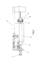
- FIG. 1 is a piston pump for dosing material shown partially cut.
- the device contains a fixed piston 10 and a movable piston 12.
- the fixed piston 10 and the movable piston 12 are axially aligned so that they are aligned.
- the device further includes a movable housing 14. Inside the housing is a precision socket 16, of which of the fixed pistons 10 is held and in which the movable piston 12 is guided.
- the housing 14 and the precision bushing 16 have lateral holes, from one as material supply 18 and the other for material export 20 serves.
- Inside the precision bush 16 a filling chamber 22 is formed by the ends of the fixed piston 10 and the movable piston 12 one Have distance from each other, which due to the Mobility of the movable piston 12 is changeable.
- the fixed piston 10 ends approximately in the middle between the material feed 18 and the Material removal 20, which can be seen from a vertical line is.
- the movable piston 12 ends in the present Representation at the position at which the dash-dot line ends.
- This dash-dot line defines one Middle position of the movable housing 14.
- Double arrow above the housing 14 indicates that the housing 14 moves through a pneumatic cylinder 24 leaves.
- the precision bush 16 is through seals 26 sealed to the outside.
- the housing 14 is through Screws 28 held together.
- the housing 14 is in the illustrated state in a position in which the material feed 18 is open and opens into the free space 22.
- the material removal 20 is however, closed by the fixed piston 10. In this Condition can thus material get into the filling chamber 22.
- the amount of material to be dosed can be checked the size of the filling chamber 22 and thus by the distance between the fixed piston 10 and the movable piston Set 12. If the filling chamber 22 is filled, it will Housing 14. Moved to the left by the pneumatic cylinder 24.
- the material feed 18 is by the movable piston 12 closed during the material removal 20 is opened.
- the housing 14 moves under Action of the pneumatic cylinder 24 again in the illustrated Home position, and the movable piston 12th also goes back to its starting position shown.
- the execution is for the inclusion of a further dose of material prepared.
- FIG. 2 details the construction of a part a piston pump with a piezo actuator 30.
- This construction includes a main plate 32 on which the other components directly or indirectly are attached.
- the piezo actuator 30 is via a holder 34 and disks 36, 38 fixed with respect to the main plate 32.
- the piezo actuator 30 is held by a holder 40 held, which is screwed directly to the main plate 32 is.
- To adjust the piezo actuator 30 is one Adjustment screw 42 is provided, which in the holder 34th sitting.
- the adjusting screw 42 can also be the distance between the movable piston 12 and that in FIG. 2 Adjust the fixed piston, not shown, whereby the volume to be dosed can be selected.
Landscapes
- Engineering & Computer Science (AREA)
- Mechanical Engineering (AREA)
- General Engineering & Computer Science (AREA)
- Coating Apparatus (AREA)
- Processing And Handling Of Plastics And Other Materials For Molding In General (AREA)
Abstract
Description
| Steilgliedkonzept | Auflösung | Stellweg | Stellkraft | Stellzeit | Leistungs dichte | Temp.-bereich |
| Piezoelektrisch | + | - | + | + | + | 0 |
| Elektromagnetisch | - | + | - | - | - | + |
| Pneumatisch | - | + | - | - | - | + |
| Hydraulisch | - | + | + | - | + | - |
| Vorteile | Nachteile |
| große mechanische Stellkräfte (bis zu einigen kN) | hohe Steuerspannungen notwendig |
| hohe Eigenfrequenz (bis zu einigen 10 kHz) | kleine Stellwege (max. 100 ...200 µm) |
| Wegauflösung im Nanometerbereich | Kennlinienhysterese und Kriecheffekte |
| sehr kurze Reaktionszeit (einige µs) | Sättigungserscheinungen |
| hohe mechanische Steifigkeit | Depolarisationsgefahr |
| unterschiedliche Wirkrichtungen | |
| spiel- und verschleißfrei |
- Figur 1
- eine teilweise geschnittene Darstellung einer Kolbenpumpe;
- Figur 2
- eine teilweise geschnittene Darstellung einer Kolbenpumpe mit Piezoaktor.
Claims (20)
- Vorrichtung zum Dosieren von Material mitdadurch gekennzeichnet, dass der bewegliche Kolben (12) von einem Piezoaktor (30) ansteuerbar ist.einem festen Kolben (10),einem beweglichen Kolben (12) undeinem beweglichen Gehäuse (14) miteiner mit einem der Kolben (10, 12) durch Bewegen des Gehäuses (14) verschließbaren Materialzufuhr (18) undeiner mit einem der Kolben (10, 12) durch Bewegen des Gehäuses (14) verschließbaren Materialausfuhr (20),wobei die Achse des festen Kolbens (10) mit der Achse des beweglichen Kolbens (12) fluchtet undwobei zwischen dem festen Kolben (10) und dem beweglichen Kolben (12) zumindest dann ein Abstand im Bereich der Materialzufuhr (18) vorliegt, wenn die Materialzufuhr offen ist,
- Vorrichtung nach Anspruch 1,
dadurch gekennzeichnet,dass der feste Kolben (10) in einer Präzisionsbuchse (16) gehalten ist,dass der bewegliche Kolben (12) von der Präzisionsbuchse (16) geführt ist unddass die Präzisionsbuchse (16) in dem Gehäuse (14) angeordnet ist. - Vorrichtung nach Anspruch 1 oder 2, dadurch gekennzeichnet, dass die Menge des zu dosierenden Materials von dem im Falle der offenen Materialzufuhr (18) vorliegenden Abstand zwischen dem festen Kolben (10) und dem beweglichen Kolben (12) im Bereich der Materialzufuhr (18) abhängt.
- Vorrichtung nach einem der vorangehenden Ansprüche, dadurch gekennzeichnet, dass der im Falle der offenen Materialzufuhr (18) vorliegende Abstand zwischen dem festen Kolben (10) und dem beweglichen Kolben (12) durch eine Einstellschraube (42) einstellbar ist.
- Vorrichtung nach einem der vorangehenden Ansprüche, dadurch gekennzeichnet, dass der Piezoaktor (30) durch eine Einstellschraube (42) positionierbar ist.
- Vorrichtung nach einem der vorangehenden Ansprüche, dadurch gekennzeichnet, dass die Einstellschraube (42) zum Einstellen des im Falle der offenen Materialzufuhr (18) vorliegenden Abstandes zwischen dem festen Kolben (10) und dem beweglichen Kolben (12) und die Einstellschraube (42) zum Positionieren des Piezoaktors (30) identisch sind.
- Vorrichtung nach einem der vorangehenden Ansprüche, dadurch gekennzeichnet, dass der Piezoaktor (30) für einen Hub in der Größenordnung von 100 µm geeignet ist.
- Vorrichtung nach einem der vorangehenden Ansprüche, dadurch gekennzeichnet, dass der Piezoaktor (30) für eine Beschleunigung in der Größenordnung von 100000 g geeignet ist.
- Vorrichtung nach einem der vorangehenden Ansprüche, dadurch gekennzeichnet, dass ein Pneumatikzylinder (24) zum Bewegen des beweglichen Gehäuses (14) vorgesehen ist.
- Vorrichtung nach einem der vorangehenden Ansprüche, dadurch gekennzeichnet, dass die Materialausfuhr (20) eine Dosiernadel aufweist.
- Vorrichtung nach einem der vorangehenden Ansprüche, dadurch gekennzeichnet, dass die Vorrichtung eine Steuerung aufweist.
- Verfahren zum Dosieren von Material, bei demdadurch gekennzeichnet, dass der bewegliche Kolben (12) von einem Piezoaktor (30) angesteuert wird.Material durch eine Materialzufuhr (18) einem Füllbereich (22) eines Gehäuses (14) zugeführt wird, während eine Materialausfuhr (20) des Gehäuses von einem festen Kolben (10) oder einem beweglichen Kolben (12) verschlossen ist,wobei der Füllbereich (22) zumindest teilweise durch einen Abstand gebildet ist, welcher zwischen dem festen Kolben (10) und dem beweglichen Kolben (12) vorliegt, undwobei die Achse des festen Kolbens (10) mit der Achse des beweglichen Kolbens (12) fluchtet,das Gehäuse in eine erste Richtung verschoben wird, sc dass die Materialzufuhr (18) von dem festen Kolben (10) oder dem beweglichen Kolben (12) verschlossen wird und die Materialabfuhr (20) geöffnet wird,der bewegliche Kolben (12) zugestellt wird, so dass sich der Abstand zwischen dem festen Kolben (10) und dem beweglichen Kolben (12) verringert und Material aus der Materialausfuhr (20) austritt,der bewegliche Kolben (12) zurückgeführt wird, so dass sich der Abstand zwischen dem festen Kolben (10) und dem beweglichen Kolben (12) vergrößert, unddas Gehäuse (14) in eine zweite Richtung verschoben wird, die der ersten Richtung entgegengesetzt ist,
- Verfahren nach Anspruch 12, dadurch gekennzeichnet, dass das Zurückführen des beweglichen Kolbens (12) und das Verschieben des Gehäuses (14) in die zweite Richtung nacheinander erfolgen.
- Verfahren nach Anspruch 12 oder 13, dadurch gekennzeichnet, dass das Zurückführen des beweglichen Kolbens (12) und das Verschieben des Gehäuses (14) in die zweite Richtung zumindest teilweise gleichzeitig erfolgen.
- Verfahren nach einem der Ansprüche 12 bis 14, dadurch gekennzeichnet, dass der Abstand zwischen dem festen Kolben (10) und dem beweglichen Kolben (12) zum Festlegen des zu dosierenden Volumens eingestellt wird.
- Verfahren nach einem der Ansprüche 12 bis 15, dadurch gekennzeichnet, dass Klebstoff dosiert wird.
- Verfahren nach einem der Ansprüche 12 bis 16, dadurch gekennzeichnet, dass der Piezoaktor (30) mit einem Hub in der Größenordnung von 100 µm bewegt wird.
- Verfahren nach einem der Ansprüche 12 bis 17, dadurch gekennzeichnet, dass der Piezoaktor (30) mit einer Beschleunigung in der Größenordnung von 100000 g bewegt wird.
- Verfahren nach einem der Ansprüche 12 bis 18, dadurch gekennzeichnet, dass das Gehäuse (14) durch einen Pneumatikzylinder (24) bewegt wird.
- Verfahren nach einem der Ansprüche 12 bis 19, dadurch gekennzeichnet, dass das Verfahren durch eine Steuerung gesteuert wird.
Applications Claiming Priority (2)
| Application Number | Priority Date | Filing Date | Title |
|---|---|---|---|
| DE10048924 | 2000-10-04 | ||
| DE2000148924 DE10048924C2 (de) | 2000-10-04 | 2000-10-04 | Vorrichtung und Verfahren zum Dosieren von Material |
Publications (2)
| Publication Number | Publication Date |
|---|---|
| EP1195518A2 true EP1195518A2 (de) | 2002-04-10 |
| EP1195518A3 EP1195518A3 (de) | 2003-07-02 |
Family
ID=7658526
Family Applications (1)
| Application Number | Title | Priority Date | Filing Date |
|---|---|---|---|
| EP01123104A Withdrawn EP1195518A3 (de) | 2000-10-04 | 2001-09-27 | Vorrichtung und Verfahren zum Dosieren von Material |
Country Status (2)
| Country | Link |
|---|---|
| EP (1) | EP1195518A3 (de) |
| DE (1) | DE10048924C2 (de) |
Cited By (1)
| Publication number | Priority date | Publication date | Assignee | Title |
|---|---|---|---|---|
| CN107899627A (zh) * | 2017-11-17 | 2018-04-13 | 北京红海科技开发有限公司 | 用于液体计量取用的初始定位系统和方法 |
Families Citing this family (1)
| Publication number | Priority date | Publication date | Assignee | Title |
|---|---|---|---|---|
| DE102017207851B4 (de) * | 2017-05-10 | 2023-02-16 | Audi Ag | Vorrichtung und Verfahren zum Auftragen von flüssigem Klebstoff |
Family Cites Families (5)
| Publication number | Priority date | Publication date | Assignee | Title |
|---|---|---|---|---|
| DE79345C (de) * | Maschinenfabrik Kappel, Kappel-Chemnitz | Ventillose Pumpe mit zwei Kolben | ||
| CH569883A5 (en) * | 1973-06-27 | 1975-11-28 | Nestle Sa | Volumetric pump with piston inside slider - has piston and slider raised and lowered by cranks of independent actuator pistons |
| DE3038525C2 (de) * | 1980-10-11 | 1982-10-07 | Drägerwerk AG, 2400 Lübeck | Dosierpumpe |
| DE3745068C2 (de) * | 1987-11-19 | 1995-08-10 | Schuetze Alfred App | Dosierventil |
| DE3900697A1 (de) * | 1989-01-12 | 1990-07-19 | Draegerwerk Ag | Ventillose pumpe |
-
2000
- 2000-10-04 DE DE2000148924 patent/DE10048924C2/de not_active Expired - Fee Related
-
2001
- 2001-09-27 EP EP01123104A patent/EP1195518A3/de not_active Withdrawn
Cited By (1)
| Publication number | Priority date | Publication date | Assignee | Title |
|---|---|---|---|---|
| CN107899627A (zh) * | 2017-11-17 | 2018-04-13 | 北京红海科技开发有限公司 | 用于液体计量取用的初始定位系统和方法 |
Also Published As
| Publication number | Publication date |
|---|---|
| DE10048924C2 (de) | 2003-01-02 |
| DE10048924A1 (de) | 2002-05-29 |
| EP1195518A3 (de) | 2003-07-02 |
Similar Documents
| Publication | Publication Date | Title |
|---|---|---|
| DE4015196C2 (de) | Presse mit piezoelektrischen Aktuatoren und Steuerung derselben | |
| DE69911670T2 (de) | Kraftstoffeinspritzventil | |
| DE2603891C3 (de) | Antrieb zum Bewegen eines Einspritzkolbens einer Druckgießmaschine | |
| EP0064209B1 (de) | Vorrichtung zum Herstellen eines reaktionsfähigen, Massivstoff oder Schaumstoff bildenden Reaktionsgemisches aus zwei fliessfähigen Reaktionskomponenten | |
| DE3879285T2 (de) | Hydraulisches kontrollverfahren fuer werkzeuge. | |
| CH675216A5 (de) | ||
| EP0280056A2 (de) | Hydraulische Kaltfliesspresse | |
| DE102021101539B4 (de) | Hydraulische Umformmaschine zum Pressen von Werkstücken, insbesondere Schmiedehammer, und Verfahren zum Betreiben einer hydraulischen Umformmaschine, insbesondere eines Schmiedehammers | |
| DE3015192A1 (de) | Elektromagnetische einspritzduese und verfahren zu deren herstellung | |
| EP0084672A2 (de) | Vorrichtung zum Erzeugen eines vorzugsweise chemisch reaktionsfähigen Gemisches aus mindestens zwei Kunststoffkomponenten | |
| DE68910128T2 (de) | Verfahren zum schnellen anbringen von paste und klebemitteln an bestimmte stellen, insbesondere für die montage an der oberfläche von halbleiterkarten. | |
| CH637449A5 (de) | Einrichtung zur einstellung der hublaenge eines hin- und herbeweglichen kolbenorgans. | |
| DE102008046562A1 (de) | Hydraulischer Linearantrieb | |
| DE10248204B4 (de) | Vorrichtung zum Greifen und Spannen eines Objektes für die Mikrofertigung | |
| EP1195518A2 (de) | Vorrichtung und Verfahren zum Dosieren von Material | |
| DE3852493T2 (de) | Herstellungsverfahren für eine Lochplatte für Brennstoff-Einspritzventile. | |
| EP1252005B1 (de) | Injektionsdüse für mischköpfe von reaktionsgiessmaschinen | |
| WO2020249542A1 (de) | Vorrichtung zum herstellen und verarbeiten eines mehrkomponentengemisches und verfahren zum betreiben einer derartigen vorrichtung | |
| WO2024017656A1 (de) | Vorrichtung zum fördern von viskosem material | |
| DE3913681C1 (de) | ||
| DE3429873A1 (de) | Einrichtung zur steuerung und/oder begrenzung der formauftriebskraft an spritzgiessmaschinen | |
| DE3811642C2 (de) | ||
| DE19819759A1 (de) | Vorrichtung zur Betätigung eines Einspritzelements | |
| DE10216631A1 (de) | Vorrichtung und Verfahren zum selektiven Auftragen von Öl auf Platinen | |
| DE2437681A1 (de) | Vorrichtung zum einstellen des oeffnungsweges der traegerplatte fuer die bewegliche formhaelfte einer kunststoffgiessmaschine |
Legal Events
| Date | Code | Title | Description |
|---|---|---|---|
| PUAI | Public reference made under article 153(3) epc to a published international application that has entered the european phase |
Free format text: ORIGINAL CODE: 0009012 |
|
| AK | Designated contracting states |
Kind code of ref document: A2 Designated state(s): AT BE CH CY DE DK ES FI FR GB GR IE IT LI LU MC NL PT SE TR |
|
| AX | Request for extension of the european patent |
Free format text: AL;LT;LV;MK;RO;SI |
|
| PUAL | Search report despatched |
Free format text: ORIGINAL CODE: 0009013 |
|
| AK | Designated contracting states |
Designated state(s): AT BE CH CY DE DK ES FI FR GB GR IE IT LI LU MC NL PT SE TR |
|
| AX | Request for extension of the european patent |
Extension state: AL LT LV MK RO SI |
|
| RIC1 | Information provided on ipc code assigned before grant |
Ipc: 7F 04B 19/22 B Ipc: 7F 04B 7/04 B Ipc: 7F 04B 7/00 B Ipc: 7F 04B 17/00 B Ipc: 7F 04B 13/00 A |
|
| 17P | Request for examination filed |
Effective date: 20040102 |
|
| AKX | Designation fees paid |
Designated state(s): AT BE CH CY DE DK ES FI FR GB GR IE IT LI LU MC NL PT SE TR |
|
| 17Q | First examination report despatched |
Effective date: 20040219 |
|
| STAA | Information on the status of an ep patent application or granted ep patent |
Free format text: STATUS: THE APPLICATION IS DEEMED TO BE WITHDRAWN |
|
| 18D | Application deemed to be withdrawn |
Effective date: 20040831 |