EP1195301A2 - Dispositif d'essuie-glace et procédé de commande du dispositif - Google Patents
Dispositif d'essuie-glace et procédé de commande du dispositif Download PDFInfo
- Publication number
- EP1195301A2 EP1195301A2 EP01122351A EP01122351A EP1195301A2 EP 1195301 A2 EP1195301 A2 EP 1195301A2 EP 01122351 A EP01122351 A EP 01122351A EP 01122351 A EP01122351 A EP 01122351A EP 1195301 A2 EP1195301 A2 EP 1195301A2
- Authority
- EP
- European Patent Office
- Prior art keywords
- wiper
- parking position
- temperature signal
- temperature
- control
- Prior art date
- Legal status (The legal status is an assumption and is not a legal conclusion. Google has not performed a legal analysis and makes no representation as to the accuracy of the status listed.)
- Granted
Links
Images


Classifications
-
- B—PERFORMING OPERATIONS; TRANSPORTING
- B60—VEHICLES IN GENERAL
- B60S—SERVICING, CLEANING, REPAIRING, SUPPORTING, LIFTING, OR MANOEUVRING OF VEHICLES, NOT OTHERWISE PROVIDED FOR
- B60S1/00—Cleaning of vehicles
- B60S1/02—Cleaning windscreens, windows or optical devices
- B60S1/04—Wipers or the like, e.g. scrapers
- B60S1/06—Wipers or the like, e.g. scrapers characterised by the drive
- B60S1/08—Wipers or the like, e.g. scrapers characterised by the drive electrically driven
- B60S1/0818—Wipers or the like, e.g. scrapers characterised by the drive electrically driven including control systems responsive to external conditions, e.g. by detection of moisture, dirt or the like
-
- B—PERFORMING OPERATIONS; TRANSPORTING
- B60—VEHICLES IN GENERAL
- B60S—SERVICING, CLEANING, REPAIRING, SUPPORTING, LIFTING, OR MANOEUVRING OF VEHICLES, NOT OTHERWISE PROVIDED FOR
- B60S1/00—Cleaning of vehicles
- B60S1/02—Cleaning windscreens, windows or optical devices
- B60S1/04—Wipers or the like, e.g. scrapers
- B60S1/06—Wipers or the like, e.g. scrapers characterised by the drive
- B60S1/08—Wipers or the like, e.g. scrapers characterised by the drive electrically driven
-
- B—PERFORMING OPERATIONS; TRANSPORTING
- B60—VEHICLES IN GENERAL
- B60S—SERVICING, CLEANING, REPAIRING, SUPPORTING, LIFTING, OR MANOEUVRING OF VEHICLES, NOT OTHERWISE PROVIDED FOR
- B60S1/00—Cleaning of vehicles
- B60S1/02—Cleaning windscreens, windows or optical devices
- B60S1/04—Wipers or the like, e.g. scrapers
- B60S1/0452—Position of the wipers relative to the vehicle
- B60S1/0455—Device for lifting the wipers off the screen in its parking position or at extremes of wipe
-
- B—PERFORMING OPERATIONS; TRANSPORTING
- B60—VEHICLES IN GENERAL
- B60S—SERVICING, CLEANING, REPAIRING, SUPPORTING, LIFTING, OR MANOEUVRING OF VEHICLES, NOT OTHERWISE PROVIDED FOR
- B60S1/00—Cleaning of vehicles
- B60S1/02—Cleaning windscreens, windows or optical devices
- B60S1/04—Wipers or the like, e.g. scrapers
- B60S1/06—Wipers or the like, e.g. scrapers characterised by the drive
- B60S1/08—Wipers or the like, e.g. scrapers characterised by the drive electrically driven
- B60S1/0818—Wipers or the like, e.g. scrapers characterised by the drive electrically driven including control systems responsive to external conditions, e.g. by detection of moisture, dirt or the like
- B60S1/0822—Wipers or the like, e.g. scrapers characterised by the drive electrically driven including control systems responsive to external conditions, e.g. by detection of moisture, dirt or the like characterized by the arrangement or type of detection means
- B60S1/0862—Wipers or the like, e.g. scrapers characterised by the drive electrically driven including control systems responsive to external conditions, e.g. by detection of moisture, dirt or the like characterized by the arrangement or type of detection means including additional sensors
- B60S1/0866—Wipers or the like, e.g. scrapers characterised by the drive electrically driven including control systems responsive to external conditions, e.g. by detection of moisture, dirt or the like characterized by the arrangement or type of detection means including additional sensors including a temperature sensor
Definitions
- the invention relates to a method and a device for wiping windows of motor vehicles by type of independent claims.
- the wiper device according to the invention with the features of The main claim has the advantage that permanent deformations the wiper lip can be avoided particularly effectively. To do this, the interval after which the parking position is changed to be determined with the help of a temperature signal and thus the temperature to which the wiper lip is exposed, taken into account when determining the interval. This is therefore of major advantage, since the transition from elastic to plastic deformation with elastomers strongly from depends on the temperature to which they are exposed.
- the wiper arm acts on the wiper blade constantly a force that the wiper lip in one of the two Drag layers press on the disc.
- This tracking power leads to the squeegee of the wiper blade often weeks in the park remain permanently deformed.
- the deformation relates primarily to the Wiper rubber cross section, which - originally symmetrical - with the time a geometry corresponding to a drag position assumes and largely maintains this even with relief.
- This effect of permanent plastic deformation occurs at high temperatures, for example in summer, faster than at low temperatures like in winter. Through the alternating parking positions will alternate two positions approached that the respective two towing of the Match squeegees. By considering the temperature when determining the alternation intervals therefore a particularly even load on the Squeegees, creating a permanent plastic deformation of the squeegee is avoided.
- Correlates the temperature signal with the outside temperature of the vehicle can be a good time to change park position be determined and often in a motor vehicle existing signal can be used. optimally, correlates the temperature signal with the temperature of the Squeegees i.e. with the temperature of the wiper lip.
- the time interval is advantageously at a low one Temperature higher than at a higher temperature because the plastic deformations of the squeegee at high temperatures occur faster than at low temperatures.
- Control changes the parking position even when the Wiping device or the vehicle are not in operation especially if the vehicle is not used for a long time is to maintain the quality of the squeegees.
- control is designed in this way is that they quasi-continuously the temperature signal absorbs, integrated and depending on this integral the parking position changes.
- the temperature of the Squeegees are determined continuously and when one is reached predeterminable maximum limit of the integral changed the parking position.
- the inventive method with the features of the claim 9 has the advantage that a plastic deformation of the squeegee is prevented by the control the length of the time interval in which the parking position of the Squeegees is changed depending on a temperature signal certainly.
- the wiper lip is on a change of direction of the wiper from a towing position tilts into the other to move as little as possible change the parking position of the wiper blade.
- the time interval is at a low one Temperature correspondingly higher than at a high temperature, there is a risk of plastic deformation of the wiper lip largely reduced.
- the temperature signal is quasi-continuous absorb and integrate and dependent this integral to change the parking position.
- the thermal energy, which indicates the plastic deformations the wiper lip caused is measured and reached when a predetermined maximum limit of the integral the parking position changed.
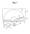
- the wiper device has a motor as Drive 10, on a connection shown in dashed lines 12, for example a transmission, a wiper 14 drives.
- the wiper 14 has a wiper blade 16, with the one pane 18 in the area of a wiping field 20 between two reversal positions U1, U2 is wiped.
- the engine 10 by a controller 25 in different wiping operations controlled, which in turn by a switch 24 manually can be specified.
- the control of the Wipe operation possible due to signals from a rain sensor.
- the controller 25 receives a temperature signal S, which is already in the electronics of many vehicles is available. Of course, a simple one can Thermometer, which is placed in a suitable place is to convey the temperature signal S to the controller 25.
- the wiper 14 is moved into a parking position P when the Wiping operation of the wiper 14 switched off or at one Intermittent operation is interrupted. In the latter the Wiper 14 between the individual wiping cycles of the interval operation parked in the parking area P.
- This parking position P is located usually close to the lower edge of the disk 18 the window bezel 30.
- a reversing motor is used as the motor 10, for example via a rotatable engine crank, not shown and a pendulum gear as connection 12 oscillating the wiper 14 drives.
- connection 12 oscillating the wiper 14 drives.
- FIG. 2a shows a first
- FIG. 2b shows a second parking position
- P1, P2 of the wiper blade 16 in the park position P Das Wiper blade 16 is fastened to wiper 14 in a holder 26.
- a wiper lip 28 is formed on the wiper blade 16. The wiper lip is in the first parking position of the window frame 30 facing away, in the second parking position P2 executed to this.
- An axis of symmetry 32 of the wiper blade 16 in the unloaded Condition is also shown. The following is this Position of the wiper blade 16 defined by the axis of symmetry 32.
- the wiper 14 is in the Parking position P when the axis of symmetry 32 and the parking position P are congruent.
- FIG. 3 the folding process of the wiper blade 16 to Approaching the second parking position P2 shown.
- the wiper lip 28 is via a transfer web 34 with the wiper blade 16 connected.
- the operation of the device according to the invention 1 is shown in the following according to FIGS. 2 and 3 described.
- the wiper device for Windows 18 of vehicles, especially motor vehicles, wipes the window 18, for example, in a continuous wiping operation. After operating the control switch 24 to switch off of the wiping operation, the controller 22 of the Wiper blade 16 in the park position P.
- Position X1 marks any one Position of the wiper blade 16 within the wiping field 20 in front of the park position P. While wiping is the wiper lip 28 kinked against the wiping direction. Moves for example wiper blade 16 to the right, then is the wiper lip 28 bent to the left. The location of the wiper lip 28 is referred to below as the first towing position, because it is dragged along by the wiper blade 16. Reached the wiper blade 16 the parking position P, then the motor 10 turned off and the wiper lip 28 is in the first parking position P1 that of the first drag position of the wiper lip 28 corresponds.
- the alternate placement of the wiper lip 28 in the two Parking positions P1, P2 are realized by the controller 25.
- This has a non-volatile memory and one Timer 29 on.
- you can't in this volatile memory also stored other presets such as the last parking position taken up P1 or P2 and / or at what time the temperature signal to be evaluated by the controller 25.
- an integrated temperature signal can also be used here saved for dynamic parking position change his.
- This integrated signal then runs with every temperature measurement, which happens every quarter of an hour, high until a predetermined value is reached. Then is changed from the parking position P1 to P2 - or vice versa and reset the integrated signal. In in this case no timer 29 is then required either the time interval is determined virtually dynamically.
- a temperature signal S is recorded by the controller 25 become.
- the controller 25 based on the time interval, the size of the temperature signal S, after its expiration, the control 25, the wiper lip 28 in the other parking position P1, P2 changes.
- the time signal is the temperature signal each time the vehicle is started newly queried and the remaining after each measurement Time after one set in the non-volatile memory Algorithm corrected.
- the temperature signal S is also possible, for example to be queried every 5th, 10th or nth start or to be queried before every nth parking position change.
Landscapes
- Engineering & Computer Science (AREA)
- Mechanical Engineering (AREA)
- Automation & Control Theory (AREA)
- Regulating Braking Force (AREA)
- Control Of Electric Motors In General (AREA)
- Vehicle Cleaning, Maintenance, Repair, Refitting, And Outriggers (AREA)
Applications Claiming Priority (2)
| Application Number | Priority Date | Filing Date | Title |
|---|---|---|---|
| DE2000149187 DE10049187A1 (de) | 2000-10-05 | 2000-10-05 | Wischvorrichtung sowie Verfahren zum Betreiben der Wischvorrichtung |
| DE10049187 | 2000-10-05 |
Publications (3)
| Publication Number | Publication Date |
|---|---|
| EP1195301A2 true EP1195301A2 (fr) | 2002-04-10 |
| EP1195301A3 EP1195301A3 (fr) | 2004-03-10 |
| EP1195301B1 EP1195301B1 (fr) | 2005-11-02 |
Family
ID=7658682
Family Applications (1)
| Application Number | Title | Priority Date | Filing Date |
|---|---|---|---|
| EP20010122351 Expired - Lifetime EP1195301B1 (fr) | 2000-10-05 | 2001-09-19 | Dispositif d'essuie-glace et procédé de commande du dispositif |
Country Status (3)
| Country | Link |
|---|---|
| EP (1) | EP1195301B1 (fr) |
| DE (2) | DE10049187A1 (fr) |
| ES (1) | ES2248209T3 (fr) |
Cited By (3)
| Publication number | Priority date | Publication date | Assignee | Title |
|---|---|---|---|---|
| EP1334889A3 (fr) * | 2002-02-08 | 2004-04-14 | Audi Ag | Dispositif d'essuie-glace pour véhicule |
| EP1783017A2 (fr) | 2005-11-05 | 2007-05-09 | GM Global Technology Operations, Inc. | Méthode de positionnement d'un essuie-glace et véhicule lié à cet essuie-glace |
| WO2012019924A1 (fr) * | 2010-08-10 | 2012-02-16 | Robert Bosch Gmbh | Commande d'essuie-glace |
Families Citing this family (2)
| Publication number | Priority date | Publication date | Assignee | Title |
|---|---|---|---|---|
| DE102007059070A1 (de) | 2007-01-11 | 2008-07-17 | Volkswagen Ag | Scheibenwischeranlage mit einem Rundläufermotor als Antriebsmotor |
| DE102009032506A1 (de) | 2009-07-09 | 2010-02-11 | Daimler Ag | Verfahren zum Betrieb einer Scheibenwischanlage eines Fahrzeugs |
Citations (1)
| Publication number | Priority date | Publication date | Assignee | Title |
|---|---|---|---|---|
| DE19733426A1 (de) | 1997-08-01 | 1999-02-04 | Bosch Gmbh Robert | Wischvorrichtung für Scheiben von Fahrzeugen |
Family Cites Families (4)
| Publication number | Priority date | Publication date | Assignee | Title |
|---|---|---|---|---|
| JPS58174046A (ja) * | 1982-04-07 | 1983-10-13 | Daihatsu Motor Co Ltd | ウインドの霜付防止装置 |
| DE3627561C1 (en) * | 1986-08-14 | 1987-10-22 | Audi Ag | Process for operating a screen-wiper system for motor vehicles |
| DE3637921A1 (de) * | 1986-11-06 | 1988-05-19 | Swf Auto Electric Gmbh | Wischanlage fuer kraftfahrzeuge |
| JPH0930374A (ja) * | 1995-07-21 | 1997-02-04 | Honda Motor Co Ltd | 車両用ワイパー装置 |
-
2000
- 2000-10-05 DE DE2000149187 patent/DE10049187A1/de not_active Withdrawn
-
2001
- 2001-09-19 DE DE50107897T patent/DE50107897D1/de not_active Expired - Lifetime
- 2001-09-19 EP EP20010122351 patent/EP1195301B1/fr not_active Expired - Lifetime
- 2001-09-19 ES ES01122351T patent/ES2248209T3/es not_active Expired - Lifetime
Patent Citations (1)
| Publication number | Priority date | Publication date | Assignee | Title |
|---|---|---|---|---|
| DE19733426A1 (de) | 1997-08-01 | 1999-02-04 | Bosch Gmbh Robert | Wischvorrichtung für Scheiben von Fahrzeugen |
Cited By (5)
| Publication number | Priority date | Publication date | Assignee | Title |
|---|---|---|---|---|
| EP1334889A3 (fr) * | 2002-02-08 | 2004-04-14 | Audi Ag | Dispositif d'essuie-glace pour véhicule |
| EP1783017A2 (fr) | 2005-11-05 | 2007-05-09 | GM Global Technology Operations, Inc. | Méthode de positionnement d'un essuie-glace et véhicule lié à cet essuie-glace |
| EP1783017A3 (fr) * | 2005-11-05 | 2008-06-25 | GM Global Technology Operations, Inc. | Méthode de positionnement d'un essuie-glace et véhicule lié à cet essuie-glace |
| WO2012019924A1 (fr) * | 2010-08-10 | 2012-02-16 | Robert Bosch Gmbh | Commande d'essuie-glace |
| US8957619B2 (en) | 2010-08-10 | 2015-02-17 | Robert Bosch Gmbh | Wiper control |
Also Published As
| Publication number | Publication date |
|---|---|
| ES2248209T3 (es) | 2006-03-16 |
| DE10049187A1 (de) | 2002-04-11 |
| EP1195301A3 (fr) | 2004-03-10 |
| DE50107897D1 (de) | 2005-12-08 |
| EP1195301B1 (fr) | 2005-11-02 |
Similar Documents
| Publication | Publication Date | Title |
|---|---|---|
| DE102006061679B4 (de) | Vorrichtung und Verfahren zur Ansteuerung einer Antriebseinheit einer Wischanlage | |
| DE69919837T2 (de) | Scheibenwischervorrichtung und Verfahren zur variablen Einstellung der Bewegung des Wischblatts | |
| DE102009044819A1 (de) | Scheibenwischersystem und Scheibenwischersteuerverfahren | |
| DE102009047211A1 (de) | Steuervorrichtung und Steuerverfahren für die Antriebseinheit einer Scheibenwischanlage | |
| EP0999960B1 (fr) | Dispositif essuie-glace pour vehicules | |
| DE102008042591A1 (de) | Motorsteuergerät | |
| WO1997033780A1 (fr) | Balai d'essuie-glace pour vitres de vehicules a moteur | |
| EP2243671B1 (fr) | Balai d'essuie-glace et système d'essuie-glace | |
| DE3630205A1 (de) | Fahrzeugscheibenwischer mit einstellbarer anpresskraft fuer ein wischerblatt | |
| EP2274184B1 (fr) | Procédé de montage d'un bras d'essuie-glace, procédé d'ajustement ou d'opération d'un dispositif d'essuie-glace et un dispositif d'essuie-glace | |
| EP1289803B1 (fr) | Bras d'essuie-glace a quatre articulations | |
| EP1195301A2 (fr) | Dispositif d'essuie-glace et procédé de commande du dispositif | |
| EP2467283B1 (fr) | Dispositif d'essuie-glace | |
| DE2647510A1 (de) | Kurbel zum antrieb eines scheibenwischergestaenges | |
| DE102005062695A1 (de) | Verfahren zum Einstellen des Wischwinkels bei einer Wischanlage mit Reversiermotor für eine Fahrzeugscheibe | |
| DE202017106396U1 (de) | Ausziehbares Scheibenwischersystem | |
| EP0317767A1 (fr) | Dispositif essuie-glace | |
| EP2733026A2 (fr) | Bras d'essuie-glace doté d'un actionneur | |
| DE102005045921B4 (de) | Verfahren zum Wischen einer Scheibe sowie Scheibenwischvorrichtung, insbesondere für ein Kraftfahrzeug | |
| DE102013216883A1 (de) | Scheibenwischervorrichtung für ein Kraftfahrzeug und Verfahren dafür | |
| DE102007061744A1 (de) | Scheibenwischvorrichtung | |
| DE10245662A1 (de) | Scheibenwischvorrichtung | |
| DE3329573A1 (de) | Scheibenwischeranlage fuer kraftfahrzeuge | |
| DE10032048A1 (de) | Wischblatt für Scheiben, insbesondere von Kraftfahrzeugen, sowie Verfahren zum Herstellen eines solchen | |
| WO2024149543A1 (fr) | Procédé et dispositif d'assistance pour estimation de vitesse d'écoulement d'air incident d'un véhicule automobile, et véhicule à moteur configuré en conséquence |
Legal Events
| Date | Code | Title | Description |
|---|---|---|---|
| PUAI | Public reference made under article 153(3) epc to a published international application that has entered the european phase |
Free format text: ORIGINAL CODE: 0009012 |
|
| AK | Designated contracting states |
Kind code of ref document: A2 Designated state(s): AT BE CH CY DE DK ES FI FR GB GR IE IT LI LU MC NL PT SE TR |
|
| AX | Request for extension of the european patent |
Free format text: AL;LT;LV;MK;RO;SI |
|
| PUAL | Search report despatched |
Free format text: ORIGINAL CODE: 0009013 |
|
| AK | Designated contracting states |
Kind code of ref document: A3 Designated state(s): AT BE CH CY DE DK ES FI FR GB GR IE IT LI LU MC NL PT SE TR |
|
| AX | Request for extension of the european patent |
Extension state: AL LT LV MK RO SI |
|
| 17P | Request for examination filed |
Effective date: 20040910 |
|
| AKX | Designation fees paid |
Designated state(s): DE ES FR GB IT |
|
| GRAP | Despatch of communication of intention to grant a patent |
Free format text: ORIGINAL CODE: EPIDOSNIGR1 |
|
| GRAS | Grant fee paid |
Free format text: ORIGINAL CODE: EPIDOSNIGR3 |
|
| GRAA | (expected) grant |
Free format text: ORIGINAL CODE: 0009210 |
|
| AK | Designated contracting states |
Kind code of ref document: B1 Designated state(s): DE ES FR GB IT |
|
| REG | Reference to a national code |
Ref country code: GB Ref legal event code: FG4D Free format text: NOT ENGLISH |
|
| REF | Corresponds to: |
Ref document number: 50107897 Country of ref document: DE Date of ref document: 20051208 Kind code of ref document: P |
|
| GBT | Gb: translation of ep patent filed (gb section 77(6)(a)/1977) |
Effective date: 20060215 |
|
| REG | Reference to a national code |
Ref country code: ES Ref legal event code: FG2A Ref document number: 2248209 Country of ref document: ES Kind code of ref document: T3 |
|
| ET | Fr: translation filed | ||
| PLBE | No opposition filed within time limit |
Free format text: ORIGINAL CODE: 0009261 |
|
| STAA | Information on the status of an ep patent application or granted ep patent |
Free format text: STATUS: NO OPPOSITION FILED WITHIN TIME LIMIT |
|
| 26N | No opposition filed |
Effective date: 20060803 |
|
| PGFP | Annual fee paid to national office [announced via postgrant information from national office to epo] |
Ref country code: GB Payment date: 20100924 Year of fee payment: 10 |
|
| PGFP | Annual fee paid to national office [announced via postgrant information from national office to epo] |
Ref country code: IT Payment date: 20100928 Year of fee payment: 10 |
|
| GBPC | Gb: european patent ceased through non-payment of renewal fee |
Effective date: 20110919 |
|
| PG25 | Lapsed in a contracting state [announced via postgrant information from national office to epo] |
Ref country code: IT Free format text: LAPSE BECAUSE OF NON-PAYMENT OF DUE FEES Effective date: 20110919 |
|
| PG25 | Lapsed in a contracting state [announced via postgrant information from national office to epo] |
Ref country code: GB Free format text: LAPSE BECAUSE OF NON-PAYMENT OF DUE FEES Effective date: 20110919 |
|
| PGFP | Annual fee paid to national office [announced via postgrant information from national office to epo] |
Ref country code: DE Payment date: 20121122 Year of fee payment: 12 |
|
| PGFP | Annual fee paid to national office [announced via postgrant information from national office to epo] |
Ref country code: ES Payment date: 20130923 Year of fee payment: 13 |
|
| PGFP | Annual fee paid to national office [announced via postgrant information from national office to epo] |
Ref country code: FR Payment date: 20130918 Year of fee payment: 13 |
|
| REG | Reference to a national code |
Ref country code: DE Ref legal event code: R119 Ref document number: 50107897 Country of ref document: DE Effective date: 20140401 |
|
| PG25 | Lapsed in a contracting state [announced via postgrant information from national office to epo] |
Ref country code: DE Free format text: LAPSE BECAUSE OF NON-PAYMENT OF DUE FEES Effective date: 20140401 |
|
| REG | Reference to a national code |
Ref country code: FR Ref legal event code: ST Effective date: 20150529 |
|
| PG25 | Lapsed in a contracting state [announced via postgrant information from national office to epo] |
Ref country code: FR Free format text: LAPSE BECAUSE OF NON-PAYMENT OF DUE FEES Effective date: 20140930 |
|
| REG | Reference to a national code |
Ref country code: ES Ref legal event code: FD2A Effective date: 20151027 |
|
| PG25 | Lapsed in a contracting state [announced via postgrant information from national office to epo] |
Ref country code: ES Free format text: LAPSE BECAUSE OF NON-PAYMENT OF DUE FEES Effective date: 20140920 |