EP1194083B1 - Logarithmic light intensifier for use with photoreceptor-based implanted retinal prosthetics and those prosthetics - Google Patents
Logarithmic light intensifier for use with photoreceptor-based implanted retinal prosthetics and those prosthetics Download PDFInfo
- Publication number
- EP1194083B1 EP1194083B1 EP00917743A EP00917743A EP1194083B1 EP 1194083 B1 EP1194083 B1 EP 1194083B1 EP 00917743 A EP00917743 A EP 00917743A EP 00917743 A EP00917743 A EP 00917743A EP 1194083 B1 EP1194083 B1 EP 1194083B1
- Authority
- EP
- European Patent Office
- Prior art keywords
- image
- eye
- light
- retinal
- photoreceptor
- Prior art date
- Legal status (The legal status is an assumption and is not a legal conclusion. Google has not performed a legal analysis and makes no representation as to the accuracy of the status listed.)
- Expired - Lifetime
Links
- 230000002207 retinal effect Effects 0.000 title claims abstract description 59
- 108091008695 photoreceptors Proteins 0.000 title claims abstract description 56
- 230000003287 optical effect Effects 0.000 claims abstract description 10
- 230000002051 biphasic effect Effects 0.000 claims abstract description 9
- 210000001525 retina Anatomy 0.000 claims abstract description 7
- 210000005036 nerve Anatomy 0.000 claims description 8
- 230000000007 visual effect Effects 0.000 claims description 8
- 238000012546 transfer Methods 0.000 claims description 4
- 230000006835 compression Effects 0.000 claims description 3
- 238000007906 compression Methods 0.000 claims description 3
- 230000002708 enhancing effect Effects 0.000 claims description 2
- 230000004936 stimulating effect Effects 0.000 claims 1
- 230000000638 stimulation Effects 0.000 abstract description 34
- 230000004456 color vision Effects 0.000 abstract description 9
- 238000003199 nucleic acid amplification method Methods 0.000 abstract description 9
- 230000003321 amplification Effects 0.000 abstract description 8
- 230000002596 correlated effect Effects 0.000 abstract description 3
- 238000003384 imaging method Methods 0.000 abstract description 3
- 238000002347 injection Methods 0.000 abstract description 3
- 239000007924 injection Substances 0.000 abstract description 3
- 201000004569 Blindness Diseases 0.000 abstract description 2
- 230000006735 deficit Effects 0.000 abstract description 2
- 230000004438 eyesight Effects 0.000 abstract description 2
- 230000003213 activating effect Effects 0.000 abstract 1
- 239000003086 colorant Substances 0.000 abstract 1
- 239000000463 material Substances 0.000 abstract 1
- 210000004027 cell Anatomy 0.000 description 40
- 239000007943 implant Substances 0.000 description 17
- 239000012530 fluid Substances 0.000 description 7
- 230000006870 function Effects 0.000 description 7
- 230000006378 damage Effects 0.000 description 6
- 210000001747 pupil Anatomy 0.000 description 6
- 230000000875 corresponding effect Effects 0.000 description 5
- 238000012545 processing Methods 0.000 description 5
- 230000005540 biological transmission Effects 0.000 description 4
- 230000009977 dual effect Effects 0.000 description 4
- 238000010348 incorporation Methods 0.000 description 4
- 238000000034 method Methods 0.000 description 4
- 230000008447 perception Effects 0.000 description 4
- 238000011084 recovery Methods 0.000 description 4
- 230000008901 benefit Effects 0.000 description 3
- 210000004556 brain Anatomy 0.000 description 2
- 210000003986 cell retinal photoreceptor Anatomy 0.000 description 2
- 230000001427 coherent effect Effects 0.000 description 2
- 238000013507 mapping Methods 0.000 description 2
- 210000001328 optic nerve Anatomy 0.000 description 2
- 230000008569 process Effects 0.000 description 2
- 238000002310 reflectometry Methods 0.000 description 2
- 201000007737 Retinal degeneration Diseases 0.000 description 1
- 206010047571 Visual impairment Diseases 0.000 description 1
- 238000010521 absorption reaction Methods 0.000 description 1
- 230000009471 action Effects 0.000 description 1
- 238000012884 algebraic function Methods 0.000 description 1
- 239000000969 carrier Substances 0.000 description 1
- 230000007248 cellular mechanism Effects 0.000 description 1
- 239000002800 charge carrier Substances 0.000 description 1
- 238000006243 chemical reaction Methods 0.000 description 1
- 230000000295 complement effect Effects 0.000 description 1
- 230000007423 decrease Effects 0.000 description 1
- 230000003247 decreasing effect Effects 0.000 description 1
- 238000013461 design Methods 0.000 description 1
- 230000000694 effects Effects 0.000 description 1
- 239000011521 glass Substances 0.000 description 1
- 238000002513 implantation Methods 0.000 description 1
- 230000007257 malfunction Effects 0.000 description 1
- 230000007246 mechanism Effects 0.000 description 1
- 239000000203 mixture Substances 0.000 description 1
- 238000012986 modification Methods 0.000 description 1
- 230000004048 modification Effects 0.000 description 1
- 230000000737 periodic effect Effects 0.000 description 1
- 230000010363 phase shift Effects 0.000 description 1
- 230000004044 response Effects 0.000 description 1
- 230000004258 retinal degeneration Effects 0.000 description 1
- 230000035807 sensation Effects 0.000 description 1
- 238000007493 shaping process Methods 0.000 description 1
- 208000029257 vision disease Diseases 0.000 description 1
- 230000004393 visual impairment Effects 0.000 description 1
Images


Classifications
-
- A—HUMAN NECESSITIES
- A61—MEDICAL OR VETERINARY SCIENCE; HYGIENE
- A61N—ELECTROTHERAPY; MAGNETOTHERAPY; RADIATION THERAPY; ULTRASOUND THERAPY
- A61N1/00—Electrotherapy; Circuits therefor
- A61N1/18—Applying electric currents by contact electrodes
- A61N1/32—Applying electric currents by contact electrodes alternating or intermittent currents
- A61N1/36—Applying electric currents by contact electrodes alternating or intermittent currents for stimulation
- A61N1/36046—Applying electric currents by contact electrodes alternating or intermittent currents for stimulation of the eye
-
- A—HUMAN NECESSITIES
- A61—MEDICAL OR VETERINARY SCIENCE; HYGIENE
- A61F—FILTERS IMPLANTABLE INTO BLOOD VESSELS; PROSTHESES; DEVICES PROVIDING PATENCY TO, OR PREVENTING COLLAPSING OF, TUBULAR STRUCTURES OF THE BODY, e.g. STENTS; ORTHOPAEDIC, NURSING OR CONTRACEPTIVE DEVICES; FOMENTATION; TREATMENT OR PROTECTION OF EYES OR EARS; BANDAGES, DRESSINGS OR ABSORBENT PADS; FIRST-AID KITS
- A61F9/00—Methods or devices for treatment of the eyes; Devices for putting in contact-lenses; Devices to correct squinting; Apparatus to guide the blind; Protective devices for the eyes, carried on the body or in the hand
- A61F9/08—Devices or methods enabling eye-patients to replace direct visual perception by another kind of perception
Definitions
- This invention relates generally to retinal prosthetics and more particularly to an apparatus for enhancing retinal prosthetic performance.
- This invention relates to directly modulating a beam of photons of sufficient energy onto retinal prosthetic implants of patients who have extreme vision impairment or blindness.
- a healthy eye is has photosensitive retinal cells (e.g. rods and cones) which react to specific wavelengths of light to trigger nerve impulses. Complex interconnections among the retinal nerves assemble these impulses which are carried through the optic nerve to the visual centers of the brain, where they are interpreted. Certain forms of visual impairment are primarily attributable to a malfunction of the photosensitive retinal cells. In such cases, sight may be enhanced by a retinal prosthesis implanted in a patient's eye. Michelson (U.S. Patent No.4, 628,933) and Chow (U.S. Patent Nos.
- 5,016,633; 5,397,350; 5,556,423) teach a retinal implant, or implants, of essentially photoreceptors facing out of the eye toward the pupil, each with an electrode which can stimulate a bipolar, or similar, cell with an electrical impulse. This bipolar cell is acted upon by the electrical stimulus, to send appropriate nerve impulses essentially through the optic nerve, to the brain.
- This invention is postulated as a necessary complement to this type of prosthesis, because the photoreceptors do not appear to be sensitive enough to the ordinary levels of light entering the eye in that not enough current is produced to sufficiently stimulate the retinal cells. Consequently, a light amplifier, or "helper” device would be needed. That device is the invention herein described, which also includes special characteristic implants.
- a direct retinal scan display including the steps of providing a directed beam of light, modulating the beam of light to impress video information onto the beam of light, deflecting the beam in two orthogonal directions, providing a planar imager including an input for receiving a beam of light into the eye of an operator which involves a redirection diffractive optical element for creating a virtual image from the beam of light on the retina of the eye, and directing the beam of light scanned in two orthogonal directions and modulated into the input of the planar imager and the output of the planar imager into the eye of an operator.”
- the present invention is directed to an apparatus for providing enhanced retinal prosthetic performance. More particularly, the invention is directed to a light amplifier and electrical circuitry for driving an implanted retinal prosthesis to maximize electrical stimulation of the retinal nerves or cells, while avoiding damage thereto. The invention is also directed to improved implanted retinal prostheses, which maximize the advantages of the light amplifier.
- light reflected from a viewed image i.e., input image
- a light amplifier to produce an output image which is applied to the photoreceptor array of a retinal prosthesis.
- the gain (or "transfer function") of the light amplifier enables the photoreceptor array to drive output electrodes for producing retinal nerve impulses of sufficient magnitude to enhance perceived sight.
- the light amplifier compresses the range of light intensity logarithmically, to enable maximum light amplification without overdriving the prosthetic photoreceptors.
- the electrical stimulation of the retinal nerves is preferably pulsed, i.e., periodically interrupted to avoid any damage attributable to peak magnitude electrical signals.
- Periodic interruption can be implemented mechanically by a shutter periodically interrupting the light incident on the photoreceptor array and/or electrically via an appropriate wave shaping circuit.
- the implanted prosthetic's electrodes generate a sequence of positive and negative pulses to avoid producing a net charge in the eye. Successive pulses are preferably spaced in time by an interval ⁇ t.
- a single wavelength is relied upon to activate a combined photodetector-electronics-electrode implanted unit which then produces a negative pulse, followed by a time delay, followed by a positive pulse.
- a photoreceptor implanted in the eye acts to produce an electrical stimulation with an equal amount of positive and negative charge.
- a single light wavelength is received by the photoreceptor. That single wavelength contains extractable energy. It also contains information, which may be encoded by amplitude modulation, frequency modulation, phase shift methods or pulse width modulation, for example.
- the photoreceptor activates an electrode with associated electronics. The electronics produces a negative pulse followed by a time delay followed by a positive pulse.
- a net charge of zero is introduced into the eye by the electrode-originating electrical pulses.
- the preferred delay time is in the range 0.1 millisecond to 10 milliseconds, with the delay time of 2 milliseconds is most preferred.
- a first wavelength is used to stimulate a first set of "electronic" photoreceptors. These photoreceptors are connected so that the stimulation of the attached, or associated, electrodes results in a negative pulse. This negative pulse provides retinal cell stimulation. Then the shutter cuts in and stops light transmission to the eye. The retinal cell is in a rest and recovery state so that it returns, electrically, to the state it was in prior to stimulation by the first particular wavelength of light. A second particular wavelength of light then stimulates a second set of photoreceptors which are sensitive to that wavelength of light; while the first set of photoreceptors are not affected.
- This second set of photoreceptors is connected so that the stimulation of the attached, or associated, electrodes results in a positive pulse.
- the net charge introduced into the retinal cells must balance. So the positive charge introduced by the positive pulse must equal the negative charge introduced by the negative pulse.
- the shutter cuts in and stops light transmission. Again, the retinal cells rest and recover and the process repeats.
- An aspect of the second embodiment is using an electro-optic, electronic or mechanical shutter to provide a period of no electrical stimulation to the retinal cells targeted for electrical stimulation.
- a third embodiment which is a cross, so to speak, between the first and second embodiments two different wavelengths and two different types of diodes, each responsive to a corresponding wavelength are used.
- one wavelength is used to pump in a high constant level of light to supply power to the electronics component.
- the other wavelength is used to send in information via amplitude, frequency, phase, pulse-width modulation, or combinations thereof.
- the stimulation pulse from the electronics to the electrode to the retinal cell is generated in a fashion similar to the pulses generated in the first embodiment, with a single wavelength.
- a fourth embodiment is that of the logarithmic light amplifier itself, without any special implantable photoreceptors.
- This last embodiment may require a low duty cycle when used with photoreceptors connected to a diode without any electronics. It may be able to rely sufficiently upon the intrinsic capacitance of an oxidizable electrode, which acquires capacitance with the buildup of an insulating oxidized layer toward the ionizable fluid present in the eye as vitreous fluid, or fluid directly associated with the eye.
- An image receiver with a first converter for the image converts the image into electrical signals.
- the signals are amplified, basically logarithmically, so as to provide brightness compression for the patient.
- An aspect of the embodiments of the invention is that an amplified electrical signal is converted by a second converter into a photon-based display; the photons of this display enter an eye through the pupil of the eye.
- the embodiments of the logarithmic amplifier invention have sufficient output light power, advantageously, the output light level still remains at a safe level.
- This aspect of the invention corresponds to aspects of the action of the iris, as well as the biochemistry of retinal cells, in the human eye in making possible sight over many orders of magnitude of ambient brightness.
- An aspect of the embodiments of the invention is incorporation of both optical and electronic magnification of the image, as for example, the incorporation of an optical zoom lens, as well as electronic magnification. Consequently, it is feasible to focus in on items of particular interest or necessity.
- Another aspect of the invention is oriented toward making color vision available, at least to a degree.
- individual stimulation sites e.g., retinal cells generally, bipolar cells specifically
- the color of selected pixels of the viewed scene is correlated with a specific photoreceptor-electronics-electrode units located so as to electrically stimulate a specific type of bipolar cell to provide the perception of color vision.
- the logarithmic light amplifier also incorporates within itself, a data processing unit which, semi-autonomously, cycles through the various photodetector-electrode and combinations thereof, interrogates the patient as to what the patient sees, the patient then supplies the answers, setting up proper apparent brightness, proper apparent color and proper perception.
- This setup mode is done by the use of a keyboard, display, and auxiliary processor, which are plugged into the data processing unit of the logarithmic light amplifier during the setup procedure.
- a scanning laser feedback is provided in different embodiments of the invention to keep the scanner laser scanning the correct locations.
- An imaging of the reflected scanning laser reflected back from the retinal implant is used to provide real-time feedback information, utilizing a second imager viewing into the eye and a data processor unit tied into the scanning laser scan control unit.
- This invention provides amplified light for artificial photoreceptors implanted in the eye of a patient who has lost the use of his/her normal photoreceptor retinal cells.
- the purpose of this amplified light is to effectively stimulate the artificial photoreceptors.
- the artificial photoreceptors provide electrical stimulation through associated electrodes, usually via some electronics, to retinal cells, which are normally stimulated by living retinal photoreceptors such as cones and rods.
- the retinal cells which get electrically stimulated by way of the artificial photoreceptors, are typically bipolar cells. This stimulation to these non-photoreceptor retinal cells allows the patient to have at least some perception of what a normal eye would see.
- light is fed to the photoreceptor-electrode stimulators in the following ways.
- a single wavelength is relied upon to activate a combined photodetector-electronics-electrode implanted unit which then produces a negative pulse, followed by a time delay, followed by a negative pulse.
- a photoreceptor implanted in the eye acts to produce an electrical stimulation with an equal amount of positive and negative charge.
- a single light wavelength is received by the photoreceptor.
- the photoreceptor activates an electrode with associated electronics.
- the electronics produces a negative pulse followed by a time delay followed by a positive pulse.
- a net charge of zero is introduced into the eye by the electrode-originating electrical pulses.
- the preferred delay time is in the range 0.1 millisecond to 10 milliseconds, with the delay time of 2 milliseconds is most preferred.
- an image receiver With a first converter for the image, converts the image into electrical signals.
- the signals are amplified, basically logarithmically, so as to provide brightness compression for the patient.
- the amplified electrical signal is converted by a second converter into a photon-based display; wherein said photons of said display enter an eye through a pupil of said eye.
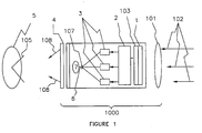
- the light amplifier (1000) has an image receiver (1), a first converter (103) of the image into electrical signals, an amplifier (2) of said electrical signals whereby the overall amplification of said electrical signal according to a definite functional relationship between input signal to the amplifier and an output signal from the amplifier, a second converter (107) of said amplified electrical signal into a photon-based display (7); such that the of display photons (108) enter an eye (5) through the pupil (105) of the eye (5).
- the imager (1) is a type of video camera
- the image receiver and conversion to electrical signals may occur in a package (old in the art).
- a display (7) that is a source of photons such as a laser (coherent light source) (7), or a non-coherent source such as colored LEDs (7), or a plasma display (7), is used to send photons directly to an implant near the retina.
- These displays (7) are made very bright, but not such as to impact negatively on the eye. In our cases, the patient has sufficient retinal degeneration so as to be unable to see without the aid of a retinal prosthetic.
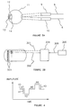
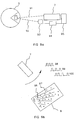
- the display (photon source) is a laser (7), that laser is scanned over the implanted photodetector-electronics-electrode array ( Figure 2, (8) in accordance with the scene being displayed to the eye.
- a scanning laser is a laser with scanning means (old in the art).
- the video signal (6) is applied to a scanning laser (7), a scanning laser being a laser with scanning means (old in the art).
- the scanning laser (7) is scanned over the retinal prosthesis in a square or rectangular pattern or in a raster pattern with an exact fit to the prosthesis (8).
- the video signal (6) supplies amplitude from the data processor ( Figure 1, (2)), and if desired (see Figure 1), color information, of the scene being viewed, from the individual color amplifiers (3) to the laser (7), which information is used to modulate the laser.
- the light amplifier (1000) is a logarithmic amplifier.
- the amplifier amplifies according to a different function than the logarithmic function or a modified logarithmic function, for example, an algebraic function such as a polynomial function multiplied by the logarithmic function
- the imager or camera lens is shown schematically as (101).
- the signal is logarithmically amplified as a whole at the electronic processor (2), or the individual RGB (red, green, blue) or RGBY (red, green, blue, yellow) color components are individually logarithmically amplified (3). Another color component mix of white light may be used.
- the individual amplification (3) of separate color components allows for the relative super-amplification of one color to which the photoreceptors are particularly sensitive. If only a "black-and-white" contrast image is displayed, the "white” part of that image is logarithmically translated to the color, i.e.. wavelength, to which the photoreceptors are most sensitive.
- This feature includes shifting the wavelength toward or to the near infrared or toward or to the near ultraviolet, according to what is needed to optimize the response of the implanted photosensitive elements. Consequently, a mapping of the incoming image data to an appropriate output is possible.
- This mapping could be complex, for example, producing biphasic waveforms as shown in Figure 4 by appropriate timing of two lasers operating at different wavelengths and photosensitive elements uniquely sensitive to these wavelengths.
- RGB red, green, blue
- RGBY red, green, blue, yellow
- the logarithmic amplification is necessary to compress the range of original brightness.
- the normal eye does this automatically of closing down the pupil size, squinting and employing other electrochemical cellular mechanisms.
- This light amplifier accomplishes this necessary task by electronic logarithmic light amplification.
- the light amplifier also includes an adjustable transformer or magnification of image size. A shutter or electronically turning the scanning laser on and off are not a necessary part of this embodiment.
- two or more wavelengths are used to communicate light energy to the eye to allow balanced biphasic stimulation with no net charge injection into the eye.
- a first wavelength is used to stimulate a first set of photoreceptors. These photoreceptors are connected so that the stimulation of the attached, or associated, electrodes results in a negative pulse. This negative pulse provides retinal cell stimulation. Then the shutter cuts in and stops light transmission to the eye. The time of this light interruption is preferred in the range 0.1 millisecond to 10 milliseconds, with the time of 2 milliseconds most preferred.
- the retinal cell is in a rest and recovery state so that it returns, electrically, to the state it was in prior to stimulation by the first particular wavelength of light.
- a second wavelength of light then stimulates a second set of photoreceptors which are sensitive to that wavelength of light; while the first set of photoreceptors are not affected.
- This second set of photoreceptors is connected so that the stimulation of the attached, or associated, electrodes results in a positive pulse.
- the net charge introduced into the retinal cells must balance, or equal, the net charge introduced by the negative pulse.
- the shutter cuts in and stops light transmission. Again, the retinal cells rest and recover and the process repeats.
- FIG. 3A two scanning lasers, (9) and (10), are supplied with video signals, with each laser operating at a different wavelength.
- two or more photoreceptors (13), (14) are on the implant.
- the two types of photoreceptors (13), (14), are tuned to different frequencies of light, each of the frequencies being that of one of the emitting frequencies of the external lasers (9), (10).
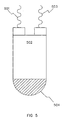
- Figure 3B shows two incoming frequencies of light, (301) and (302).
- the light sources for the dual light frequencies (301), (302) is a unit (304) which is downstream in the information flow from the imager ( Figure 1, (101), (1), (103)) and amplifiers ( Figure 1, (2), (3)).
- the final output from the amplification stages is connected electrically or electromagnetically to the dual light frequency sources (304), in particular, dual scanning lasers operating with different wavelengths of light output. Pairs (303) of different frequency (i.e., wavelength) photoreceptors are placed on the eye-implant, each pair associated with an electrode (not shown).
- a shutter (4) is part of the second embodiment.
- the shutter ( Figure 1, (4)) is of a mechanical design (old in the art), or an electronic shutter (4) (old in the art) or an electro-optical shutter (4) (old in the art).
- the shutter (4) cuts off light from the logarithmic light amplifier (1000) to the pupil (105) of the eye (5). This decreases the total time that light strikes the photoreceptors ( Figure 3a, (13). (14)), ( Figure 3b, 303) Consequently, the time during which the bipolar, or similar cells, are stimulated is decreased. Because the eye is not functioning as originally intended, the bipolar, or similar, cells are thought to need this "down-time" to continue to function properly.
- An aspect of this invention is the use of two or more wavelengths to allow balanced biphasic stimulation with no net charge injection into the eye.
- a biphasic type of electrical stimulation where equal amounts of positive charge and negative charge in the form of ionic carriers or electrons or other charge carriers, enter the vitreous fluid of the eye, the electrical effect on the eye is not harmful. If direct current is supplied to the eye, internally, a charge imbalance results. This excess of charge has been found to be harmful to cells. Consequently, direct current can harm the bipolar and other cells.
- the biphasic electrical stimulation tends to avoid this harm to the cells because no excess charge accumulates.
- a third embodiment that is a cross, so to speak, between the first and second embodiments uses two different wavelengths and two different types of diodes, each responsive to a corresponding wavelength.
- one wavelength is used to pump in a high constant level of light to supply power to the electronics component.
- the other wavelength is used to send in information via amplitude, frequency, phase, pulse-width modulation, or combinations thereof.
- the stimulation pulse from the electronics to the electrode to the retinal cell is generated in a fashion similar to the pulses generated in the first embodiment, with a single wavelength.
- the third embodiment uses two different wavelengths and two different types of diodes, each responsive to a corresponding wavelength.
- one wavelength Figure 5, (501)
- the other wavelength (503) is used to send in information via amplitude, frequency, phase, pulse-width modulation, or combinations thereof to the electronics component (502).
- the stimulation pulse from the electronics (502) to the electrode (504) to the retinal cell is generated in a fashion similar to the pulses generated in the first embodiment, with a single wavelength.
- Figure 6 summarizes in block form the preceding three embodiments.
- the first embodiment there is one wavelength (601) input to a single diode (602) with electronics (603) and electrode (604).
- a d. c. signal occurring after the absorption of photons by the photoreceptor is converted by the electronics to a signal (600) of the type shown in Figure 4, at the electrode.
- the second embodiment for two different wavelengths (610), (611), both carrying power and information, impinging on two different photoreceptors (612), (613), the electronics (6033), digital or analogue, again produce the waveform (600) of Figure 4 at the electrode (604).
- the first receiving a steady state power wavelength (622), the second receiving a signal wavelength (623), the electronics (6034), digital or analogue produces the signal (600) of Figure 4 at the electrode (604).
- the electronic circuitry of (603), (6033) and (6034) may be different.
- a fourth embodiment is that of the logarithmic light amplifier (1000) itself, without any special implantable photoreceptors.
- This last embodiment may require a low duty cycle when used with photoreceptors ( Figure 8, (81)) connected to an electrode (82) without any electronics. It relies upon the intrinsic capacitance of an oxidizable electrode, which acquires capacitance with the buildup of an insulating oxidized layer toward the ionizable fluid present in the eye as vitreous fluid, or fluid directly associated with the eye.
- a shutter Figure 1, (4)
- an off time of from 0.5 ms to 10 ms, most preferably 2 ms
- the time each laser is on can be controlled by electronic means (old in the art) within the laser to provide equal positive pulses and negative pulses, i.e., equal with respect to total signed charge introduced into a retinal cell.
- the first and second sets of embodiments may be completely or partially coincident.
- optical magnification of the image is accomplished by use of a zoom lens for the camera lens (101).
- Electronic magnification is accomplished electronically in an electronic data processing unit (2) or (3). Consequently, it is feasible to focus in on items of particular interest or necessity.
- a sixth aspect is incorporated in all of the embodiments such that proper adjustment for the threshold amplitudes and maximum comfortable thresholds can be made.
- the logarithmic amplifier also incorporates within itself, a data processing unit which cycles electrical pulses of varying amplitude and/or frequency and/or phase and/or pulse width through the various photodetector-electrodes and spatial combinations thereof, and, interrogates the patient, who then supplies the answers, setting up proper apparent brightness and apparent color.
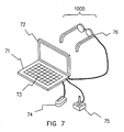
- a different aspect of the embodiments utilizes a plug in accessory data processor (Figure 7, (71)) with display (72) and data input device or devices such as a keyboard (73), mouse (74), or joystick (75).
- Figure 7 show the plug in unit (71) which plugs (76) into the logarithmic light amplifier (1000) to provide additional data processing ability as well as expanded data input and data display capability.
- One aspect of the different embodiments is the presence of a feedback loop using some of the reflected light from the scanning laser itself.
- One aspect of the feedback loop is to use regions of different reflectivity on the surface of the retinal implant which allow the location, or relative location, of the scanning laser light beam to be determined.
- a scanning laser feedback is provided in the different embodiments of the invention.
- An imaging ( Figure 9a) of the retinal implant from the reflected (92) incoming scanning laser beam (91), see Figure 9a, (7), ( Figure 1 and Figure 2a, (7)), ( Figure 3a, (9,), (10)) reflected back from the retinal implant ( Figure 9, (8)) can be used to provide real-time feedback information, utilizing a second imager (93) viewing into the eye (5) and a data processor unit (94) tied into the scanning laser's scan control unit (95).
- Figure 9b utilizes multiple fiduciary reflective or light absorptive points (96) and/or lines (97) on the retinal implant (8) such that the frequency and signal pattern, more generally, (98), (99), (100) of the high reflectivity from these reflective, or absorptive lines/point for a given rate of scanning by the scanning laser (7) can be used to correct the scanning direction from the different frequency patterns, some indicating correct scanning, others indicating an incorrect scanning.
Landscapes
- Health & Medical Sciences (AREA)
- Life Sciences & Earth Sciences (AREA)
- Public Health (AREA)
- Biomedical Technology (AREA)
- Veterinary Medicine (AREA)
- Engineering & Computer Science (AREA)
- Ophthalmology & Optometry (AREA)
- Animal Behavior & Ethology (AREA)
- General Health & Medical Sciences (AREA)
- Vascular Medicine (AREA)
- Heart & Thoracic Surgery (AREA)
- Nuclear Medicine, Radiotherapy & Molecular Imaging (AREA)
- Radiology & Medical Imaging (AREA)
- Prostheses (AREA)
- Eye Examination Apparatus (AREA)
Priority Applications (1)
| Application Number | Priority Date | Filing Date | Title |
|---|---|---|---|
| EP06026157A EP1864690A3 (en) | 1999-03-24 | 2000-03-03 | Logarithmic light intensifier for use with photoreceptorbased implanted retinal prosthetics and those prosthetics |
Applications Claiming Priority (3)
| Application Number | Priority Date | Filing Date | Title |
|---|---|---|---|
| US12587499P | 1999-03-24 | 1999-03-24 | |
| US125875P | 1999-03-24 | ||
| PCT/US2000/005753 WO2000056244A2 (en) | 1999-03-24 | 2000-03-03 | Logarithmic light intensifier for use with photoreceptor-based implanted retinal prosthetics and those prosthetics |
Related Child Applications (1)
| Application Number | Title | Priority Date | Filing Date |
|---|---|---|---|
| EP06026157A Division EP1864690A3 (en) | 1999-03-24 | 2000-03-03 | Logarithmic light intensifier for use with photoreceptorbased implanted retinal prosthetics and those prosthetics |
Publications (3)
| Publication Number | Publication Date |
|---|---|
| EP1194083A2 EP1194083A2 (en) | 2002-04-10 |
| EP1194083A4 EP1194083A4 (en) | 2005-02-02 |
| EP1194083B1 true EP1194083B1 (en) | 2007-05-02 |
Family
ID=34421214
Family Applications (1)
| Application Number | Title | Priority Date | Filing Date |
|---|---|---|---|
| EP00917743A Expired - Lifetime EP1194083B1 (en) | 1999-03-24 | 2000-03-03 | Logarithmic light intensifier for use with photoreceptor-based implanted retinal prosthetics and those prosthetics |
Country Status (7)
| Country | Link |
|---|---|
| US (4) | US6507758B1 (enExample) |
| EP (1) | EP1194083B1 (enExample) |
| JP (1) | JP4384363B2 (enExample) |
| AT (1) | ATE361041T1 (enExample) |
| AU (1) | AU780183B2 (enExample) |
| DE (1) | DE60034678T2 (enExample) |
| WO (1) | WO2000056244A2 (enExample) |
Families Citing this family (79)
| Publication number | Priority date | Publication date | Assignee | Title |
|---|---|---|---|---|
| ATE430596T1 (de) * | 1999-03-24 | 2009-05-15 | Second Sight Medical Prod Inc | Retinale farbprothese zur wiederherstellung des farbsehens |
| US6507758B1 (en) * | 1999-03-24 | 2003-01-14 | Second Sight, Llc | Logarithmic light intensifier for use with photoreceptor-based implanted retinal prosthetics and those prosthetics |
| US7103416B2 (en) * | 2001-01-16 | 2006-09-05 | Second Sight Medical Products, Inc. | Visual prosthesis including enhanced receiving and stimulating portion |
| DE60224677T2 (de) * | 2001-08-17 | 2009-01-08 | Advanced Bionics Corp., Sylmar | Allmähliche rekrutierung von erregbarem muskel/nerven-gewebe unter verwendung elektrischer stimulationsparameter mit hoher rate |
| WO2003061537A1 (en) * | 2002-01-17 | 2003-07-31 | Masachusetts Eye And Ear Infirmary | Minimally invasive retinal prosthesis |
| US7127301B1 (en) | 2003-04-28 | 2006-10-24 | Sandia Corporation | Flexible retinal electrode array |
| US8260428B2 (en) * | 2003-05-01 | 2012-09-04 | California Institute Of Technology | Method and system for training a visual prosthesis |
| US7321796B2 (en) * | 2003-05-01 | 2008-01-22 | California Institute Of Technology | Method and system for training a visual prosthesis |
| DE10329615A1 (de) * | 2003-06-23 | 2005-03-03 | Eberhard-Karls-Universität Tübingen Universitätsklinikum | Aktives Retina-Implantat mit einer Vielzahl von Bildelementen |
| US7311723B2 (en) * | 2003-07-11 | 2007-12-25 | University Of Washington | Scanning laser device and methods of use |
| US20050090875A1 (en) * | 2003-09-10 | 2005-04-28 | Palanker Daniel V. | Optical projection and tracking system for retinal prosthesis |
| GB2415631A (en) * | 2004-07-03 | 2006-01-04 | Martin Lister | Artificial eye with light sensitive LDRs |
| JP4310247B2 (ja) * | 2004-07-23 | 2009-08-05 | 株式会社ニデック | 視覚再生補助装置 |
| US8103352B2 (en) | 2004-12-03 | 2012-01-24 | Second Sight Medical Products, Inc. | Mimicking neural coding in retinal ganglion cells with short pulse electrical stimulation |
| US7571004B2 (en) | 2005-01-26 | 2009-08-04 | Second Sight Medical Products, Inc. | Neural stimulation for increased persistence |
| EP1858586B1 (en) * | 2005-02-16 | 2016-05-11 | Second Sight Medical Products, Inc. | Fitting of brightness in a visual prosthesis |
| DE102005032989A1 (de) * | 2005-07-14 | 2007-01-25 | Imi Intelligent Medical Implants Ag | Extraokulares Epiretinal-Implantat |
| WO2007035617A1 (en) * | 2005-09-16 | 2007-03-29 | Second Sight Medical Products, Inc. | Neural stimulation for increased contrast |
| US8709078B1 (en) * | 2011-08-03 | 2014-04-29 | Lockheed Martin Corporation | Ocular implant with substantially constant retinal spacing for transmission of nerve-stimulation light |
| US7877866B1 (en) * | 2005-10-26 | 2011-02-01 | Second Sight Medical Products, Inc. | Flexible circuit electrode array and method of manufacturing the same |
| WO2007127444A2 (en) * | 2006-04-28 | 2007-11-08 | Second Sight Medical Products, Inc. | Visual prosthesis fitting |
| WO2007149291A2 (en) * | 2006-06-16 | 2007-12-27 | Second Sight Medical Products, Inc. | A method for electrical stimulation of human retina using pulse trains |
| US8457754B2 (en) * | 2006-06-16 | 2013-06-04 | Second Sight Medical Products, Inc. | Apparatus and method for electrical stimulation of human neurons |
| US8311634B2 (en) * | 2006-06-16 | 2012-11-13 | Second Sight Medical Products Inc. | Apparatus and method for electrical stimulation of human retina |
| GB0612242D0 (en) * | 2006-06-21 | 2006-08-02 | Imp Innovations Ltd | Retinal prosthetic devices |
| EP2208367B1 (en) | 2007-10-12 | 2017-09-27 | Earlens Corporation | Multifunction system and method for integrated hearing and communiction with noise cancellation and feedback management |
| US9254385B2 (en) * | 2008-05-14 | 2016-02-09 | Second Sight Medical Products, Inc. | Visual prosthesis for phosphene shape control |
| DK2301261T3 (en) | 2008-06-17 | 2019-04-23 | Earlens Corp | Optical electromechanical hearing aids with separate power supply and signal components |
| US8700166B2 (en) * | 2008-08-07 | 2014-04-15 | Massachusetts Institute Of Technology | Coding for visual prostheses |
| WO2010033932A1 (en) | 2008-09-22 | 2010-03-25 | Earlens Corporation | Transducer devices and methods for hearing |
| US8428740B2 (en) | 2010-08-06 | 2013-04-23 | Nano-Retina, Inc. | Retinal prosthesis techniques |
| US8150526B2 (en) * | 2009-02-09 | 2012-04-03 | Nano-Retina, Inc. | Retinal prosthesis |
| US8718784B2 (en) * | 2010-01-14 | 2014-05-06 | Nano-Retina, Inc. | Penetrating electrodes for retinal stimulation |
| US8442641B2 (en) * | 2010-08-06 | 2013-05-14 | Nano-Retina, Inc. | Retinal prosthesis techniques |
| US8706243B2 (en) | 2009-02-09 | 2014-04-22 | Rainbow Medical Ltd. | Retinal prosthesis techniques |
| US9544700B2 (en) | 2009-06-15 | 2017-01-10 | Earlens Corporation | Optically coupled active ossicular replacement prosthesis |
| CN102598713A (zh) | 2009-06-18 | 2012-07-18 | 音束有限责任公司 | 用于听力系统的耳膜可植入装置及方法 |
| JP2012530552A (ja) * | 2009-06-18 | 2012-12-06 | サウンドビーム エルエルシー | 光学的に連結された蝸牛インプラントシステムおよび方法 |
| DK2446646T3 (en) | 2009-06-22 | 2019-02-04 | Earlens Corp | Hearing aid for coupling to the round window |
| WO2010151636A2 (en) | 2009-06-24 | 2010-12-29 | SoundBeam LLC | Optical cochlear stimulation devices and methods |
| WO2012088187A2 (en) | 2010-12-20 | 2012-06-28 | SoundBeam LLC | Anatomically customized ear canal hearing apparatus |
| US8571669B2 (en) | 2011-02-24 | 2013-10-29 | Nano-Retina, Inc. | Retinal prosthesis with efficient processing circuits |
| FR2975251B1 (fr) * | 2011-05-12 | 2015-12-04 | Univ Pierre Et Marie Curie Paris 6 | Procede et dispositif de commande d'un dispositif d'aide a la vision |
| US8715345B2 (en) * | 2011-05-23 | 2014-05-06 | California Institute Of Technology | Accommodating intraocular lens |
| AU2012259464B2 (en) * | 2011-05-23 | 2017-01-05 | California Institute Of Technology | Accommodating intraocular lens |
| CN102283742B (zh) * | 2011-08-15 | 2013-09-11 | 重庆大学 | 一种光刺激视网膜假体修复装置 |
| US10376301B2 (en) * | 2011-09-28 | 2019-08-13 | Covidien Lp | Logarithmic amplifier, electrosurgical generator including same, and method of controlling electrosurgical generator using same |
| EP2773423B1 (en) | 2011-11-04 | 2024-01-10 | Nevro Corporation | Medical device communication and charding assemblies for use with implantable signal generators |
| US9720477B2 (en) | 2012-11-21 | 2017-08-01 | Nano-Retina, Inc. | Weak power supply operation and control |
| US10121533B2 (en) | 2012-11-21 | 2018-11-06 | Nano-Retina, Inc. | Techniques for data retention in memory cells during power interruption |
| US9959674B2 (en) * | 2013-02-26 | 2018-05-01 | Qualcomm Incorporated | Directional and X-ray view techniques for navigation using a mobile device |
| US9370417B2 (en) | 2013-03-14 | 2016-06-21 | Nano-Retina, Inc. | Foveated retinal prosthesis |
| US9474902B2 (en) | 2013-12-31 | 2016-10-25 | Nano Retina Ltd. | Wearable apparatus for delivery of power to a retinal prosthesis |
| US9331791B2 (en) | 2014-01-21 | 2016-05-03 | Nano Retina Ltd. | Transfer of power and data |
| US10034103B2 (en) | 2014-03-18 | 2018-07-24 | Earlens Corporation | High fidelity and reduced feedback contact hearing apparatus and methods |
| DK3169396T3 (da) | 2014-07-14 | 2021-06-28 | Earlens Corp | Glidende forspænding og peak-begrænsning for optiske høreapparater |
| US9924276B2 (en) | 2014-11-26 | 2018-03-20 | Earlens Corporation | Adjustable venting for hearing instruments |
| TWI569817B (zh) * | 2015-07-08 | 2017-02-11 | 國立交通大學 | 人工視網膜系統、眼外光學裝置及眼內植入晶片 |
| EP3355801B1 (en) | 2015-10-02 | 2021-05-19 | Earlens Corporation | Drug delivery customized ear canal apparatus |
| US11350226B2 (en) | 2015-12-30 | 2022-05-31 | Earlens Corporation | Charging protocol for rechargeable hearing systems |
| US10492010B2 (en) | 2015-12-30 | 2019-11-26 | Earlens Corporations | Damping in contact hearing systems |
| US10306381B2 (en) | 2015-12-30 | 2019-05-28 | Earlens Corporation | Charging protocol for rechargable hearing systems |
| CN110114041B (zh) | 2016-06-23 | 2022-02-25 | 弗兰克·H·贝姆 | 用于融合骶髂关节的微创性外科手术系统 |
| WO2018048794A1 (en) | 2016-09-09 | 2018-03-15 | Earlens Corporation | Contact hearing systems, apparatus and methods |
| US11097105B2 (en) * | 2016-09-30 | 2021-08-24 | Shenzhen Sibionics Technology Co., Ltd. | Pulse current generation circuit for neural stimulation, charge compensation circuit and method, and implantable electrical retina stimulator |
| WO2018093733A1 (en) | 2016-11-15 | 2018-05-24 | Earlens Corporation | Improved impression procedure |
| US11638833B2 (en) | 2017-08-02 | 2023-05-02 | Multi Radiance Medical | Reducing light polution in photobiomodulation therapy of a patients eye |
| MX391427B (es) | 2017-08-02 | 2025-03-21 | Multi Radiance Medical | Sistema y metodo para dirigir luz al ojo de un paciente. |
| WO2019173470A1 (en) | 2018-03-07 | 2019-09-12 | Earlens Corporation | Contact hearing device and retention structure materials |
| WO2019199680A1 (en) | 2018-04-09 | 2019-10-17 | Earlens Corporation | Dynamic filter |
| EP3781257A4 (en) | 2018-05-01 | 2022-01-26 | Nevro Corp. | A 2.4 ghz radio antenna for implanted medical devices, and associated systems and methods |
| WO2020192943A1 (en) * | 2019-03-28 | 2020-10-01 | Pixium Vision Sa | Method and device for projecting a pattern of interest on a modified retinal area of a human eye |
| US20230355973A1 (en) * | 2020-09-24 | 2023-11-09 | University Of Southern California | System and method for restoring color perception to the blind |
| US20230337909A1 (en) * | 2020-09-29 | 2023-10-26 | Era Ophthalmica S.R.L. | Device for retinal neuromodulation therapy and extrafoveal reading in subjects affected by visual impairment |
| CN112717282B (zh) * | 2021-01-14 | 2023-01-10 | 重庆翰恒医疗科技有限公司 | 一种光诊疗装置及全自动光诊疗系统 |
| CN113258130B (zh) * | 2021-04-27 | 2023-01-03 | 燕山大学 | 非晶卤化物固体电解质及制备和在全固态电池中的应用 |
| KR102564879B1 (ko) * | 2021-06-02 | 2023-08-07 | 아주대학교산학협력단 | 2상 자극 시간 조절 방식의 인공망막 장치 및 그의 구동 방법 |
| US12295831B2 (en) | 2023-10-23 | 2025-05-13 | California Institute Of Technology | Liquid accommodating intraocular lens with an asymmetric chamber |
| CN119570731B (zh) * | 2024-12-10 | 2025-07-22 | 天津大学 | 一种在体外重建眼脑视觉通路模型的方法 |
Family Cites Families (22)
| Publication number | Priority date | Publication date | Assignee | Title |
|---|---|---|---|---|
| US3449768A (en) * | 1966-12-27 | 1969-06-17 | James H Doyle | Artificial sense organ |
| GB1286316A (en) * | 1969-11-13 | 1972-08-23 | Hermann Mengeler | Method and apparatus for transmitting optical impressions upon the visual regions of the human cerebral cortex |
| DE2948266A1 (de) * | 1979-11-30 | 1981-06-19 | geb. Lehrmund Margot 8000 München Stover | Sehgeraet |
| US4611596A (en) * | 1980-10-14 | 1986-09-16 | Purdue Research Foundation | Sensory prostheses |
| US4628933A (en) | 1985-07-23 | 1986-12-16 | Michelson Robin P | Method and apparatus for visual prosthesis |
| US4677989A (en) * | 1986-02-06 | 1987-07-07 | Eic Laboratories, Inc. | Iridium oxide coated electrodes for neural stimulation |
| US5016633A (en) | 1989-08-08 | 1991-05-21 | Chow Alan Y | Artificial retina device |
| US5109844A (en) * | 1990-10-11 | 1992-05-05 | Duke University | Retinal microstimulation |
| US5369415A (en) | 1992-06-29 | 1994-11-29 | Motorola, Inc. | Direct retinal scan display with planar imager |
| US5467104A (en) | 1992-10-22 | 1995-11-14 | Board Of Regents Of The University Of Washington | Virtual retinal display |
| US5556423A (en) | 1993-05-03 | 1996-09-17 | Alan Y. Chow | Independent photoelectric artificial retina device and method of using same |
| US5397350A (en) | 1993-05-03 | 1995-03-14 | Chow; Alan Y. | Independent photoelectric artificial retina device and method of using same |
| US5895415A (en) | 1995-06-06 | 1999-04-20 | Optobionics Corporation | Multi-phasic microphotodiode retinal implant and adaptive imaging retinal stimulation system |
| AU709207B2 (en) | 1995-06-06 | 1999-08-26 | Optobionics Corporation | Multi-phasic microphotodiode retinal implant and adaptive imaging retinal stimulation system |
| US5957958A (en) | 1997-01-15 | 1999-09-28 | Advanced Bionics Corporation | Implantable electrode arrays |
| DE19707046A1 (de) * | 1997-02-21 | 1998-08-27 | Rolf Prof Dr Ing Eckmiller | Lernfähiger "Active Vision" Implant Encoder |
| US6458157B1 (en) * | 1997-08-04 | 2002-10-01 | Suaning Gregg Joergen | Retinal stimulator |
| US5935155A (en) | 1998-03-13 | 1999-08-10 | John Hopkins University, School Of Medicine | Visual prosthesis and method of using same |
| US5944747A (en) | 1998-03-13 | 1999-08-31 | Johns Hopkins University | Method for preferential outer retinal stimulation |
| US6397350B1 (en) * | 1999-02-19 | 2002-05-28 | International Business Machines Corporation | Method of providing direct data processing access using a queued direct input-output device |
| US6507758B1 (en) * | 1999-03-24 | 2003-01-14 | Second Sight, Llc | Logarithmic light intensifier for use with photoreceptor-based implanted retinal prosthetics and those prosthetics |
| US6389317B1 (en) * | 2000-03-31 | 2002-05-14 | Optobionics Corporation | Multi-phasic microphotodetector retinal implant with variable voltage and current capability |
-
2000
- 2000-02-29 US US09/515,383 patent/US6507758B1/en not_active Expired - Lifetime
- 2000-03-03 DE DE60034678T patent/DE60034678T2/de not_active Expired - Fee Related
- 2000-03-03 AT AT00917743T patent/ATE361041T1/de not_active IP Right Cessation
- 2000-03-03 JP JP2000606153A patent/JP4384363B2/ja not_active Expired - Fee Related
- 2000-03-03 EP EP00917743A patent/EP1194083B1/en not_active Expired - Lifetime
- 2000-03-03 WO PCT/US2000/005753 patent/WO2000056244A2/en not_active Ceased
- 2000-03-03 AU AU38671/00A patent/AU780183B2/en not_active Ceased
-
2002
- 2002-11-26 US US10/304,815 patent/US7133724B2/en not_active Expired - Lifetime
-
2006
- 2006-09-14 US US11/522,001 patent/US7539544B2/en not_active Expired - Fee Related
-
2009
- 2009-04-16 US US12/425,236 patent/US8046078B2/en not_active Expired - Fee Related
Also Published As
| Publication number | Publication date |
|---|---|
| WO2000056244A2 (en) | 2000-09-28 |
| JP2002538936A (ja) | 2002-11-19 |
| US20090204212A1 (en) | 2009-08-13 |
| US6507758B1 (en) | 2003-01-14 |
| DE60034678T2 (de) | 2008-01-17 |
| AU780183B2 (en) | 2005-03-03 |
| DE60034678D1 (de) | 2007-06-14 |
| US7539544B2 (en) | 2009-05-26 |
| US7133724B2 (en) | 2006-11-07 |
| US20030181957A1 (en) | 2003-09-25 |
| WO2000056244A3 (en) | 2002-01-24 |
| EP1194083A4 (en) | 2005-02-02 |
| EP1194083A2 (en) | 2002-04-10 |
| AU3867100A (en) | 2000-10-09 |
| ATE361041T1 (de) | 2007-05-15 |
| JP4384363B2 (ja) | 2009-12-16 |
| US20070016294A1 (en) | 2007-01-18 |
| US8046078B2 (en) | 2011-10-25 |
Similar Documents
| Publication | Publication Date | Title |
|---|---|---|
| EP1194083B1 (en) | Logarithmic light intensifier for use with photoreceptor-based implanted retinal prosthetics and those prosthetics | |
| EP2393547B1 (en) | Retinal prosthesis | |
| US8956396B1 (en) | Eye-tracking visual prosthetic and method | |
| EP2012873B1 (en) | Active sub-retina implant | |
| EP1171188B1 (en) | Retinal color prosthesis for color sight restoration | |
| US8945197B1 (en) | Sight-restoring visual prosthetic and method using infrared nerve-stimulation light | |
| TWI569817B (zh) | 人工視網膜系統、眼外光學裝置及眼內植入晶片 | |
| AU2004273093A1 (en) | Optical projection and tracking system for retinal prosthesis | |
| EP1864690A2 (en) | Logarithmic light intensifier for use with photoreceptorbased implanted retinal prosthetics and those prosthetics | |
| JP7635502B2 (ja) | ヒトの眼の改変された網膜領域に関心のあるパターンを投射するための方法及び装置 | |
| AU2005200113A1 (en) | Logarithmic light intensifier for use with photoreceptor-based implanted retinal prosthetics and those prosthetics | |
| AU2008203817A1 (en) | Logarithmic light intensifier for use with photoreceptor-based implanted retinal prosthetics and those prosthetics |
Legal Events
| Date | Code | Title | Description |
|---|---|---|---|
| PUAI | Public reference made under article 153(3) epc to a published international application that has entered the european phase |
Free format text: ORIGINAL CODE: 0009012 |
|
| 17P | Request for examination filed |
Effective date: 20011022 |
|
| AK | Designated contracting states |
Kind code of ref document: A2 Designated state(s): AT BE CH CY DE DK ES FI FR GB GR IE IT LI LU MC NL PT SE |
|
| AX | Request for extension of the european patent |
Free format text: AL;LT;LV;MK;RO;SI |
|
| A4 | Supplementary search report drawn up and despatched |
Effective date: 20041222 |
|
| RIC1 | Information provided on ipc code assigned before grant |
Ipc: 7A 61F 2/14 A Ipc: 7A 61N 1/36 B |
|
| 17Q | First examination report despatched |
Effective date: 20050518 |
|
| RAP1 | Party data changed (applicant data changed or rights of an application transferred) |
Owner name: SECOND SIGHT MEDICAL PRODUCTS, INC. |
|
| GRAP | Despatch of communication of intention to grant a patent |
Free format text: ORIGINAL CODE: EPIDOSNIGR1 |
|
| GRAS | Grant fee paid |
Free format text: ORIGINAL CODE: EPIDOSNIGR3 |
|
| GRAA | (expected) grant |
Free format text: ORIGINAL CODE: 0009210 |
|
| AK | Designated contracting states |
Kind code of ref document: B1 Designated state(s): AT BE CH CY DE DK ES FI FR GB GR IE IT LI LU MC NL PT SE |
|
| PG25 | Lapsed in a contracting state [announced via postgrant information from national office to epo] |
Ref country code: FI Free format text: LAPSE BECAUSE OF FAILURE TO SUBMIT A TRANSLATION OF THE DESCRIPTION OR TO PAY THE FEE WITHIN THE PRESCRIBED TIME-LIMIT Effective date: 20070502 |
|
| REG | Reference to a national code |
Ref country code: GB Ref legal event code: FG4D |
|
| REG | Reference to a national code |
Ref country code: CH Ref legal event code: EP |
|
| REG | Reference to a national code |
Ref country code: IE Ref legal event code: FG4D |
|
| REF | Corresponds to: |
Ref document number: 60034678 Country of ref document: DE Date of ref document: 20070614 Kind code of ref document: P |
|
| PG25 | Lapsed in a contracting state [announced via postgrant information from national office to epo] |
Ref country code: SE Free format text: LAPSE BECAUSE OF FAILURE TO SUBMIT A TRANSLATION OF THE DESCRIPTION OR TO PAY THE FEE WITHIN THE PRESCRIBED TIME-LIMIT Effective date: 20070802 |
|
| PG25 | Lapsed in a contracting state [announced via postgrant information from national office to epo] |
Ref country code: ES Free format text: LAPSE BECAUSE OF FAILURE TO SUBMIT A TRANSLATION OF THE DESCRIPTION OR TO PAY THE FEE WITHIN THE PRESCRIBED TIME-LIMIT Effective date: 20070813 |
|
| ET | Fr: translation filed | ||
| NLV1 | Nl: lapsed or annulled due to failure to fulfill the requirements of art. 29p and 29m of the patents act | ||
| PG25 | Lapsed in a contracting state [announced via postgrant information from national office to epo] |
Ref country code: AT Free format text: LAPSE BECAUSE OF FAILURE TO SUBMIT A TRANSLATION OF THE DESCRIPTION OR TO PAY THE FEE WITHIN THE PRESCRIBED TIME-LIMIT Effective date: 20070502 |
|
| PG25 | Lapsed in a contracting state [announced via postgrant information from national office to epo] |
Ref country code: BE Free format text: LAPSE BECAUSE OF FAILURE TO SUBMIT A TRANSLATION OF THE DESCRIPTION OR TO PAY THE FEE WITHIN THE PRESCRIBED TIME-LIMIT Effective date: 20070502 |
|
| PG25 | Lapsed in a contracting state [announced via postgrant information from national office to epo] |
Ref country code: DK Free format text: LAPSE BECAUSE OF FAILURE TO SUBMIT A TRANSLATION OF THE DESCRIPTION OR TO PAY THE FEE WITHIN THE PRESCRIBED TIME-LIMIT Effective date: 20070502 Ref country code: PT Free format text: LAPSE BECAUSE OF FAILURE TO SUBMIT A TRANSLATION OF THE DESCRIPTION OR TO PAY THE FEE WITHIN THE PRESCRIBED TIME-LIMIT Effective date: 20071002 Ref country code: NL Free format text: LAPSE BECAUSE OF FAILURE TO SUBMIT A TRANSLATION OF THE DESCRIPTION OR TO PAY THE FEE WITHIN THE PRESCRIBED TIME-LIMIT Effective date: 20070502 |
|
| PLBE | No opposition filed within time limit |
Free format text: ORIGINAL CODE: 0009261 |
|
| STAA | Information on the status of an ep patent application or granted ep patent |
Free format text: STATUS: NO OPPOSITION FILED WITHIN TIME LIMIT |
|
| 26N | No opposition filed |
Effective date: 20080205 |
|
| PG25 | Lapsed in a contracting state [announced via postgrant information from national office to epo] |
Ref country code: GR Free format text: LAPSE BECAUSE OF FAILURE TO SUBMIT A TRANSLATION OF THE DESCRIPTION OR TO PAY THE FEE WITHIN THE PRESCRIBED TIME-LIMIT Effective date: 20070803 Ref country code: IT Free format text: LAPSE BECAUSE OF FAILURE TO SUBMIT A TRANSLATION OF THE DESCRIPTION OR TO PAY THE FEE WITHIN THE PRESCRIBED TIME-LIMIT Effective date: 20070502 |
|
| PG25 | Lapsed in a contracting state [announced via postgrant information from national office to epo] |
Ref country code: MC Free format text: LAPSE BECAUSE OF NON-PAYMENT OF DUE FEES Effective date: 20080331 |
|
| PG25 | Lapsed in a contracting state [announced via postgrant information from national office to epo] |
Ref country code: IE Free format text: LAPSE BECAUSE OF NON-PAYMENT OF DUE FEES Effective date: 20080303 |
|
| PGFP | Annual fee paid to national office [announced via postgrant information from national office to epo] |
Ref country code: GB Payment date: 20090220 Year of fee payment: 10 Ref country code: CH Payment date: 20090224 Year of fee payment: 10 |
|
| PG25 | Lapsed in a contracting state [announced via postgrant information from national office to epo] |
Ref country code: CY Free format text: LAPSE BECAUSE OF FAILURE TO SUBMIT A TRANSLATION OF THE DESCRIPTION OR TO PAY THE FEE WITHIN THE PRESCRIBED TIME-LIMIT Effective date: 20070502 |
|
| PGFP | Annual fee paid to national office [announced via postgrant information from national office to epo] |
Ref country code: DE Payment date: 20090225 Year of fee payment: 10 |
|
| PGFP | Annual fee paid to national office [announced via postgrant information from national office to epo] |
Ref country code: FR Payment date: 20090224 Year of fee payment: 10 |
|
| PG25 | Lapsed in a contracting state [announced via postgrant information from national office to epo] |
Ref country code: LU Free format text: LAPSE BECAUSE OF NON-PAYMENT OF DUE FEES Effective date: 20080303 |
|
| REG | Reference to a national code |
Ref country code: CH Ref legal event code: PL |
|
| GBPC | Gb: european patent ceased through non-payment of renewal fee |
Effective date: 20100303 |
|
| REG | Reference to a national code |
Ref country code: FR Ref legal event code: ST Effective date: 20101130 |
|
| PG25 | Lapsed in a contracting state [announced via postgrant information from national office to epo] |
Ref country code: FR Free format text: LAPSE BECAUSE OF NON-PAYMENT OF DUE FEES Effective date: 20100331 |
|
| PG25 | Lapsed in a contracting state [announced via postgrant information from national office to epo] |
Ref country code: LI Free format text: LAPSE BECAUSE OF NON-PAYMENT OF DUE FEES Effective date: 20100331 Ref country code: CH Free format text: LAPSE BECAUSE OF NON-PAYMENT OF DUE FEES Effective date: 20100331 Ref country code: DE Free format text: LAPSE BECAUSE OF NON-PAYMENT OF DUE FEES Effective date: 20101001 |
|
| PG25 | Lapsed in a contracting state [announced via postgrant information from national office to epo] |
Ref country code: GB Free format text: LAPSE BECAUSE OF NON-PAYMENT OF DUE FEES Effective date: 20100303 |