EP1193838B1 - Uberlastgeschützter Elektromotor, inbesondere Gleichstrom-Kommutatormotor - Google Patents
Uberlastgeschützter Elektromotor, inbesondere Gleichstrom-Kommutatormotor Download PDFInfo
- Publication number
- EP1193838B1 EP1193838B1 EP00118828A EP00118828A EP1193838B1 EP 1193838 B1 EP1193838 B1 EP 1193838B1 EP 00118828 A EP00118828 A EP 00118828A EP 00118828 A EP00118828 A EP 00118828A EP 1193838 B1 EP1193838 B1 EP 1193838B1
- Authority
- EP
- European Patent Office
- Prior art keywords
- electric motor
- earth
- switching element
- overload
- motor
- Prior art date
- Legal status (The legal status is an assumption and is not a legal conclusion. Google has not performed a legal analysis and makes no representation as to the accuracy of the status listed.)
- Expired - Lifetime
Links
- 238000013021 overheating Methods 0.000 claims description 12
- 230000007935 neutral effect Effects 0.000 claims description 3
- 238000004804 winding Methods 0.000 description 5
- 238000010438 heat treatment Methods 0.000 description 3
- 238000010586 diagram Methods 0.000 description 2
- 230000001629 suppression Effects 0.000 description 2
- OKTJSMMVPCPJKN-UHFFFAOYSA-N Carbon Chemical compound [C] OKTJSMMVPCPJKN-UHFFFAOYSA-N 0.000 description 1
- 239000000654 additive Substances 0.000 description 1
- 230000000903 blocking effect Effects 0.000 description 1
- 229910052799 carbon Inorganic materials 0.000 description 1
- 238000010276 construction Methods 0.000 description 1
- 230000002950 deficient Effects 0.000 description 1
- 238000005516 engineering process Methods 0.000 description 1
- 231100001261 hazardous Toxicity 0.000 description 1
- 238000009434 installation Methods 0.000 description 1
- 238000004519 manufacturing process Methods 0.000 description 1
- 230000001681 protective effect Effects 0.000 description 1
- 230000005855 radiation Effects 0.000 description 1
- 238000010792 warming Methods 0.000 description 1
Images
Classifications
-
- H—ELECTRICITY
- H02—GENERATION; CONVERSION OR DISTRIBUTION OF ELECTRIC POWER
- H02K—DYNAMO-ELECTRIC MACHINES
- H02K23/00—DC commutator motors or generators having mechanical commutator; Universal AC/DC commutator motors
- H02K23/66—Structural association with auxiliary electric devices influencing the characteristic of, or controlling, the machine, e.g. with impedances or switches
-
- H—ELECTRICITY
- H02—GENERATION; CONVERSION OR DISTRIBUTION OF ELECTRIC POWER
- H02K—DYNAMO-ELECTRIC MACHINES
- H02K11/00—Structural association of dynamo-electric machines with electric components or with devices for shielding, monitoring or protection
- H02K11/20—Structural association of dynamo-electric machines with electric components or with devices for shielding, monitoring or protection for measuring, monitoring, testing, protecting or switching
- H02K11/25—Devices for sensing temperature, or actuated thereby
-
- H—ELECTRICITY
- H01—ELECTRIC ELEMENTS
- H01H—ELECTRIC SWITCHES; RELAYS; SELECTORS; EMERGENCY PROTECTIVE DEVICES
- H01H85/00—Protective devices in which the current flows through a part of fusible material and this current is interrupted by displacement of the fusible material when this current becomes excessive
- H01H85/02—Details
- H01H85/46—Circuit arrangements not adapted to a particular application of the protective device
-
- H—ELECTRICITY
- H02—GENERATION; CONVERSION OR DISTRIBUTION OF ELECTRIC POWER
- H02H—EMERGENCY PROTECTIVE CIRCUIT ARRANGEMENTS
- H02H7/00—Emergency protective circuit arrangements specially adapted for specific types of electric machines or apparatus or for sectionalised protection of cable or line systems, and effecting automatic switching in the event of an undesired change from normal working conditions
- H02H7/08—Emergency protective circuit arrangements specially adapted for specific types of electric machines or apparatus or for sectionalised protection of cable or line systems, and effecting automatic switching in the event of an undesired change from normal working conditions for dynamo-electric motors
- H02H7/0811—Emergency protective circuit arrangements specially adapted for specific types of electric machines or apparatus or for sectionalised protection of cable or line systems, and effecting automatic switching in the event of an undesired change from normal working conditions for dynamo-electric motors for DC motors
Definitions
- the invention relates to an overload protected Electric motor, in particular DC commutator motor, according to Claim 1; such an engine is particularly a mass-produced product for use as a servo or servomotor in an automobile, e.g. as a fan drive motor according to the DE 197 21 316 C1 and DE 34 34 429 C2, respectively.
- Such motors are usually secured by a main fuse secured and speak for the total load due to their design one to be monitored, including containing the electric motor Circuit with blocked or stiff Electric motor not fast enough or not at all, so that the defective engine is excessive, possibly up to to fire damage, can overheat.
- a heat sensitive Switch close to the winding to be protected bring and if a specifiable winding temperature is exceeded to short-circuit a winding part with the switch, so the main switch turns off the engine Disconnects the voltage source at least until the specifiable one Again falls below the winding temperature; Bimetallic switch as protective elements against engine overheating more generally known.
- US-A-4 177 396 is overheating protection for one Commutator motor known so that in the event of overheating Bimetal element held on the motor side due to its deformation an interruption in the power supply to the brushes of the commutator motor causes.
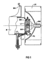
- 1 shows in known from DE 197 21 316 C1 and 2; 3 each show the commutator side in an additional manner according to the invention End of a commutator motor provided as an electric motor M, whose motor housing via a motor bracket MH, can be fixed in a holder, especially a blower housing and on the front end of the rotor shaft RW a fan wheel LR is held.
- a commutator motor provided as an electric motor M, whose motor housing via a motor bracket MH, can be fixed in a holder, especially a blower housing and on the front end of the rotor shaft RW a fan wheel LR is held.
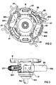
- Hammer brush holder HB1; HB2 in a commutator side Bearing bracket LB are pivotally mounted.
- radio interference suppression chokes DR1; DR2 arranged: these are each with one end Connection A1 or A3 via strands with the commutator grinding carbon brushes B1 and B2 and with their other End connection A2 or A4 with external power supply lines L1; L2 connected in series.
- an intermediate terminal board KL is provided with which the external power supply lines L1; L2 strain relieved on the LB bracket can be fixed and one of the two power cables, especially when used in a motor vehicle, with the negative pole N of the vehicle battery P; N.
- the negative pole N of the battery is in turn in its Installation proximity connected to mass MP of the vehicle
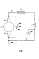
- an electric motor M is the one described above Type according to the construction example in FIG. 2; 3 or according to the circuit diagram in FIG 4 to ensure one in each Case of safe and quick response in the course of Connection between a vehicle battery P; N and the Commutator K grinding brushes B1; B2 arranged main fuse SI with a bimetallic switching element BS as a short-circuit release for the otherwise not appealing Main fuse provided in case of excessive heating.
- the bimetal switching element BS is advantageously in the Heat radiation area of the commutator K or the one grinding it Brushes B1; B2 and in manufacturing technology particularly simply with a fastening of his one End BS1 on a stator part used as ground MP, in particular a bracket LB, the electric motor M and with his other free end BS2 from a non-contact neutral position in a contact position for electrical connection A1 one of a brush holder B2, in particular a hammer brush holder HB1, the suppressed choke DR1 with of the supply line L2 isolated from the ground MP.
- a quick and safe overheating or Fire protection for one in a circuit with other consumers only protected by a main fuse SI Electric motor M can by simple means by an Overload case provoked by the additional warming full short circuit can be achieved; structurally particularly simple The way closes in a motor vehicle commutator motor a bimetallic switching element BS in the area of the brushes B1; B2 connected to the one battery pole N and ground MP Supply line L1 with the one connected to the other battery pole P. to the ground MP otherwise isolated supply line L2 short.
Landscapes
- Engineering & Computer Science (AREA)
- Power Engineering (AREA)
- Microelectronics & Electronic Packaging (AREA)
- Fuses (AREA)
Description
- FIG 1
- in einem axialen Teilschnitt das kommutatorseitige Ende eines bekannten Kommutatormotors zum Antrieb des Schaufelrades eines Kraftfahrzeug-Innenlüfters;
- FIG 2,3
- in axialer bzw. radialer Draufsicht den kommutatorseitigen Ausschnitt eines Kommutatormotors gemäß FIG 1 zusätzlich mit nachträglich einbaubarer Kurzschluss-Auslösung bei Gefahr einer Motorüberhitzung;
- FIG 4
- das Schaltbild zu der erfindungsgemäß provozierten Kurzschluss-Auslösung einer Haupt-Sicherung bei Gefahr einer Motor-Überhitzung.
Claims (5)
- Überlastgeschützter Elektromotor, insbesondere Gleichstrom-Kommutatormotor,mit einer dem Elektromotor (M) und weiteren Verbrauchern seines Stromkreises zum Schutz in einem Überlastfall zugeordneten, bei Ansprechen die Speisespannung (P;N) abtrennenden, Haupt-Sicherung (SI);mit einem aufgrund einer definierten Motorüberhitzung einen gewollten satten Kurzschluss des Elektromotors (M) bewirkenden und dadurch die Haupt-Sicherung (SI) zum Ansprechen bringenden Schaltelement;mit einem Elektromotor (M) in Form eines Kommutatormotors mit einer Stromzuführung zu zumindest zwei einen Kommutator (K) beschleifenden Bürsten (B1;B2), von denen eine erste Bürste (B1) über eine auch an Masse (MP) des Elektromotors (M) angeschlossene Zuleitung (L1) und eine zweite Bürste (B) über eine zu der Masse (MP) isolierte Zuleitung (L2) aus der Speisespannung (P;N) gespeist ist;mit einem Schaltelement in Form eines mit der Masse (MP) verbundenen und bei Erreichen der definierten Motorüberhitzung durch Schaltbewegung die Masse (MP) mit einem freien Anschluss (A1) der zur Masse (MP) isolierten Zuleitung (L2) kontaktierenden Bimetall-Schaltelementes (BS) oder dergleichen.
- Überlastgeschützter Elektromotor nach Anspruch 1mit einem Schaltelement in Form eines mit seinem einen Ende (BS1) an der Masse (MP) befestigten, elektrisch leitfähigen Bimetall-Schaltelement (BS), dessen anderes freies Ende (BS2) bei Erreichen der definierten Überhitzung aus einer Neutral-Stellung in eine Kurzschluss-Stellung mit dem freien Anschluss (A2) der zu der Masse (MP) isolierten Zuleitung (L2) verstellt ist.
- Überlastgeschützter Elektromotor nach Anspruch 2mit einer Befestigung des einen Endes (BS1) des Bimetall-Schaltelementes (BS) an einem als Masse (MP) benutzten Statorteil, insbesondere einem Lagerbügel (LB), des Elektromotors (M);mit einer Kurzschluss-Kontaktstellung des anderen freien Endes (BS2) des Bimetall-Schaltelementes (BS) zu dem freien Anschluss (A1) einer von einem Bürstenhalter (B2), insbesondere einem Hammerbürstenhalter, aufgenommenen Entstördrossel (DR1) mit der zu der Masse (MP) isolierten Zuleitung (L2).
- Überlastgeschützter Elektromotor nach Anspruch 2 und/oder 3mit einer Anordnung des Bimetall-Schaltelementes (BS) im Wärmestrahlungsbereich des Kommutators (K) des Elektromotors (M).
- Überlastgeschützter Elektromotor nach zumindest einem der Ansprüche 1-4mit einer Anwendung zum Antrieb eines Kraftfahrzeug-Lüfters, insbesondere eines Innenraumlüfters.
Priority Applications (3)
| Application Number | Priority Date | Filing Date | Title |
|---|---|---|---|
| ES00118828T ES2201979T3 (es) | 2000-08-31 | 2000-08-31 | Motor electrico protegido contra sobrecarga, especialmente motor de conmutador de corriente continua. |
| DE50002749T DE50002749D1 (de) | 2000-08-31 | 2000-08-31 | Uberlastgeschützter Elektromotor, inbesondere Gleichstrom-Kommutatormotor |
| EP00118828A EP1193838B1 (de) | 2000-08-31 | 2000-08-31 | Uberlastgeschützter Elektromotor, inbesondere Gleichstrom-Kommutatormotor |
Applications Claiming Priority (1)
| Application Number | Priority Date | Filing Date | Title |
|---|---|---|---|
| EP00118828A EP1193838B1 (de) | 2000-08-31 | 2000-08-31 | Uberlastgeschützter Elektromotor, inbesondere Gleichstrom-Kommutatormotor |
Publications (2)
| Publication Number | Publication Date |
|---|---|
| EP1193838A1 EP1193838A1 (de) | 2002-04-03 |
| EP1193838B1 true EP1193838B1 (de) | 2003-07-02 |
Family
ID=8169705
Family Applications (1)
| Application Number | Title | Priority Date | Filing Date |
|---|---|---|---|
| EP00118828A Expired - Lifetime EP1193838B1 (de) | 2000-08-31 | 2000-08-31 | Uberlastgeschützter Elektromotor, inbesondere Gleichstrom-Kommutatormotor |
Country Status (3)
| Country | Link |
|---|---|
| EP (1) | EP1193838B1 (de) |
| DE (1) | DE50002749D1 (de) |
| ES (1) | ES2201979T3 (de) |
Cited By (1)
| Publication number | Priority date | Publication date | Assignee | Title |
|---|---|---|---|---|
| DE102016106661A1 (de) | 2016-04-12 | 2017-10-12 | Dr. Ing. H.C. F. Porsche Aktiengesellschaft | Elektrische Schaltung für ein elektrisch angetriebenes Fahrzeug |
Families Citing this family (4)
| Publication number | Priority date | Publication date | Assignee | Title |
|---|---|---|---|---|
| DE102004010959A1 (de) * | 2003-03-10 | 2004-09-23 | Behr Gmbh & Co. Kg | Anordnung zum Schutz vor Überlast eines Elektromotors |
| DE102010030870A1 (de) * | 2010-07-02 | 2012-01-05 | Robert Bosch Gmbh | Elektromotor |
| CN102651545B (zh) * | 2011-02-25 | 2014-08-06 | 海洋王照明科技股份有限公司 | 一种直流电机堵转保护电路 |
| CN120165504B (zh) * | 2025-05-19 | 2025-08-05 | 浙江中贝能源科技有限公司 | 基于智能熔断器的电网侧故障处理方法及相关装置 |
Family Cites Families (5)
| Publication number | Priority date | Publication date | Assignee | Title |
|---|---|---|---|---|
| FR2373905A1 (fr) * | 1976-12-10 | 1978-07-07 | Johnson Electric Ind Mfg | Perfectionnement aux moteurs electriques |
| JPS61214723A (ja) * | 1985-03-20 | 1986-09-24 | 住友電気工業株式会社 | モ−タ過熱保護装置 |
| JPH03173314A (ja) * | 1989-11-30 | 1991-07-26 | Fuji Electric Co Ltd | 回転電機の過熱防止装置 |
| FR2730357A1 (fr) * | 1995-02-08 | 1996-08-09 | Alsthom Gec | Systeme permettant de deconnecter electriquement de son alimentation un appareillage electrique a isolation par un dielectrique liquide |
| DE19741828A1 (de) * | 1997-09-23 | 1999-03-25 | Pudenz Wilhelm Gmbh | Elektrischer Sicherheitsschalter für Kraftfahrzeuge |
-
2000
- 2000-08-31 EP EP00118828A patent/EP1193838B1/de not_active Expired - Lifetime
- 2000-08-31 DE DE50002749T patent/DE50002749D1/de not_active Expired - Lifetime
- 2000-08-31 ES ES00118828T patent/ES2201979T3/es not_active Expired - Lifetime
Cited By (1)
| Publication number | Priority date | Publication date | Assignee | Title |
|---|---|---|---|---|
| DE102016106661A1 (de) | 2016-04-12 | 2017-10-12 | Dr. Ing. H.C. F. Porsche Aktiengesellschaft | Elektrische Schaltung für ein elektrisch angetriebenes Fahrzeug |
Also Published As
| Publication number | Publication date |
|---|---|
| DE50002749D1 (de) | 2003-08-07 |
| ES2201979T3 (es) | 2004-04-01 |
| EP1193838A1 (de) | 2002-04-03 |
Similar Documents
| Publication | Publication Date | Title |
|---|---|---|
| DE102016106557A1 (de) | Hand-Werkzeugmaschine mit einem Antriebsmotor | |
| EP3443628A1 (de) | Hand-werkzeugmaschine mit einem trennschalter | |
| DE3837943C2 (de) | ||
| EP1876626A2 (de) | Schutzschalter-Kurzschließer-Kombination | |
| DE1817655A1 (de) | Schutzschaltung fuer einen buerstenlosen Generator mit Haupt- und Hilfserregermaschine und rotierender Gleichrichteranordnung | |
| WO2001050577A1 (de) | Elektrische sicherung für drehstromgeneratoren mit gleichrichter | |
| DE2724269A1 (de) | Ueberlastungssichere schaltung zur leistungsabstufung elektrischer geblaeseantriebe | |
| EP1193838A1 (de) | Uberlastgeschützter Elektromotor, inbesondere Gleichstrom-Kommutatormotor | |
| EP0867065B1 (de) | Reihenschlussmotor mit elektrischer bremse | |
| DE102016226228B4 (de) | Elektrorotationsmaschine mit integrierter Steuereinheit | |
| EP1498997B1 (de) | Schiffs-Energieversorgungs-und-verteilungsanlage | |
| DE602005005217T2 (de) | Versorgungsschaltung für eine elektromotorbürste insbesondere eines kraftfahrzeug-anlassers | |
| DE828881C (de) | Trennschutzschaltung mit UEberstromschutz | |
| DE69406902T2 (de) | Überstromschutzschaltung | |
| DE1049486B (de) | Schutzvorrichtung fuer stromkreise und elektrische geraete | |
| EP4258310A1 (de) | Gehäusemodul, isolierstoffgehäuse und schutzschaltgerät | |
| DE60314945T2 (de) | Gesicherte Vorrichtung zur Erregung eines elektrischen Leistungsgenerators und zugehöriges Verfahren | |
| US1580810A (en) | Dynamo-electric machine | |
| US1677699A (en) | System of electrical distribution | |
| DE102015226207A1 (de) | Elektrische Maschine | |
| DE443852C (de) | Mit Selbsterregung versehene Dynamo fuer elektrische Lichtbogenschweissung | |
| JP2550214Y2 (ja) | 電源装置 | |
| SU796978A2 (ru) | Устройство дл защиты трехфазного электро-дВигАТЕл OT РАбОТы HA дВуХ фАзАХ и пЕРЕ-гРузОК | |
| DE3526176C2 (de) | ||
| AT228306B (de) | Schutzeinrichtung für ungeerdete Drehstrommotore |
Legal Events
| Date | Code | Title | Description |
|---|---|---|---|
| GRAG | Despatch of communication of intention to grant |
Free format text: ORIGINAL CODE: EPIDOS AGRA |
|
| GRAG | Despatch of communication of intention to grant |
Free format text: ORIGINAL CODE: EPIDOS AGRA |
|
| GRAH | Despatch of communication of intention to grant a patent |
Free format text: ORIGINAL CODE: EPIDOS IGRA |
|
| PUAI | Public reference made under article 153(3) epc to a published international application that has entered the european phase |
Free format text: ORIGINAL CODE: 0009012 |
|
| 17P | Request for examination filed |
Effective date: 20010419 |
|
| AK | Designated contracting states |
Kind code of ref document: A1 Designated state(s): AT BE CH CY DE DK ES FI FR GB GR IE IT LI LU MC NL PT SE Kind code of ref document: A1 Designated state(s): DE ES FR IT |
|
| AX | Request for extension of the european patent |
Free format text: AL;LT;LV;MK;RO;SI |
|
| GRAH | Despatch of communication of intention to grant a patent |
Free format text: ORIGINAL CODE: EPIDOS IGRA |
|
| AKX | Designation fees paid |
Free format text: DE ES FR IT |
|
| GRAA | (expected) grant |
Free format text: ORIGINAL CODE: 0009210 |
|
| AK | Designated contracting states |
Designated state(s): DE ES FR IT |
|
| REG | Reference to a national code |
Ref country code: IE Ref legal event code: FG4D Free format text: GERMAN |
|
| REF | Corresponds to: |
Ref document number: 50002749 Country of ref document: DE Date of ref document: 20030807 Kind code of ref document: P |
|
| REG | Reference to a national code |
Ref country code: IE Ref legal event code: FD4D |
|
| REG | Reference to a national code |
Ref country code: ES Ref legal event code: FG2A Ref document number: 2201979 Country of ref document: ES Kind code of ref document: T3 |
|
| PLBE | No opposition filed within time limit |
Free format text: ORIGINAL CODE: 0009261 |
|
| STAA | Information on the status of an ep patent application or granted ep patent |
Free format text: STATUS: NO OPPOSITION FILED WITHIN TIME LIMIT |
|
| ET | Fr: translation filed | ||
| 26N | No opposition filed |
Effective date: 20040405 |
|
| REG | Reference to a national code |
Ref country code: FR Ref legal event code: TP Owner name: BROSE FAHRZEUGTEILE GMBH & CO. KOMMANDITGESELL, DE Effective date: 20120125 |
|
| REG | Reference to a national code |
Ref country code: ES Ref legal event code: PC2A Owner name: BROSE FAHRZEUGTEILE GMBH & CO. KOMMANDITGESELLSCHA Effective date: 20120327 |
|
| PGFP | Annual fee paid to national office [announced via postgrant information from national office to epo] |
Ref country code: ES Payment date: 20140711 Year of fee payment: 15 |
|
| REG | Reference to a national code |
Ref country code: FR Ref legal event code: PLFP Year of fee payment: 17 |
|
| REG | Reference to a national code |
Ref country code: ES Ref legal event code: FD2A Effective date: 20160929 |
|
| PGFP | Annual fee paid to national office [announced via postgrant information from national office to epo] |
Ref country code: IT Payment date: 20160822 Year of fee payment: 17 Ref country code: DE Payment date: 20160831 Year of fee payment: 17 |
|
| PG25 | Lapsed in a contracting state [announced via postgrant information from national office to epo] |
Ref country code: ES Free format text: LAPSE BECAUSE OF NON-PAYMENT OF DUE FEES Effective date: 20150901 |
|
| PGFP | Annual fee paid to national office [announced via postgrant information from national office to epo] |
Ref country code: FR Payment date: 20160712 Year of fee payment: 17 |
|
| REG | Reference to a national code |
Ref country code: DE Ref legal event code: R119 Ref document number: 50002749 Country of ref document: DE |
|
| REG | Reference to a national code |
Ref country code: FR Ref legal event code: ST Effective date: 20180430 |
|
| PG25 | Lapsed in a contracting state [announced via postgrant information from national office to epo] |
Ref country code: DE Free format text: LAPSE BECAUSE OF NON-PAYMENT OF DUE FEES Effective date: 20180301 |
|
| PG25 | Lapsed in a contracting state [announced via postgrant information from national office to epo] |
Ref country code: IT Free format text: LAPSE BECAUSE OF NON-PAYMENT OF DUE FEES Effective date: 20170831 Ref country code: FR Free format text: LAPSE BECAUSE OF NON-PAYMENT OF DUE FEES Effective date: 20170831 |