EP1193137A2 - Véhicule automobile équipé de barres de protection d'habitacle extractibles - Google Patents
Véhicule automobile équipé de barres de protection d'habitacle extractibles Download PDFInfo
- Publication number
- EP1193137A2 EP1193137A2 EP01402254A EP01402254A EP1193137A2 EP 1193137 A2 EP1193137 A2 EP 1193137A2 EP 01402254 A EP01402254 A EP 01402254A EP 01402254 A EP01402254 A EP 01402254A EP 1193137 A2 EP1193137 A2 EP 1193137A2
- Authority
- EP
- European Patent Office
- Prior art keywords
- bar
- motor vehicle
- vehicle according
- retracted position
- structural element
- Prior art date
- Legal status (The legal status is an assumption and is not a legal conclusion. Google has not performed a legal analysis and makes no representation as to the accuracy of the status listed.)
- Granted
Links
- 230000002787 reinforcement Effects 0.000 claims description 17
- 230000000903 blocking effect Effects 0.000 claims description 13
- 238000005452 bending Methods 0.000 claims description 8
- 230000001681 protective effect Effects 0.000 claims description 5
- 230000014759 maintenance of location Effects 0.000 claims description 4
- 230000000694 effects Effects 0.000 claims description 3
- 230000001960 triggered effect Effects 0.000 claims description 2
- 230000000452 restraining effect Effects 0.000 abstract 1
- 230000003014 reinforcing effect Effects 0.000 description 9
- 238000000605 extraction Methods 0.000 description 6
- 239000002360 explosive Substances 0.000 description 4
- 230000005489 elastic deformation Effects 0.000 description 3
- 238000003466 welding Methods 0.000 description 3
- 239000000463 material Substances 0.000 description 2
- 230000004083 survival effect Effects 0.000 description 2
- YMHOBZXQZVXHBM-UHFFFAOYSA-N 2,5-dimethoxy-4-bromophenethylamine Chemical compound COC1=CC(CCN)=C(OC)C=C1Br YMHOBZXQZVXHBM-UHFFFAOYSA-N 0.000 description 1
- 208000032368 Device malfunction Diseases 0.000 description 1
- 229910000831 Steel Inorganic materials 0.000 description 1
- 241000545067 Venus Species 0.000 description 1
- 230000000295 complement effect Effects 0.000 description 1
- 230000000977 initiatory effect Effects 0.000 description 1
- 238000009434 installation Methods 0.000 description 1
- 210000000056 organ Anatomy 0.000 description 1
- 230000002093 peripheral effect Effects 0.000 description 1
- 239000010959 steel Substances 0.000 description 1
Images

Classifications
-
- B—PERFORMING OPERATIONS; TRANSPORTING
- B60—VEHICLES IN GENERAL
- B60R—VEHICLES, VEHICLE FITTINGS, OR VEHICLE PARTS, NOT OTHERWISE PROVIDED FOR
- B60R21/00—Arrangements or fittings on vehicles for protecting or preventing injuries to occupants or pedestrians in case of accidents or other traffic risks
- B60R21/02—Occupant safety arrangements or fittings, e.g. crash pads
- B60R21/13—Roll-over protection
- B60R2021/132—Roll bars for convertible vehicles
- B60R2021/134—Roll bars for convertible vehicles movable from a retracted to a protection position
- B60R2021/135—Roll bars for convertible vehicles movable from a retracted to a protection position automatically during an accident
Definitions
- the invention relates to a motor vehicle, especially convertible or sport type.
- the invention therefore relates more particularly to a motor vehicle comprising a chassis on which are rigidly fixed structural elements, one of which bodywork with a pair of hollow side posts forming a support for a windshield, the vehicle comprising in addition a safety device intended to preserve the bodywork of a crushing effect during a reversal accidental vehicle, said safety device comprising two reinforcing bars, each of said bars being movable from a retracted position in which it is at least partially retracted into a lateral upright respective, to a protective position in which it at least partially protrudes from said amount.
- the known safety devices with bars of extractable reinforcements use complex means to move the bars or arches of their retracted position in the vehicle body, at their protective position.
- These means generally include fast-acting jacks or winches, especially of the type pyrotechnic, providing the energy necessary for deployment of movable bars or arches, in response to a trigger signal from sensors overturning arranged in the vehicle.
- a main object of the invention is to provide a safety device of the aforementioned type, which does not use cylinder or winch as the source of the movement of the bars reinforcement, in order to minimize the risks of device malfunction and the additional cost generated.
- a following motor vehicle the invention is characterized in that the bar is fixed rigidly to a first structural element, said bar being, in its retracted position, elastically deformed and held in position against the restoring effort elastic thus created by at least one locking member to quick release, and in its protective position, free of elastic return stress.
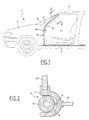
- FIG. 1 shows a front part of motor vehicle.
- This vehicle 1 comprises a chassis 3 to which is rigidly fixed a bodywork 5 defining a passenger compartment 7.
- a bodywork 5 defining a passenger compartment 7.
- the side uprights 9, as will be better seen in the following figure, are hollow, so that they can receive the upper part of a reinforcement bar 13 respectively.
- the reinforcing bar 13 which is produced in a material with high mechanical strength and good elastic characteristics, such as steel, stretches substantially from the chassis 3 to the roof 11.
- the bar 13 is rigidly fixed by its lower end to a part side of chassis 3, constituting a first element of structure, located substantially at the root of the root of the respective lateral upright 9. The fixing being carried out by example by welding or bolting.
- Reinforcement bar 13 extends, in its lower part, inside a body flank part 5 in one direction substantially vertical.
- the bar 13 is shown in its position corresponding to normal use of the vehicle, i.e. in which it is completely retracted into the bodywork 5, the upper part of the bar 13 being integrated in the respective lateral upright 9. In this position, the bar 13 is prestressed in bending, i.e. it is elastically deformed by relative to its nominal rest position in which the upper part of bar 13 is less inclined by compared to the vertical. The bar 13 is maintained in this bent position, in the absence of accidental overturning of the vehicle, by means of a locking member 15 shown on this figure in dotted lines.
- FIG 2 is a section in an orthogonal plane of a lateral upright 9 of the amount and the reinforcement bar 13, it can be seen that the upright 9 has a generally semi-circular section having an opening 17 made over the entire length of the upright 9 in the bending plane of the bar 13, and giving access to a gutter 19 constituting the hollow part of the upright 9 intended to receive the bar 13.
- the reinforcing bar 13 In the retracted position of the reinforcing bar 13, the latter is received in a complementary manner in the gutter 19 by means of a slight elastic deformation of the branches of the half-ring defined according to a section of the lateral upright 9.
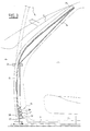
- the blocking member 15 consists of a cable which is, in the retracted position of the bar 13 (shown in solid lines) stretched between a lower end region of root 23 and the free upper end 25 of the bar 13.
- the cable 15 is secured, for example by welding, at the free end 24, while the other end of the cable is connected to the lower end region 23 of bar 13, constituting a second structural element.
- This last end of cable is associated with a quick release mechanism 25, making the blocking member 15 a blocking member says "quick release".
- a guide 26 is provided fixed to the structure, in the form of a half-ring in which is received the bar 13, but also the cable 15. Thus, this one is guided along the bar 13, so that the whole has a limited size.
- the quick release mechanism 25 includes a hook 27, forming retention means, pivotally mounted on a stud 28 secured to the lower end 23 of the bar 13, but which could be integral with any element of fixed structure with respect to the chassis 3.
- the hook 27 fits into a loop 29 at the end of the cable 15, forming attaches, when it is stretched, so as to maintain the bar 13 in bent position against the force of elastic bending reminder.
- the hook is tied mechanically to a pyrotechnic element 30 in the form a compartment in which a load is placed explosive, the triggering of which is controlled by an organ control electronics 31. Load initiation causes a sudden actuation of the hook 27 and a pivoting of it, so as to release it from the loop end 29 of cable 15, and thus free bar 13 from its bending stress.
- the electronic control unit 31 triggers the pyrotechnic element 30 in response to signals emitted by one or more vehicle rollover sensors, these sensors being known in the state of the art.
- the triggering of the pyrotechnic element 30 consequently causes the passage of the bar 13 of its position under bending stress and retracted into the amount 9, at its position extracted from amount 9 (such as shown in this Figure in phantom) and free from elastic return stress. Bar extraction 13 is done through the opening 17 (referenced on the Figure 2) with a slight elastic deformation of the branches amount 9.
- reinforcement bars 13 having a free end 24, but it is perfectly conceivable that the two bars 13 are connected, at the ends upper 24 by a crossbar so as to constitute an arch, the crossbar being received by example in the corresponding edge of the roof 11, and extracted of it analogously to what has just been described for bars 13 and side uprights 9.
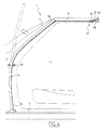
- FIG 4 there is shown a second mode of realization of the invention which does not differ from that described in reference to Figures 1 to 3 that in that the blocking member 15 extends into the roof 11 of the vehicle, the release 25 being disposed not in an end region lower 23 of bar 13, but in roof 11.
- This mode embodiment will therefore not be described in more detail.
- this embodiment applies to a vehicle with a fixed roof.
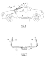
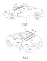
- FIG 5 there is shown schematically the front of a motor vehicle 1 fitted with a security corresponding to a third embodiment of the invention, in which the bars 13 are shaped and arranged analogously to what has been described in the two previous embodiments.
- the blocking member 35 is a bar rigid fixed at one of its ends to an element of structure 36 secured to chassis 3 via elements not shown, and at its other end to a free end region 24 of the reinforcement bar 13.
- this is prestressed in bending under the effect of the compressive force exerted by the rigid bar 35 (unlike the two previous embodiments where the blocking member 15 exerts a tensile force on the free end 24 of the bar 13).
- an element pyrotechnic 37 comprising an explosive charge
- the triggering is controlled by an electronic device control 31 analogous to what has been described previously, the explosive charge being adapted to cause, during its tripping, breaking the rigid bar 35.
- the triggering of the explosive charge in the event of accidental rollover of vehicle results in release of the reinforcement bar 13, namely its extraction from the corresponding side upright 9, and its return to a position free of elastic stress as it was shown in dashed lines.
- the rigid bar 35 is intended to be concealed inside the bodywork in normal operating condition of the vehicle.
- the reinforcing bars now designated under reference 43, are composed of two branches substantially orthogonal 43A, 43B.
- the first 43A of the branches extends substantially transversely to the vehicle and the second connected 43B constitutes the ground support part in overturning of the vehicle, i.e. it constitutes a part retracted in the amount 9 when the bar is in its retracted position.
- the first branch 43A constitutes a pre-stressed torsion bar in the retracted position of bar 43. Bar 43, to pass from its retracted position in the respective upright 9 at its position extracted, rotated around the axis materialized by torsion bar 43A.
- a part of the first branch 43A is rigidly fixed to a structural element 45, by welding, bolting, or all other suitable rigid assembly, said element of structure 45 being fixed relative to the chassis 3 and to the bodywork 5.
- the two torsion bars 43A of the two bars reinforcement 43 are actually formed by a bar single transverse fixed to the structural element 45 in a median transverse region.
- the vehicle comprises a fixed roof 11 in which is arranged the blocking 15, 35 of the cable 15 or rigid bar 35 type such as described in the previous embodiments, and actuated analogously which will therefore not be detailed further.
- the bar 43 is here extracted from amounts 9 in case of emergency by a couple of reminder of torsion generated by a torsional deformation of the bar torsion 43A.
- the torsion bar 43 consists of a bar also used for fixing the vehicle dashboard.
- a fifth mode of embodiment of the invention consists in providing a bar of torsion 53 constituted as in the previous case, of a first branch 53A transverse and a second branch 53B integrated into the respective upright 9 and extractable from it.
- the torsion bar 53A here consists of the windshield foot cross member, and the cross branch 53A of bar 53 acts as a torsion bar at the same while it fulfills the function of supporting the bay of windshield 21.
- FIG. 9 there is shown a sixth mode of realization of the invention applied by way of example to a convertible type vehicle.
- This embodiment is similar to the previous two in that the reinforcement bar 63 has two branches, the first of which 63A constitutes a torsion bar, and the second 63B is integrated in the upright 9. It differs in that the torsion bar 63A is assigned to the torsion bar function only for the safety device covered by the invention, this additional bar 63A being linked to installation 65 at a transverse bar 6 thanks to a rigid structural element.
- Bar 67 can be made up either of the cross member dashboard, on which the dashboard is fixed of the vehicle, which is used as a torsion bar in the fourth embodiment shown in Figure 6, or of the windshield foot cross member which supports the windshield 21 and which is used as a torsion bar in the fifth embodiment shown in Figure 8.
- the invention makes it possible to produce a device for safety which preserves the survival space of the occupants of a vehicle in the event of it being turned over, without work of complex means of extracting arches such that they are provided in known devices.
- energy is provided relatively small needed to break a balance mechanical, either by a release movement, or by a part rupture, the main part of mechanical energy necessary for the operation of the device being stored when assembling the vehicle.
- the role of the trigger system in operation of such a device is therefore reduced essentially an energy release function, and no to a function of supplying an extraction energy of reinforcement bars, which provides simplification important and increased reliability.
Landscapes
- Engineering & Computer Science (AREA)
- Mechanical Engineering (AREA)
- Body Structure For Vehicles (AREA)
- Lock And Its Accessories (AREA)
- Fuel Cell (AREA)
- Automatic Cycles, And Cycles In General (AREA)
Abstract
Description
- la barre est fixée par une partie de première
extrémité au premier élément de structure, tandis que
l'organe de blocage relie une partie de deuxième extrémité à un deuxième élément de structure, lorsque la barre est dans sa position escamotée ; - la partie de deuxième extrémité de la barre se situe, dans la position escamotée de la barre, dans une partie supérieure du montant respectif ;
- la barre est sensiblement rectiligne et déformée en flexion dans sa position escamotée.
- la barre comporte deux branches sensiblement orthogonales, dont une première s'étend suivant un axe sensiblement transversal du véhicule, et la deuxième est, dans la position escamotée de la barre, au moins partiellement escamotée dans le montant respectif, la partie de première extrémité appartenant à la première branche et la partie de deuxième extrémité appartenant à la deuxième branche, et la deuxième branche est déformée en torsion dans la position escamotée de la barre.
- l'organe de blocage s'étend, dans la position escamotée de la barre, sensiblement depuis la partie supérieure du montant jusqu'à une partie inférieure de flanc du véhicule ;
- le premier élément de structure se situe dans une partie inférieure de flanc du véhicule, et le deuxième élément de structure est soit confondu avec le premier élément de structure, soit constitué de la partie de première extrémité de la barre ;
- l'organe de blocage est un câble tendu, dans la position escamotée de la barre, entre la partie de deuxième extrémité de la barre et le deuxième élément de structure.
- l'organe de blocage est une barre rigide ;
- le véhicule comporte un toit fixe et l'organe de blocage s'étend dans ledit toit ;
- l'organe de blocage à libération rapide comporte un élément pyrotechnique relié à un organe de commande qui commande son déclenchement ;
- l'élément pyrotechnique est adapté pour provoquer, lors de son déclenchement, la rupture de l'organe de blocage ; et, en variante :
- l'organe de blocage présente une attache en engagement mutuel avec un moyen de rétention du deuxième élément de structure, formant la liaison entre l'organe de blocage du deuxième élément de structure, et l'élément pyrotechnique est adapté pour provoquer, lors de son déclenchement, le dégagement de l'attache par rapport au moyen de rétention.
- la Figure 1 est une vue schématique en coupe dans un plan longitudinal d'une partie avant d'un véhicule suivant un premier mode de réalisation de l'invention ;
- la Figure 2 est une vue en coupe à plus grande échelle, suivant la ligne 2-2 d'un montant et d'une barre de renfort représentés à la Figure 1 ;
- la Figure 3 est une vue à plus grande échelle de la barre de renfort représentée à la Figure 1 et de l'organe de blocage associé ;
- la Figure 4 est une vue analogue à la Figure 1 suivant un deuxième mode de réalisation de l'invention ;
- la Figure 5 est une vue analogue suivant un troisième mode de réalisation de l'invention ;
- la Figure 6 est une vue analogue suivant un quatrième mode de réalisation de l'invention ;
- la Figure 7 est une vue de face, suivant la direction F indiquée sur la Figure 6, des barres de renfort et de l'élément de structure sur lequel elles sont fixées, seuls ;
- la Figure 8 une vue analogue à la Figure 6 suivant un cinquième mode de réalisation de l'invention ; et
- la Figure 9 est une vue en perspective d'un véhicule suivant un sixième mode de réalisation de l'invention.
Claims (13)
- Véhicule automobile comprenant un châssis (3) sur lequel sont fixés rigidement des éléments de structure, dont une carrosserie (5) présentant une paire de montants latéraux creux (9) formant support pour un pare-brise (21), le véhicule comprenant en outre un dispositif de sécurité destiné à préserver la carrosserie (5) d'un effet d'écrasement lors d'un retournement accidentel du véhicule, ledit dispositif de sécurité comportant deux barres de renfort (13 ; 43 ; 53 ; 63), chacune desdites barres étant déplaçable d'une position escamotée dans laquelle elle est escamotée au moins partiellement dans un montant latéral respectif (9), à une position de protection dans laquelle elle fait saillie au moins partiellement dudit montant (9), caractérisé en ce que la barre (13 ; 43 ; 53 ; 63) est fixée rigidement à un premier élément de structure (3 ;45 ;63 , 65), ladite barre étant, dans sa position escamotée, déformée élastiquement et maintenue en position à l'encontre de l'effort de rappel élastique ainsi créé par au moins un organe de blocage (15 ;35) à libération rapide, et dans sa position de protection, libre de contrainte de rappel élastique.
- Véhicule automobile suivant la revendication 1, caractérisé en ce que la barre (13 ; 43 ; 53 ; 63) est fixée par une partie de première extrémité (23 ; 43A ; 53A ; 63A) au premier élément de structure (3 ; 45 ; 63, 65) , tandis que l'organe de blocage (15 ; 35) relie une partie de deuxième extrémité (24 ; 43B ; 53B ; 63B) à un deuxième élément de structure (3 ; 23 ; 36), lorsque la barre (13 ; 43 ; 53 ; 63) est dans sa position escamotée.
- Véhicule automobile suivant la revendication 2, caractérisé en ce que la partie de deuxième extrémité (24 ; 43B ; 53B ; 63B) de la barre (13 ; 43 ; 53 ; 63) se situe, dans la position escamotée de la barre, dans une partie supérieure du montant respectif (9).
- Véhicule automobile suivant la revendication 2 ou 3, caractérisé en ce que la barre (13) est sensiblement rectiligne et déformée en flexion dans sa position escamotée.
- Véhicule automobile suivant la revendication 2 ou 3, caractérisé en ce que la barre ( 43 ; 53 ; 63) comporte deux branches (43A, 43B ; 53A, 53B ; 63A, 63B) sensiblement orthogonales, dont une première (43A ; 53A ; 63A) s'étend suivant un axe sensiblement transversal du véhicule, et la deuxième est, dans la position escamotée de la barre, au moins partiellement escamotée dans le montant respectif (9), la partie de première extrémité appartenant à la première branche (43A ; 53A ; 63A) et la partie de deuxième extrémité appartenant à la deuxième branche (43B ; 53B ; 63B), et la deuxième branche (43B ; 53B ; 63B) est déformée en torsion dans la position escamotée de la barre.
- Véhicule automobile suivant la revendication 4 ou 5, caractérisé en ce que l'organe de blocage (15; 35) s'étend, dans la position escamotée de la barre (13), sensiblement depuis la partie supérieure du montant (9) jusqu'à une partie inférieure de flanc du véhicule.
- Véhicule automobile suivant les revendications 4 et 6 prises ensemble, caractérisé en ce que le premier élément de structure (3) se situe dans une partie inférieure de flanc du véhicule, et le deuxième élément de structure (3, 23) est soit confondu avec le premier élément de structure (3), soit constitué de la partie de première extrémité (23) de la barre (13).
- Véhicule automobile suivant l'une quelconque des revendications 3 à 7, caractérisé en ce que l'organe de blocage (15) est un câble tendu, dans la position escamotée de la barre (13 ; 43 ; 53 ; 63), entre la partie de deuxième extrémité (24 ; 43B ; 53B ; 63B) de la barre (13 ; 43 ; 53 ; 63) et le deuxième élément de structure (3, 23 ;36).
- Véhicule automobile suivant l'une quelconque des revendications 3 à 7, caractérisé en ce que l'organe de blocage (35) est une barre rigide.
- Véhicule automobile suivant l'une quelconque des revendications 1 à 9, comportant un toit fixe (11), caractérisé en ce que l'organe de blocage (15; 35) s'étend dans ledit toit (11).
- Véhicule automobile suivant l'une quelconque des revendications 1 à 10, caractérisé en ce que l'organe de blocage (15 ;35) à libération rapide comporte un élément pyrotechnique (30) relié à un organe de commande (31) qui commande son déclenchement.
- Véhicule automobile suivant la revendication 11, caractérisé en ce que l'élément pyrotechnique (30) est adapté pour provoquer, lors de son déclenchement, la rupture de l'organe de blocage (35).
- Véhicule automobile suivant la revendication 11, caractérisé en ce que l'organe de blocage (15) présente une attache (29) en engagement mutuel avec un moyen de rétention (27) du deuxième élément de structure (3, 23), formant la liaison entre l'organe de blocage (15) et le deuxième élément de structure (3, 23) , et l'élément pyrotechnique (30) est adapté pour provoquer, lors de son déclenchement, le dégagement de l'attache (29) par rapport au moyen de rétention (27).
Applications Claiming Priority (2)
| Application Number | Priority Date | Filing Date | Title |
|---|---|---|---|
| FR0012313 | 2000-09-27 | ||
| FR0012313A FR2814412B1 (fr) | 2000-09-27 | 2000-09-27 | Vehicule automobile equipe de barres de protection d'habitacle extractibles |
Publications (3)
| Publication Number | Publication Date |
|---|---|
| EP1193137A2 true EP1193137A2 (fr) | 2002-04-03 |
| EP1193137A3 EP1193137A3 (fr) | 2003-01-22 |
| EP1193137B1 EP1193137B1 (fr) | 2007-10-17 |
Family
ID=8854747
Family Applications (1)
| Application Number | Title | Priority Date | Filing Date |
|---|---|---|---|
| EP01402254A Expired - Lifetime EP1193137B1 (fr) | 2000-09-27 | 2001-08-29 | Véhicule automobile équipé de barres de protection d'habitacle extractibles |
Country Status (4)
| Country | Link |
|---|---|
| EP (1) | EP1193137B1 (fr) |
| AT (1) | ATE375899T1 (fr) |
| DE (1) | DE60130955D1 (fr) |
| FR (1) | FR2814412B1 (fr) |
Cited By (4)
| Publication number | Priority date | Publication date | Assignee | Title |
|---|---|---|---|---|
| EP1277647A1 (fr) * | 2001-07-18 | 2003-01-22 | Mazda Motor Corporation | Structure pour cabriolet |
| FR2868373A1 (fr) * | 2004-04-06 | 2005-10-07 | Peugeot Citroen Automobiles Sa | Structure d'habitacle de vehicule automobile comprenant un montant escamotable |
| DE102005024905A1 (de) * | 2005-05-31 | 2006-12-07 | Volkswagen Ag | Sicherheitseinrichtung für ein Cabrio-Kraftfahrzeug |
| DE102007006534A1 (de) * | 2007-02-09 | 2008-08-14 | Webasto Ag | Fahrzeug mit einem ableg- und/oder abnehmbaren Dach |
Family Cites Families (4)
| Publication number | Priority date | Publication date | Assignee | Title |
|---|---|---|---|---|
| DE8406461U1 (de) * | 1984-08-02 | Eller, Philipp, 6107 Reinheim | Kraftfahrzeugkarosserie für offene Kraftfahrzeuge | |
| DE19511400C2 (de) * | 1995-03-28 | 1997-03-27 | Hs Tech & Design | Vorrichtung zum Überrollschutz eines offenen Cabrio-Fahrzeuges |
| DE19514551A1 (de) * | 1995-04-20 | 1996-10-24 | Bayerische Motoren Werke Ag | Personenkraftwagen, insbesondere Cabriolet, mit einem Überrollschutz |
| DE19533322A1 (de) * | 1995-09-08 | 1997-03-13 | Bayerische Motoren Werke Ag | Vorrichtung zur Erhöhung der Knicksteifigkeit von A-Säulen von Kraftfahrzeugen, insbesondere von Cabriolets |
-
2000
- 2000-09-27 FR FR0012313A patent/FR2814412B1/fr not_active Expired - Fee Related
-
2001
- 2001-08-29 DE DE60130955T patent/DE60130955D1/de not_active Expired - Lifetime
- 2001-08-29 EP EP01402254A patent/EP1193137B1/fr not_active Expired - Lifetime
- 2001-08-29 AT AT01402254T patent/ATE375899T1/de not_active IP Right Cessation
Non-Patent Citations (1)
| Title |
|---|
| None |
Cited By (5)
| Publication number | Priority date | Publication date | Assignee | Title |
|---|---|---|---|---|
| EP1277647A1 (fr) * | 2001-07-18 | 2003-01-22 | Mazda Motor Corporation | Structure pour cabriolet |
| US6764124B2 (en) | 2001-07-18 | 2004-07-20 | Mazda Motor Corporation | Body structure for convertible car |
| FR2868373A1 (fr) * | 2004-04-06 | 2005-10-07 | Peugeot Citroen Automobiles Sa | Structure d'habitacle de vehicule automobile comprenant un montant escamotable |
| DE102005024905A1 (de) * | 2005-05-31 | 2006-12-07 | Volkswagen Ag | Sicherheitseinrichtung für ein Cabrio-Kraftfahrzeug |
| DE102007006534A1 (de) * | 2007-02-09 | 2008-08-14 | Webasto Ag | Fahrzeug mit einem ableg- und/oder abnehmbaren Dach |
Also Published As
| Publication number | Publication date |
|---|---|
| EP1193137B1 (fr) | 2007-10-17 |
| FR2814412B1 (fr) | 2002-12-20 |
| FR2814412A1 (fr) | 2002-03-29 |
| EP1193137A3 (fr) | 2003-01-22 |
| ATE375899T1 (de) | 2007-11-15 |
| DE60130955D1 (de) | 2007-11-29 |
Similar Documents
| Publication | Publication Date | Title |
|---|---|---|
| EP1778524B1 (fr) | Dispositif de securite en cas de retournement de vehicule | |
| FR2931403A1 (fr) | Dispositif d'absorption de choc et siege comportant un tel dispositif | |
| FR2795372A1 (fr) | Dispositif d'articulation de siege a verrouillage d'urgence et siege de vehicule l'incorporant | |
| EP1108580B1 (fr) | Hayon de véhicule automobile | |
| FR2673897A1 (fr) | Element de protection au retournement pour des automobiles. | |
| EP2440728B1 (fr) | Poignée d'un ouvrant de véhicule automobile | |
| EP1193137B1 (fr) | Véhicule automobile équipé de barres de protection d'habitacle extractibles | |
| EP0532378B1 (fr) | Dispositif de retenue pour un passager occupant la place centrale arrière d'un véhicule automobile | |
| WO2020020656A1 (fr) | Poignée d'ouvrant de véhicule automobile munie d'un système de sécurité inertiel | |
| EP0753450A1 (fr) | Dispositif pour la protection d'un occupant d'un véhicule automobile en cas de choc latéral | |
| WO2006111623A1 (fr) | Dispositif de protection a arceau(x) articule(s) | |
| EP1606152B1 (fr) | Dispositif de montage d une pedale de vehicule automobile | |
| FR2848929A1 (fr) | Dispositif de verrouillage renforce notamment de siege arriere rabattable de vehicule automobile. | |
| FR2824799A1 (fr) | Siege de vehicule dote d'un dispositif de protection du cou en cas d'accident | |
| EP1394002B1 (fr) | Dispositif de prétention d'une ceinture de sécurité, siège de véhicule automobile et véhicule automobile comprenant un tel dispositif | |
| FR2609948A1 (fr) | Dispositif de verrouillage a inertie pour siege de vehicule | |
| FR2796897A1 (fr) | Siege de vehicule automobile deverrouillable dote d'un dossier rabattable, et vehicule comportant un tel siege | |
| FR2851523A1 (fr) | Siege de vehicule automobile retractable en cas de choc ou de retournement | |
| FR2883521A1 (fr) | Siege de vehicule deplacable en avant, comprenant un support et un dossier rabattable ver l'avant | |
| EP2949616B1 (fr) | Mât télescopique à dispositif de sécurité intégré pour appareil de levage, et appareil de levage equipé d'un tel mât télescopique | |
| FR3161237A1 (fr) | Mécanisme de commande d’ouverture pour portière latérale de véhicule comprenant une masselotte de verrouillage inertielle avec portion fusible | |
| FR3102715A1 (fr) | Pare-soleil pour véhicule automobile et véhicule automobile comportant un tel équipement | |
| EP1946980B1 (fr) | Dispositif de protection des piétons en cas de choc frontal avec un véhicule automobile et véhicule automobile équipé d'un tel disspositif de protection des piétons | |
| EP1870299A1 (fr) | Dispositif de sécurité en gas de retournement d'un véhicule | |
| FR2936981A1 (fr) | Dispositif de toit ouvrant a commande manuelle pour vehicule notamment de type automobile |
Legal Events
| Date | Code | Title | Description |
|---|---|---|---|
| PUAI | Public reference made under article 153(3) epc to a published international application that has entered the european phase |
Free format text: ORIGINAL CODE: 0009012 |
|
| AK | Designated contracting states |
Kind code of ref document: A2 Designated state(s): AT BE CH CY DE DK ES FI FR GB GR IE IT LI LU MC NL PT SE TR |
|
| AX | Request for extension of the european patent |
Free format text: AL;LT;LV;MK;RO;SI |
|
| PUAL | Search report despatched |
Free format text: ORIGINAL CODE: 0009013 |
|
| AK | Designated contracting states |
Kind code of ref document: A3 Designated state(s): AT BE CH CY DE DK ES FI FR GB GR IE IT LI LU MC NL PT SE TR |
|
| AX | Request for extension of the european patent |
Free format text: AL;LT;LV;MK;RO;SI |
|
| 17P | Request for examination filed |
Effective date: 20030628 |
|
| AKX | Designation fees paid |
Designated state(s): AT BE CH CY DE DK ES FI FR GB GR IE IT LI LU MC NL PT SE TR |
|
| GRAP | Despatch of communication of intention to grant a patent |
Free format text: ORIGINAL CODE: EPIDOSNIGR1 |
|
| GRAS | Grant fee paid |
Free format text: ORIGINAL CODE: EPIDOSNIGR3 |
|
| GRAA | (expected) grant |
Free format text: ORIGINAL CODE: 0009210 |
|
| AK | Designated contracting states |
Kind code of ref document: B1 Designated state(s): AT BE CH CY DE DK ES FI FR GB GR IE IT LI LU MC NL PT SE TR |
|
| REG | Reference to a national code |
Ref country code: GB Ref legal event code: FG4D Free format text: NOT ENGLISH |
|
| REG | Reference to a national code |
Ref country code: CH Ref legal event code: EP |
|
| REG | Reference to a national code |
Ref country code: IE Ref legal event code: FG4D Free format text: LANGUAGE OF EP DOCUMENT: FRENCH |
|
| REF | Corresponds to: |
Ref document number: 60130955 Country of ref document: DE Date of ref document: 20071129 Kind code of ref document: P |
|
| NLV1 | Nl: lapsed or annulled due to failure to fulfill the requirements of art. 29p and 29m of the patents act | ||
| PG25 | Lapsed in a contracting state [announced via postgrant information from national office to epo] |
Ref country code: SE Free format text: LAPSE BECAUSE OF FAILURE TO SUBMIT A TRANSLATION OF THE DESCRIPTION OR TO PAY THE FEE WITHIN THE PRESCRIBED TIME-LIMIT Effective date: 20080117 Ref country code: NL Free format text: LAPSE BECAUSE OF FAILURE TO SUBMIT A TRANSLATION OF THE DESCRIPTION OR TO PAY THE FEE WITHIN THE PRESCRIBED TIME-LIMIT Effective date: 20071017 Ref country code: ES Free format text: LAPSE BECAUSE OF FAILURE TO SUBMIT A TRANSLATION OF THE DESCRIPTION OR TO PAY THE FEE WITHIN THE PRESCRIBED TIME-LIMIT Effective date: 20080128 |
|
| GBV | Gb: ep patent (uk) treated as always having been void in accordance with gb section 77(7)/1977 [no translation filed] | ||
| PG25 | Lapsed in a contracting state [announced via postgrant information from national office to epo] |
Ref country code: PT Free format text: LAPSE BECAUSE OF FAILURE TO SUBMIT A TRANSLATION OF THE DESCRIPTION OR TO PAY THE FEE WITHIN THE PRESCRIBED TIME-LIMIT Effective date: 20080317 |
|
| REG | Reference to a national code |
Ref country code: IE Ref legal event code: FD4D |
|
| PG25 | Lapsed in a contracting state [announced via postgrant information from national office to epo] |
Ref country code: AT Free format text: LAPSE BECAUSE OF FAILURE TO SUBMIT A TRANSLATION OF THE DESCRIPTION OR TO PAY THE FEE WITHIN THE PRESCRIBED TIME-LIMIT Effective date: 20071017 |
|
| PG25 | Lapsed in a contracting state [announced via postgrant information from national office to epo] |
Ref country code: DK Free format text: LAPSE BECAUSE OF FAILURE TO SUBMIT A TRANSLATION OF THE DESCRIPTION OR TO PAY THE FEE WITHIN THE PRESCRIBED TIME-LIMIT Effective date: 20071017 |
|
| PLBE | No opposition filed within time limit |
Free format text: ORIGINAL CODE: 0009261 |
|
| STAA | Information on the status of an ep patent application or granted ep patent |
Free format text: STATUS: NO OPPOSITION FILED WITHIN TIME LIMIT |
|
| 26N | No opposition filed |
Effective date: 20080718 |
|
| PG25 | Lapsed in a contracting state [announced via postgrant information from national office to epo] |
Ref country code: DE Free format text: LAPSE BECAUSE OF FAILURE TO SUBMIT A TRANSLATION OF THE DESCRIPTION OR TO PAY THE FEE WITHIN THE PRESCRIBED TIME-LIMIT Effective date: 20080118 Ref country code: IE Free format text: LAPSE BECAUSE OF FAILURE TO SUBMIT A TRANSLATION OF THE DESCRIPTION OR TO PAY THE FEE WITHIN THE PRESCRIBED TIME-LIMIT Effective date: 20071017 |
|
| PG25 | Lapsed in a contracting state [announced via postgrant information from national office to epo] |
Ref country code: GB Free format text: LAPSE BECAUSE OF FAILURE TO SUBMIT A TRANSLATION OF THE DESCRIPTION OR TO PAY THE FEE WITHIN THE PRESCRIBED TIME-LIMIT Effective date: 20071017 |
|
| PG25 | Lapsed in a contracting state [announced via postgrant information from national office to epo] |
Ref country code: GR Free format text: LAPSE BECAUSE OF FAILURE TO SUBMIT A TRANSLATION OF THE DESCRIPTION OR TO PAY THE FEE WITHIN THE PRESCRIBED TIME-LIMIT Effective date: 20080118 |
|
| PG25 | Lapsed in a contracting state [announced via postgrant information from national office to epo] |
Ref country code: FI Free format text: LAPSE BECAUSE OF FAILURE TO SUBMIT A TRANSLATION OF THE DESCRIPTION OR TO PAY THE FEE WITHIN THE PRESCRIBED TIME-LIMIT Effective date: 20071017 |
|
| PG25 | Lapsed in a contracting state [announced via postgrant information from national office to epo] |
Ref country code: MC Free format text: LAPSE BECAUSE OF NON-PAYMENT OF DUE FEES Effective date: 20080831 |
|
| REG | Reference to a national code |
Ref country code: CH Ref legal event code: PL |
|
| REG | Reference to a national code |
Ref country code: FR Ref legal event code: ST Effective date: 20090430 |
|
| PG25 | Lapsed in a contracting state [announced via postgrant information from national office to epo] |
Ref country code: LI Free format text: LAPSE BECAUSE OF NON-PAYMENT OF DUE FEES Effective date: 20080831 Ref country code: CH Free format text: LAPSE BECAUSE OF NON-PAYMENT OF DUE FEES Effective date: 20080831 |
|
| PG25 | Lapsed in a contracting state [announced via postgrant information from national office to epo] |
Ref country code: CY Free format text: LAPSE BECAUSE OF FAILURE TO SUBMIT A TRANSLATION OF THE DESCRIPTION OR TO PAY THE FEE WITHIN THE PRESCRIBED TIME-LIMIT Effective date: 20071017 Ref country code: BE Free format text: LAPSE BECAUSE OF NON-PAYMENT OF DUE FEES Effective date: 20080831 |
|
| PG25 | Lapsed in a contracting state [announced via postgrant information from national office to epo] |
Ref country code: FR Free format text: LAPSE BECAUSE OF NON-PAYMENT OF DUE FEES Effective date: 20080901 |
|
| PG25 | Lapsed in a contracting state [announced via postgrant information from national office to epo] |
Ref country code: LU Free format text: LAPSE BECAUSE OF NON-PAYMENT OF DUE FEES Effective date: 20080829 |
|
| PG25 | Lapsed in a contracting state [announced via postgrant information from national office to epo] |
Ref country code: TR Free format text: LAPSE BECAUSE OF FAILURE TO SUBMIT A TRANSLATION OF THE DESCRIPTION OR TO PAY THE FEE WITHIN THE PRESCRIBED TIME-LIMIT Effective date: 20071017 |
|
| PG25 | Lapsed in a contracting state [announced via postgrant information from national office to epo] |
Ref country code: IT Free format text: LAPSE BECAUSE OF NON-PAYMENT OF DUE FEES Effective date: 20080831 |