EP1191653A2 - Feuerfester Kabelkanal, Verfahren zu seiner Herstellung sowie dafür geeignete Zwischenprodukte - Google Patents
Feuerfester Kabelkanal, Verfahren zu seiner Herstellung sowie dafür geeignete Zwischenprodukte Download PDFInfo
- Publication number
- EP1191653A2 EP1191653A2 EP01120945A EP01120945A EP1191653A2 EP 1191653 A2 EP1191653 A2 EP 1191653A2 EP 01120945 A EP01120945 A EP 01120945A EP 01120945 A EP01120945 A EP 01120945A EP 1191653 A2 EP1191653 A2 EP 1191653A2
- Authority
- EP
- European Patent Office
- Prior art keywords
- folds
- grooves
- cover plates
- plates
- cable duct
- Prior art date
- Legal status (The legal status is an assumption and is not a legal conclusion. Google has not performed a legal analysis and makes no representation as to the accuracy of the status listed.)
- Withdrawn
Links
Images



Classifications
-
- H—ELECTRICITY
- H02—GENERATION; CONVERSION OR DISTRIBUTION OF ELECTRIC POWER
- H02G—INSTALLATION OF ELECTRIC CABLES OR LINES, OR OF COMBINED OPTICAL AND ELECTRIC CABLES OR LINES
- H02G3/00—Installations of electric cables or lines or protective tubing therefor in or on buildings, equivalent structures or vehicles
- H02G3/02—Details
- H02G3/04—Protective tubing or conduits, e.g. cable ladders or cable troughs
- H02G3/0406—Details thereof
- H02G3/0412—Heat or fire protective means
Definitions
- the present invention relates to a fire-proof cable duct based of gypsum fibreboard and process for its manufacture and for it suitable intermediates.
- Fireproof cable ducts are increasingly required, especially in public buildings, but also increasingly in high-rise buildings and on ships.
- Refractory channels have already been made from Gypsum fibreboards, which can be processed and processed in a similar way Way like wood, but with the advantage of being fire-proof.
- Such Cable ducts have so far been individually tailored to the respective needs accordingly made from larger plates, which accordingly were tailored.
- DE-A-37 07 255 describes a fire protection device for cable routes as well a method for their production is known, in which the cables with the help of Plate elements are encased in such a way that a closed channel the cables are formed around, and the cables being inserted into and before closing the channel formed by the plate elements with be coated with a fire-retardant material.
- the plates exist preferably made of mineral fiber boards with fiber cement on both sides are coated. Gas concrete slabs with and are mentioned as further materials without cement coating, plasterboard or gypsum fibreboard. From the Plate elements are preferably three to one already in the factory U-shaped gutter put together in this pre-assembled state to the Construction site is transported.
- the cables After inserting the cables into the U-shaped channel the cables are coated with a fire-insulating material, so that deposits a relatively even layer on top of the cable. Then the U-shaped channel is made by placing the cover plate element locked.
- the plate elements preferably have at their upper edges and bottom edges of inward folds. There is none Note on how the plate elements are connected together in the factory become.
- the invention has set itself the task of fireproof cable ducts based on To provide gypsum fiberboard that is made from prefabricated and factory cut parts consist of these and the cable ducts quickly, however can be easily and flexibly manufactured on site. Thereby the The number of different parts should be kept as low as possible Manufacturing, transportation and storage as easy and inexpensive as possible shape. These standardized parts should then be easier and the required cable duct can be reliably produced, the is designed to be suspended from the ceiling of the room, for example, or else can be attached to the floor. Furthermore, the cable duct is said to be simpler Way angled, branched, expanded or tapered, being in turn, prefabricated standardized parts are to be used.
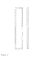
- the cable duct is assembled from prefabricated side walls, which on their upper edges and on their Bottom edges each have inward folds as well as Bottom plates and cover plates that fold to their side edges have matching upward or downward grooves.
- folds and grooves of all plates have approximately that half the thickness of the gypsum fibreboard so that they always fit together and can be processed together in any way.
- the cable duct is preferably held together by brackets wide head, which from below through aligned holes in the Base plates and the cover plates can be pushed through.
- brackets can for example be designed to be suspended from the ceiling of the room. But they can also be attached to the floor and are then from above pressed together.
- Pieces made of are particularly suitable as a wide head Gypsum fibreboard, which have a borehole thread in the middle. This Threads can either be cut into the gypsum fibreboard or made of them consist of a metal sleeve that fits into the central borehole and there is attached.
- the refractory cable duct according to the invention is made by the parts made of gypsum fibreboard with prefabricated folds and grooves put together and then through the wide-headed brackets aligned holes in base plates and cover plates with each other get connected.
- the individual sections of the cable duct are so put together that preferably a smooth wall inside and outside arises, but the joints between the sections are angled twice and thus effectively prevent the passage of smoke or hot gases.
- Hanging on the ceiling of the room or fixing to the floor can for example, by pegging the brackets. But it can also screwable or attachable fasteners are used.
- the aligned holes required for suspension or fastening in the base plates and cover plates can be manufactured on site. It is more advantageous, however, that these bores are already standardized at the factory to make and then ensure that the suspension on the ceiling or Attachment to the floor in the appropriate standardized intervals.
Landscapes
- Engineering & Computer Science (AREA)
- Architecture (AREA)
- Civil Engineering (AREA)
- Structural Engineering (AREA)
- Installation Of Indoor Wiring (AREA)
- Details Of Indoor Wiring (AREA)
- Building Environments (AREA)
Abstract
Description
Claims (9)
- Feuerfester Kabelkanal auf Basis von Gipsfaserplatten, dadurch gekennzeichnet, dass er zusammengesetzt ist aus vorgefertigten Seitenwänden, die an ihren Oberkanten und ihren Unterkanten jeweils nach innen gerichtete Falze aufweisen, sowie aus Bodenplatten und Abdeckplatten, die an ihren Seitenkanten zu den Falzen passende nach oben bzw. nach unten weisende Nuten aufweisen.
- Feuerfester Kabelkanal gemäß Anspruch 1, dadurch gekennzeichnet, dass er aus einzelnen, abdichtend zusammensteckbaren Abschnitten besteht, indem ein oder beide Enden aller Platten Falze aufweisen, die abwechselnd innen oder außen angebracht sind.
- Feuerfester Kabelkanal gemäß Anspruch 1 oder 2, dadurch gekennzeichnet, dass Falze und Nuten aller Platten etwa der halben Stärke der Gipsfaserplatten entsprechen.
- Feuerfester Kabelkanal gemäß einem der Ansprüche 1 bis 3, dadurch gekennzeichnet, dass er zusammengehalten wird durch Halterungen mit breitem Kopf, welche von unten durch fluchtende Bohrungen in den Bodenplatten und den Abdeckplatten durchsteckbar und gewünschtenfalls an der Decke des Raumes aufhängbar ausgestaltet oder am Boden befestigt sind.
- Feuerfester Kabelkanal gemäß Anspruch 4, dadurch gekennzeichnet, dass der breite Kopf aus einem Stück Gipsfaserplatte besteht, welches in seiner Mitte ein Bohrloch mit Gewinde aufweist.
- Feuerfester Kabelkanal gemäß einem der Ansprüche 1 bis 5, dadurch gekennzeichnet, dass Abwinkelungen, Verzweigungen, Erweiterungen und Verjüngungen aus Seitenwänden sowie Bodenplatten und Abdeckplatten bestehen, deren Falze und Nuten entsprechend versetzt angebracht sind.
- Verfahren zur Herstellung von feuerfesten Kabelkanälen gemäß einem der Ansprüche 1 bis 6, dadurch gekennzeichnet, dass Gipsfaserplatten mit werksseitig vorgefertigten Falzen und Nuten zusammengesteckt und durch Halterungen mit breitem Kopf durch fluchtende Bohrungen in den Bodenplatten und den Abdeckplatten miteinander verbunden werden, woraufhin sie gewünschtenfalls an der Decke des Raumes aufgehängt oder am Boden befestigt werden.
- Werkseitig vorgefertigte Boden- und Abdeckplatten für feuerfeste Kabelkanäle gemäß Anspruch 3, gekennzeichnet durch nach oben bzw. nach unten weisende Nuten an den Seitenkanten, welche der halben Stärke der Gipsfaserplatten entsprechen.
- Werkseitig vorgefertigte Seitenwände sowie Boden- und Abdeckplatten für Abwinkelungen, Verzweigungen, Erweiterungen und Verjüngungen der Kabelkanäle gemäß Anspruch 6, bestehend aus Gipsfaserplatten mit entsprechend versetzten Falzen und Nuten.
Applications Claiming Priority (2)
| Application Number | Priority Date | Filing Date | Title |
|---|---|---|---|
| DE10046431 | 2000-09-20 | ||
| DE10046431A DE10046431C1 (de) | 2000-09-20 | 2000-09-20 | Feuerfester Kabelkanal, Verfahren zu seiner Herstellung sowie dafür geeignete Zwischenprodukte |
Publications (2)
| Publication Number | Publication Date |
|---|---|
| EP1191653A2 true EP1191653A2 (de) | 2002-03-27 |
| EP1191653A3 EP1191653A3 (de) | 2004-01-28 |
Family
ID=7656854
Family Applications (1)
| Application Number | Title | Priority Date | Filing Date |
|---|---|---|---|
| EP01120945A Withdrawn EP1191653A3 (de) | 2000-09-20 | 2001-08-31 | Feuerfester Kabelkanal, Verfahren zu seiner Herstellung sowie dafür geeignete Zwischenprodukte |
Country Status (7)
| Country | Link |
|---|---|
| EP (1) | EP1191653A3 (de) |
| CZ (1) | CZ20013374A3 (de) |
| DE (1) | DE10046431C1 (de) |
| HU (1) | HUP0103733A3 (de) |
| NO (1) | NO20014551L (de) |
| PL (1) | PL349587A1 (de) |
| RU (1) | RU2233521C2 (de) |
Cited By (1)
| Publication number | Priority date | Publication date | Assignee | Title |
|---|---|---|---|---|
| EP3068003A1 (de) | 2015-03-11 | 2016-09-14 | RF-Technologies | Gipsplattenanordnung |
Families Citing this family (1)
| Publication number | Priority date | Publication date | Assignee | Title |
|---|---|---|---|---|
| GB2391716B (en) * | 2002-08-02 | 2005-12-14 | Environmental Seals Ltd | Fireproofed covers for conduit fittings |
Family Cites Families (5)
| Publication number | Priority date | Publication date | Assignee | Title |
|---|---|---|---|---|
| SU801169A1 (ru) * | 1979-04-16 | 1981-01-30 | Отделение Дальних Передач Орденаоктябрьской Революции Всесоюзногогосударственного Проектно-Изыскатель-Ского И Научно-Исследовательскогоинститута Энергетических Систем Иэлектрических Сетей "Энергосетьпроект" | Канал дл прокладки коммуникаций |
| DE3538844A1 (de) * | 1985-10-31 | 1987-05-07 | Pct Pyrochemtek Ag | Bausatz zur herstellung von brandhemmenden kabelkanaelen |
| DE3707255A1 (de) * | 1987-03-06 | 1988-09-15 | Gruenzweig & Hartmann Montage | Brandschutzvorrichtung fuer kabeltrassen sowie verfahren zu ihrer herstellung |
| DE4036792C1 (de) * | 1990-11-19 | 1991-12-19 | Dmt Marinetechnik Gmbh, 2000 Hamburg, De | |
| DE9310405U1 (de) * | 1993-01-13 | 1993-12-02 | PBS Planung für Betriebssicherheit und -Service GmbH, 93474 Arrach | Kabelkanal und Kanalelement für einen solchen Kanal |
-
2000
- 2000-09-20 DE DE10046431A patent/DE10046431C1/de not_active Expired - Fee Related
-
2001
- 2001-08-31 EP EP01120945A patent/EP1191653A3/de not_active Withdrawn
- 2001-09-10 PL PL01349587A patent/PL349587A1/xx unknown
- 2001-09-19 CZ CZ20013374A patent/CZ20013374A3/cs unknown
- 2001-09-19 RU RU2001125690/09A patent/RU2233521C2/ru not_active IP Right Cessation
- 2001-09-19 HU HU0103733A patent/HUP0103733A3/hu unknown
- 2001-09-19 NO NO20014551A patent/NO20014551L/no not_active Application Discontinuation
Cited By (1)
| Publication number | Priority date | Publication date | Assignee | Title |
|---|---|---|---|---|
| EP3068003A1 (de) | 2015-03-11 | 2016-09-14 | RF-Technologies | Gipsplattenanordnung |
Also Published As
| Publication number | Publication date |
|---|---|
| EP1191653A3 (de) | 2004-01-28 |
| HUP0103733A3 (en) | 2002-06-28 |
| HUP0103733A2 (hu) | 2002-05-29 |
| HU0103733D0 (en) | 2001-11-28 |
| RU2233521C2 (ru) | 2004-07-27 |
| NO20014551L (no) | 2002-03-21 |
| PL349587A1 (en) | 2002-03-25 |
| DE10046431C1 (de) | 2002-03-14 |
| CZ20013374A3 (cs) | 2002-06-12 |
| NO20014551D0 (no) | 2001-09-19 |
Similar Documents
| Publication | Publication Date | Title |
|---|---|---|
| DE102017118005A1 (de) | Trockenbau-Trennwandsystem sowie Verfahren zur Montage eines derartigen Trockenbau-Trennwandsystems | |
| DE3444881A1 (de) | Schallabsorbierender gebaeudewand- bzw. -deckenaufbau | |
| DE8416967U1 (de) | Daemmplatte fuer kellerdecken und dgl. sowie kellerdecke selbst | |
| EP1525358B1 (de) | Dämmschicht aus mineralfasern und gebäudewand | |
| DE10046431C1 (de) | Feuerfester Kabelkanal, Verfahren zu seiner Herstellung sowie dafür geeignete Zwischenprodukte | |
| DE69421428T2 (de) | Paneel für die Bauindustrie | |
| DE102017118004A1 (de) | Trockenbau-Trennwandsystem sowie Verfahren zur Montage eines derartigen Trockenbau-Trennwandsystems | |
| DE9318466U1 (de) | Verbundelement, insbesondere Verbundplatte, für Bauzwecke | |
| EP2820197B1 (de) | Dämmelement | |
| DE19950356C2 (de) | Mehrschichtige Bauplatte, sowie Verfahren zu ihrer Herstellung | |
| DE102016001213A1 (de) | Hölzernes Deckenelement | |
| DE10302983B4 (de) | Gebäudewand | |
| DE19710789A1 (de) | Gebäudedecke mit einer Installationsöffnung und Verfahren zum Verschließen einer derartigen Installationsöffnung | |
| EP1008697A2 (de) | Wärme- und/oder Schalldämmelement | |
| EP3443250A1 (de) | Verfahren zum herstellen einer baugruppe für eine leitungsdurchführung, baugruppe sowie verfahren zur herstellung einer leitungsdurchführung | |
| EP0575710A1 (de) | Plattenförmiges Schalldämmelement zur Montage unterhalb einer Raumdecke | |
| DE19611388A1 (de) | Fertigwandelement mit integrierten Leitungskanälen | |
| CH659280A5 (de) | Vorfabriziertes bauelement. | |
| DE3022558A1 (de) | Brandschutzkanal fuer traeger, stuetzen und aehnliche bauelemente | |
| DE19754179C1 (de) | Schiene zum Anschließen einer Platte an eine mit einem Putz zu versehende und zur Platte senkrecht stehende Wand sowie Wandverkleidung für einen Raum mit derartiger Schiene | |
| DE3320461C2 (de) | ||
| AT17972U1 (de) | Verfahren zur Brandschutzdämmung bzw. Brandschutzanordnung | |
| AT397400B (de) | Verbindungselement für die schichten eines mehrschichtigen mauerwerks | |
| AT403493B (de) | Verbindungseinrichtung | |
| DE862662C (de) | Bauweise |
Legal Events
| Date | Code | Title | Description |
|---|---|---|---|
| PUAI | Public reference made under article 153(3) epc to a published international application that has entered the european phase |
Free format text: ORIGINAL CODE: 0009012 |
|
| AK | Designated contracting states |
Kind code of ref document: A2 Designated state(s): AT BE CH CY DE DK ES FI FR GB GR IE IT LI LU MC NL PT SE TR |
|
| AX | Request for extension of the european patent |
Free format text: AL;LT;LV;MK;RO;SI |
|
| RAP1 | Party data changed (applicant data changed or rights of an application transferred) |
Owner name: KNAUF INTEGRAL KG |
|
| PUAL | Search report despatched |
Free format text: ORIGINAL CODE: 0009013 |
|
| AK | Designated contracting states |
Kind code of ref document: A3 Designated state(s): AT BE CH CY DE DK ES FI FR GB GR IE IT LI LU MC NL PT SE TR |
|
| AX | Request for extension of the european patent |
Extension state: AL LT LV MK RO SI |
|
| 17P | Request for examination filed |
Effective date: 20040629 |
|
| AKX | Designation fees paid |
Designated state(s): AT BE CH CY DE DK ES FI FR GB GR IE IT LI LU MC NL PT SE TR |
|
| STAA | Information on the status of an ep patent application or granted ep patent |
Free format text: STATUS: THE APPLICATION IS DEEMED TO BE WITHDRAWN |
|
| 18D | Application deemed to be withdrawn |
Effective date: 20060301 |