EP1191235B1 - Wechselventil für Druckmedien - Google Patents
Wechselventil für Druckmedien Download PDFInfo
- Publication number
- EP1191235B1 EP1191235B1 EP01122527A EP01122527A EP1191235B1 EP 1191235 B1 EP1191235 B1 EP 1191235B1 EP 01122527 A EP01122527 A EP 01122527A EP 01122527 A EP01122527 A EP 01122527A EP 1191235 B1 EP1191235 B1 EP 1191235B1
- Authority
- EP
- European Patent Office
- Prior art keywords
- valve
- valve element
- protection sleeve
- seal
- switching valve
- Prior art date
- Legal status (The legal status is an assumption and is not a legal conclusion. Google has not performed a legal analysis and makes no representation as to the accuracy of the status listed.)
- Expired - Lifetime
Links
Images
Classifications
-
- F—MECHANICAL ENGINEERING; LIGHTING; HEATING; WEAPONS; BLASTING
- F15—FLUID-PRESSURE ACTUATORS; HYDRAULICS OR PNEUMATICS IN GENERAL
- F15C—FLUID-CIRCUIT ELEMENTS PREDOMINANTLY USED FOR COMPUTING OR CONTROL PURPOSES
- F15C3/00—Circuit elements having moving parts
- F15C3/02—Circuit elements having moving parts using spool valves
Definitions
- the present invention relates to a self-controlled shuttle valve for pressure media, with a valve housing with two inlets and one outlet and with one inside the valve housing in this way due to pressure differences between the inlets movably guided valve element that the outlet automatically with the one higher pressure leading inlet connected and the respective other inlet is shut off, the valve element with piston-like two opposite, with inlet-side valve seats interacting soft seals is formed.
- a self-controlled shuttle valve with the one in the preamble features defined by claim 1 is from the US-A-3 338 257.
- Ball seat shuttle valves are known in which a steel ball is used as the valve element is used, each with one of two inner ring edges of the valve housing metallic sealing interacts. In this known embodiment occur in the Practice often on sealing problems in the area of the ball seat.
- the present invention has for its object a shuttle valve to create mentioned type, which has a significantly improved sealing of the respective sealing or shut-off position guaranteed.
- valve element additionally to the two soft seals - one so guided Seal protection sleeve supports that in each of the two sealing positions of the valve element the soft seal facing the inlet to be shut off for contact with the associated valve seat surface and at the same time the other, opposite soft seal is covered by the seal protection sleeve.
- the use of a rubber-elastic or elastomeric material is therefore a "soft-sealing" shuttle valve, with a relatively large and defined compression of the respective soft seal (in particular elastic O-rings) providing a good seal, in particular also against the escape of volatile components (gases) from the respective medium (practically 100% gas tightness) is achieved.
- the shuttle valve according to the invention is therefore basically suitable for any media, ie optionally for hydraulic and / or pneumatic media, a leakage rate below 1 cm 3 / min being advantageously achieved.
- the seal protection sleeve Due to the design of the seal protection sleeve, the soft seals protected from the respective flow medium, that entrainment - a so-called rinsing - of the seal through a high Flow rate of the medium is advantageously prevented.
- this preferred measure will have an at least as long durability (high Service life) as achieved with a known ball seat valve, but at the same time significantly improved sealing properties.
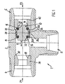
- a shuttle valve 1 consists of a Valve housing 2 with two inlets 4 and 6 and an outlet 8 and from one inside the valve housing 2 in such a way by pressure differences between the Inlets 4 and 6 movably guided valve element 10 that the outlet 8 automatically connected to the inlet 4 or 6, each carrying a higher pressure P1 or P2 and at the same time the other inlet 6 or 4 is blocked off.
- FIG. 1 shows a situation in which the pressure P1 at the first inlet 4 is higher than the pressure P2 is at the other, second inlet 6.
- the valve element 10 automatically moves into its sealing position to shut off the second inlet 6, whereby the first inlet 4 is connected to the outlet 8. If now in one Operating state of pressure P2 should exceed pressure P1, this switches Shuttle valve 1 around by the valve element 10 in its other sealing position moves to shut off the first inlet 4 and connect the second Inlet 6 with the outlet 8.
- the longitudinal movement of the valve element 10 is shown in FIG. 1 illustrated with a double arrow 12.
- the valve housing 2 is essentially T-shaped, the Inlets 4.6 corresponding to the T-crossbar and the outlet 8 corresponding to the T-longitudinal web are aligned and the valve element 10 in the direction of the T-crosspiece is reciprocable.
- the valve element 10 is essentially piston-like cylindrical body with two opposing soft seals 14 and 16 trained. Each of these soft seals 14, 16 acts in the respective one Sealing position of the valve element 10 with one of two inlet-side valve seat surfaces 18 or 20 together. These valve seat surfaces 18, 20 are preferred as Inner cone surfaces executed. Each soft seal 14, 16 is expedient by an elastic seated in an annular groove 22 or 24 of the valve element 10 Sealing ring (O-ring) formed.
- the valve element 10 carries a Seal protection sleeve 26.
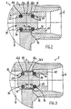
- This seal protection sleeve 26 is on the piston-like Body of the valve element 10 guided such that in each of the two Sealing positions of the valve element 10, the inlet to be shut off (in the position shown inlet 6) facing soft seal (16) for contact with the associated valve seat surface (20) released and the other, opposite Soft seal (14) is covered by the seal protection sleeve 26.
- the seal protection sleeve 26 is thus relative to the piston-like body of the valve element 10 axially movable, which in Fig.
- Seal protection sleeve 26 each with one of two within the valve housing 2 formed stop surfaces 30 and 32 together. Furthermore, the Seal protection sleeve 26 has a central guide section 26a and two end-side, mutually opposite overlap sections 26b for radial and axial Cover the respective soft seal 14 or 16.
- the guide section has 26a of the seal protection sleeve 26 has a radially inwardly projecting annular web shoulder 26d, which engages radially in an annular groove 10b of the valve element 10.
- the Ring web insert 26d within the annular groove 10b axially between two defined Stop positions movable.
- the defined stop positions between the sealing sleeve 26 and the Valve element 10 any load on the soft seals 14, 16 by contacting the Seal protection sleeve 26 avoided.
- valve element 10 in adaptation to the inner conical valve seat surfaces 18, 20 - outer conical end sections 34, 36 on, in the respective sealing position flat in the respective valve seat surface 18, 20 intervention.
- the main advantages of these conical contact surfaces are absolute Gap-free, avoidance of seal extrusion and high pressure resistance.
- valve seat surfaces 18, 20 are each part of are valve bushings 38, 40 inserted into the valve housing 2.
- valve bushing 38, 40 also has the respective one with a radial end face Stop surface 30 or 32 for the protective seal sleeve 26.
- the invention is not limited to that shown and described Embodiments limited, but also includes all within the meaning of the invention equivalent designs. Furthermore, the invention is not yet open the combination of features defined in claim 1 limits, but can also through any other combination of certain characteristics of all overall disclosed individual features can be defined. This means that basically omitted practically every single feature of claim 1 or by at least one individual feature disclosed elsewhere in the application can be replaced. In this respect, claim 1 is only a first To understand formulation attempt for an invention.
Landscapes
- Engineering & Computer Science (AREA)
- General Engineering & Computer Science (AREA)
- Theoretical Computer Science (AREA)
- Physics & Mathematics (AREA)
- Fluid Mechanics (AREA)
- Mechanical Engineering (AREA)
- Multiple-Way Valves (AREA)
- Lift Valve (AREA)
- Pens And Brushes (AREA)
- Particle Formation And Scattering Control In Inkjet Printers (AREA)
Description
- Fig. 1
- ein erfindungsgemäßes Wechselventil im Längsschnitt (Schnitt in einer durch die Strömungswege verlaufenden Ebene) in einer ersten Ausführungsform,
- Fig. 2
- eine vergrößerte Teilansicht im Bereich des Ventilelementes in einer seiner beiden Dichtstellungen und
- Fig. 3
- eine Ansicht wie in Fig. 2, jedoch in einer Ausführungsvariante des Ventilelementes.
Claims (9)
- Selbstgesteuertes Wechselventil (1) für Druckmedien, mit einem Ventilgehäuse (2) mit zwei Einlässen (4, 6) und einem Auslaß (8) sowie mit einem innerhalb des Ventilgehäuses (2) derart durch Druckunterschiede zwischen den Einlässen (4, 6) beweglich geführten Ventilelement (10), dass der Auslaß (8) selbsttätig mit dem jeweils einen höheren Druck (P1/P2) führenden Einlaß (4 oder 6) verbunden und der jeweils andere Einlaß (6 oder 4) abgesperrt wird, wobei das Ventilelement (10) kolbenartig mit zwei einander gegenüberliegenden, mit einlaßseitigen Ventilsitzflächen (18, 20) zusammenwirkenden Weichdichtungen (14, 16) ausgebildet ist,
gekennzeichnet durch eine auf dem Ventilelement (10) derart verschiebbar geführte Dichtungsschutzhülse (26), dass in jeder der beiden Dichtstellungen des Ventilelementes (10) die dem jeweils abzusperrenden Einlaß (4 oder 6) zugekehrte Weichdichtung (14 oder 16) zur Anlage an der zugehörigen Ventilsitzfläche (18 oder 20) freigegeben und die andere, gegenüberliegende Weichdichtung (16 oder 14) von der Dichtungsschutzhülse (26) überdeckt wird. - Wechselventil nach Anspruch 1,
dadurch gekennzeichnet, dass jede Weichdichtung (14,16) durch einen in einer Ringnut (22, 24) des Ventilelementes (10) sitzenden elastischen Dichtring gebildet ist. - Wechselventil nach Anspruch 1 oder 2,
dadurch gekennzeichnet, dass die Dichtungsschutzhülse (26) für ihre relative Verschiebung auf dem Ventilelement (10) mit Anschlagflächen (30, 32) innerhalb des Ventilgehäuses (2) zusammenwirkt. - Wechselventil nach einem der Ansprüche 1 bis 3,
dadurch gekennzeichnet, dass die Dichtungsschutzhülse (26) einen mittigen Führungsabschnitt (26a) und zwei endseitige, gegenüberliegende Überdeckungsabschnitte (26 b) zum radialen und axialen Überdecken der jeweiligen Weichdichtung (14, 16) aufweist. - Wechselventil nach Anspruch 4,
dadurch gekennzeichnet, dass der Führungsabschnitt (26a) mit einer zylindrischen Innenfläche (26 c) axial verschiebbar auf einer entsprechend zylindrischen Außenfläche (10 a) des Ventilelementes (10) geführt ist. - Wechselventil nach Anspruch 4,
dadurch gekennzeichnet, dass der Führungsabschnitt (26a) mit einem inneren Ringstegansatz (26 d) radial in eine Ringnut (10 b) des Ventilelementes (10) eingreift, wobei der Ringstegansatz (26 d) innerhalb der Ringnut (10 b) axial zwischen zwei definierten Anschlagstellungen beweglich ist. - Wechselventil nach einem der Ansprüche 1 bis 6,
dadurch gekennzeichnet, dass das kolbenartige Ventilelement 10) außenkonische Endabschnitte (34, 36) aufweist, die in der jeweiligen Dichtstellung in die jeweilige, entsprechend innenkonisch ausgebildete Ventilsitzfläche (18, 20) eingreifen. - Wechselventil nach einem der Ansprüche 1 bis 7,
dadurch gekennzeichnet, dass das Ventilgehäuse (2) im Wesentlichen T-förmig ausgebildet ist, wobei die Einlässe (4, 6) entsprechend dem T-Quersteg und der Auslaß (8) entsprechend dem T-Längssteg ausgerichtet sind und das Ventilelement (10) in Richtung des T-Quersteges hinund herbeweglich ist. - Wechselventil nach einem der Ansprüche 1 bis 8,
dadurch gekennzeichnet, dass die Ventilsitzflächen (18, 20) jeweils Teil von in das Ventilgehäuse (2) eingesetzten Ventilbuchsen (38, 40) sind, wobei vorzugsweise jede Ventilbuchse (38, 40) auch mit einer radialen Stirnfläche die jeweilige Anschlagfläche (30, 32) für die Dichtungsschutzhülse (26) bildet.
Applications Claiming Priority (2)
| Application Number | Priority Date | Filing Date | Title |
|---|---|---|---|
| DE20016538U DE20016538U1 (de) | 2000-09-25 | 2000-09-25 | Wechselventil für Druckmedien |
| DE20016538U | 2000-09-25 |
Publications (3)
| Publication Number | Publication Date |
|---|---|
| EP1191235A2 EP1191235A2 (de) | 2002-03-27 |
| EP1191235A3 EP1191235A3 (de) | 2003-11-05 |
| EP1191235B1 true EP1191235B1 (de) | 2004-12-08 |
Family
ID=7946904
Family Applications (1)
| Application Number | Title | Priority Date | Filing Date |
|---|---|---|---|
| EP01122527A Expired - Lifetime EP1191235B1 (de) | 2000-09-25 | 2001-09-24 | Wechselventil für Druckmedien |
Country Status (4)
| Country | Link |
|---|---|
| EP (1) | EP1191235B1 (de) |
| AT (1) | ATE284489T1 (de) |
| DE (2) | DE20016538U1 (de) |
| ES (1) | ES2228720T3 (de) |
Families Citing this family (3)
| Publication number | Priority date | Publication date | Assignee | Title |
|---|---|---|---|---|
| DE20315718U1 (de) * | 2003-10-13 | 2004-11-25 | Schmitz Cargobull Ag | Wechselventil für eine Druckluft-Bremsanlage |
| DE102009007677A1 (de) * | 2009-02-05 | 2010-08-19 | Knorr-Bremse Systeme für Nutzfahrzeuge GmbH | Kolbenventil, insbesondere für eine pneumatische Bremsanlage eines Fahrzeugs |
| CN102889398B (zh) * | 2012-10-12 | 2014-04-30 | 常德中联重科液压有限公司 | 梭阀、梭阀驱动式装置、卷筒制动缸控制回路及起重机 |
Family Cites Families (5)
| Publication number | Priority date | Publication date | Assignee | Title |
|---|---|---|---|---|
| US2354791A (en) * | 1943-02-05 | 1944-08-01 | Wagner Electric Corp | Two-way valve mechanism |
| GB685203A (en) * | 1949-01-11 | 1952-12-31 | Electro Hydraulics Ltd | Improvements in or relating to fluid control valves, and pipe couplings therefor |
| US2900166A (en) * | 1950-11-24 | 1959-08-18 | Parker Hannifin Corp | Shuttle valve |
| US3338257A (en) * | 1964-05-22 | 1967-08-29 | Westinghouse Air Brake Co | Double check valve |
| DE8613517U1 (de) * | 1986-05-17 | 1992-10-08 | GOK Regler- und Armaturen GmbH & Co KG, 53721 Siegburg | Wechselventil für 2 Sicherheitsventile |
-
2000
- 2000-09-25 DE DE20016538U patent/DE20016538U1/de not_active Expired - Lifetime
-
2001
- 2001-09-24 EP EP01122527A patent/EP1191235B1/de not_active Expired - Lifetime
- 2001-09-24 ES ES01122527T patent/ES2228720T3/es not_active Expired - Lifetime
- 2001-09-24 DE DE2001504748 patent/DE50104748D1/de not_active Expired - Lifetime
- 2001-09-24 AT AT01122527T patent/ATE284489T1/de active
Also Published As
| Publication number | Publication date |
|---|---|
| DE50104748D1 (de) | 2005-01-13 |
| EP1191235A2 (de) | 2002-03-27 |
| DE20016538U1 (de) | 2002-02-14 |
| ATE284489T1 (de) | 2004-12-15 |
| EP1191235A3 (de) | 2003-11-05 |
| ES2228720T3 (es) | 2005-04-16 |
Similar Documents
| Publication | Publication Date | Title |
|---|---|---|
| DE3721558C2 (de) | Endverschluß für einen Fluidzylinder | |
| DE3700536A1 (de) | Absperrschieber | |
| DE4342378A1 (de) | Absperrschieber | |
| DE2160467A1 (de) | Schieber ventil | |
| DE3413698C2 (de) | ||
| DE102009024899B4 (de) | Hydraulische Kupplung mit Tellerventil mit glatter Bohrung | |
| DE19837694B4 (de) | Coaxialventil mit Gegendruckrückentlastung | |
| DE3151567C2 (de) | Abblase- und Rückschlagventil | |
| DE2424978A1 (de) | Rohrunterbrecher, insbesondere fuer hauswasserleitungen | |
| EP0832382B1 (de) | Trockenlaufdichtungsring | |
| DE2062292A1 (de) | Dichtung fur ein Durchfluß Steuerventil | |
| EP1191235B1 (de) | Wechselventil für Druckmedien | |
| DE112021000256B4 (de) | Vorrichtung zum halten eines schafts eines hydraulikzylinders in stellung und verfahren zum entsperren und absperren eines sekundär-rückschlagventils der vorrichtung | |
| DE19544901C2 (de) | Absperrvorrichtung für eine Fluidleitung, insbesondere Kugelhahn | |
| EP0068251B1 (de) | Umschaltventil für Verbundzähler | |
| DE3107012C2 (de) | ||
| DE19723962C2 (de) | Doppelplattenschieber | |
| EP0887559B1 (de) | Mehrwegeventil | |
| WO2023169669A1 (de) | Drehschieberventil eines kraftfahrzeug-kühlkreislaufs | |
| DE2626668C2 (de) | Rohr- oder Schlauchleitungskupplung | |
| DE2915432A1 (de) | Ventilstellglied | |
| DE2313937C3 (de) | Absperreinrichtung für Tiefbohrungen | |
| DE102008051624B4 (de) | Schieberventil | |
| DE3502588A1 (de) | Umschaltventil | |
| DE10111332B4 (de) | Kolbenspeicher |
Legal Events
| Date | Code | Title | Description |
|---|---|---|---|
| PUAI | Public reference made under article 153(3) epc to a published international application that has entered the european phase |
Free format text: ORIGINAL CODE: 0009012 |
|
| AK | Designated contracting states |
Kind code of ref document: A2 Designated state(s): AT BE CH CY DE DK ES FI FR GB GR IE IT LI LU MC NL PT SE TR |
|
| AX | Request for extension of the european patent |
Free format text: AL;LT;LV;MK;RO;SI |
|
| PUAL | Search report despatched |
Free format text: ORIGINAL CODE: 0009013 |
|
| AK | Designated contracting states |
Kind code of ref document: A3 Designated state(s): AT BE CH CY DE DK ES FI FR GB GR IE IT LI LU MC NL PT SE TR |
|
| AX | Request for extension of the european patent |
Extension state: AL LT LV MK RO SI |
|
| RAP1 | Party data changed (applicant data changed or rights of an application transferred) |
Owner name: VOSS FLUID GMBH & CO. KG |
|
| GRAP | Despatch of communication of intention to grant a patent |
Free format text: ORIGINAL CODE: EPIDOSNIGR1 |
|
| 17P | Request for examination filed |
Effective date: 20040430 |
|
| AKX | Designation fees paid |
Designated state(s): AT BE CH CY DE DK ES FI FR GB GR IE IT LI LU MC NL PT SE TR |
|
| GRAS | Grant fee paid |
Free format text: ORIGINAL CODE: EPIDOSNIGR3 |
|
| GRAA | (expected) grant |
Free format text: ORIGINAL CODE: 0009210 |
|
| AK | Designated contracting states |
Kind code of ref document: B1 Designated state(s): AT BE CH CY DE DK ES FI FR GB GR IE IT LI LU MC NL PT SE TR |
|
| PG25 | Lapsed in a contracting state [announced via postgrant information from national office to epo] |
Ref country code: FI Free format text: LAPSE BECAUSE OF FAILURE TO SUBMIT A TRANSLATION OF THE DESCRIPTION OR TO PAY THE FEE WITHIN THE PRESCRIBED TIME-LIMIT Effective date: 20041208 Ref country code: TR Free format text: LAPSE BECAUSE OF FAILURE TO SUBMIT A TRANSLATION OF THE DESCRIPTION OR TO PAY THE FEE WITHIN THE PRESCRIBED TIME-LIMIT Effective date: 20041208 Ref country code: IE Free format text: LAPSE BECAUSE OF FAILURE TO SUBMIT A TRANSLATION OF THE DESCRIPTION OR TO PAY THE FEE WITHIN THE PRESCRIBED TIME-LIMIT Effective date: 20041208 |
|
| REG | Reference to a national code |
Ref country code: GB Ref legal event code: FG4D Free format text: NOT ENGLISH |
|
| REG | Reference to a national code |
Ref country code: CH Ref legal event code: EP Ref country code: CH Ref legal event code: NV Representative=s name: TROESCH SCHEIDEGGER WERNER AG |
|
| REG | Reference to a national code |
Ref country code: IE Ref legal event code: FG4D Free format text: GERMAN |
|
| REF | Corresponds to: |
Ref document number: 50104748 Country of ref document: DE Date of ref document: 20050113 Kind code of ref document: P |
|
| GBT | Gb: translation of ep patent filed (gb section 77(6)(a)/1977) |
Effective date: 20050207 |
|
| PG25 | Lapsed in a contracting state [announced via postgrant information from national office to epo] |
Ref country code: GR Free format text: LAPSE BECAUSE OF FAILURE TO SUBMIT A TRANSLATION OF THE DESCRIPTION OR TO PAY THE FEE WITHIN THE PRESCRIBED TIME-LIMIT Effective date: 20050308 Ref country code: DK Free format text: LAPSE BECAUSE OF FAILURE TO SUBMIT A TRANSLATION OF THE DESCRIPTION OR TO PAY THE FEE WITHIN THE PRESCRIBED TIME-LIMIT Effective date: 20050308 Ref country code: SE Free format text: LAPSE BECAUSE OF FAILURE TO SUBMIT A TRANSLATION OF THE DESCRIPTION OR TO PAY THE FEE WITHIN THE PRESCRIBED TIME-LIMIT Effective date: 20050308 |
|
| REG | Reference to a national code |
Ref country code: ES Ref legal event code: FG2A Ref document number: 2228720 Country of ref document: ES Kind code of ref document: T3 |
|
| REG | Reference to a national code |
Ref country code: IE Ref legal event code: FD4D |
|
| ET | Fr: translation filed | ||
| PG25 | Lapsed in a contracting state [announced via postgrant information from national office to epo] |
Ref country code: CY Free format text: LAPSE BECAUSE OF FAILURE TO SUBMIT A TRANSLATION OF THE DESCRIPTION OR TO PAY THE FEE WITHIN THE PRESCRIBED TIME-LIMIT Effective date: 20050924 |
|
| PG25 | Lapsed in a contracting state [announced via postgrant information from national office to epo] |
Ref country code: MC Free format text: LAPSE BECAUSE OF NON-PAYMENT OF DUE FEES Effective date: 20050930 Ref country code: LU Free format text: LAPSE BECAUSE OF NON-PAYMENT OF DUE FEES Effective date: 20050930 Ref country code: BE Free format text: LAPSE BECAUSE OF NON-PAYMENT OF DUE FEES Effective date: 20050930 |
|
| PLBE | No opposition filed within time limit |
Free format text: ORIGINAL CODE: 0009261 |
|
| STAA | Information on the status of an ep patent application or granted ep patent |
Free format text: STATUS: NO OPPOSITION FILED WITHIN TIME LIMIT |
|
| 26N | No opposition filed |
Effective date: 20050909 |
|
| BERE | Be: lapsed |
Owner name: *VOSS FLUID G.M.B.H. & CO. K.G. Effective date: 20050930 |
|
| PG25 | Lapsed in a contracting state [announced via postgrant information from national office to epo] |
Ref country code: PT Free format text: LAPSE BECAUSE OF NON-PAYMENT OF DUE FEES Effective date: 20050508 |
|
| REG | Reference to a national code |
Ref country code: CH Ref legal event code: PFA Owner name: VOSS FLUID GMBH Free format text: VOSS FLUID GMBH & CO. KG#LUEDENSCHEIDER STRASSE 52-54#51688 WIPPERFUERTH (DE) -TRANSFER TO- VOSS FLUID GMBH#LUEDENSCHEIDER STRASSE 52-54#51688 WIPPERFUERTH (DE) |
|
| REG | Reference to a national code |
Ref country code: ES Ref legal event code: PC2A |
|
| NLT1 | Nl: modifications of names registered in virtue of documents presented to the patent office pursuant to art. 16 a, paragraph 1 |
Owner name: VOSS FLUID GMBH |
|
| REG | Reference to a national code |
Ref country code: FR Ref legal event code: CJ |
|
| PGFP | Annual fee paid to national office [announced via postgrant information from national office to epo] |
Ref country code: ES Payment date: 20080911 Year of fee payment: 8 |
|
| PGFP | Annual fee paid to national office [announced via postgrant information from national office to epo] |
Ref country code: FR Payment date: 20080915 Year of fee payment: 8 Ref country code: IT Payment date: 20080924 Year of fee payment: 8 |
|
| PGFP | Annual fee paid to national office [announced via postgrant information from national office to epo] |
Ref country code: GB Payment date: 20080924 Year of fee payment: 8 |
|
| PGFP | Annual fee paid to national office [announced via postgrant information from national office to epo] |
Ref country code: CH Payment date: 20081016 Year of fee payment: 8 |
|
| REG | Reference to a national code |
Ref country code: CH Ref legal event code: PL |
|
| GBPC | Gb: european patent ceased through non-payment of renewal fee |
Effective date: 20090924 |
|
| REG | Reference to a national code |
Ref country code: FR Ref legal event code: ST Effective date: 20100531 |
|
| PG25 | Lapsed in a contracting state [announced via postgrant information from national office to epo] |
Ref country code: FR Free format text: LAPSE BECAUSE OF NON-PAYMENT OF DUE FEES Effective date: 20090930 |
|
| PG25 | Lapsed in a contracting state [announced via postgrant information from national office to epo] |
Ref country code: CH Free format text: LAPSE BECAUSE OF NON-PAYMENT OF DUE FEES Effective date: 20090930 Ref country code: LI Free format text: LAPSE BECAUSE OF NON-PAYMENT OF DUE FEES Effective date: 20090930 |
|
| PG25 | Lapsed in a contracting state [announced via postgrant information from national office to epo] |
Ref country code: GB Free format text: LAPSE BECAUSE OF NON-PAYMENT OF DUE FEES Effective date: 20090924 |
|
| PGFP | Annual fee paid to national office [announced via postgrant information from national office to epo] |
Ref country code: DE Payment date: 20101126 Year of fee payment: 10 |
|
| PG25 | Lapsed in a contracting state [announced via postgrant information from national office to epo] |
Ref country code: IT Free format text: LAPSE BECAUSE OF NON-PAYMENT OF DUE FEES Effective date: 20090924 |
|
| REG | Reference to a national code |
Ref country code: ES Ref legal event code: FD2A Effective date: 20110714 |
|
| PG25 | Lapsed in a contracting state [announced via postgrant information from national office to epo] |
Ref country code: ES Free format text: LAPSE BECAUSE OF NON-PAYMENT OF DUE FEES Effective date: 20110704 |
|
| PG25 | Lapsed in a contracting state [announced via postgrant information from national office to epo] |
Ref country code: ES Free format text: LAPSE BECAUSE OF NON-PAYMENT OF DUE FEES Effective date: 20090925 |
|
| PGFP | Annual fee paid to national office [announced via postgrant information from national office to epo] |
Ref country code: AT Payment date: 20110826 Year of fee payment: 11 |
|
| PGFP | Annual fee paid to national office [announced via postgrant information from national office to epo] |
Ref country code: NL Payment date: 20110922 Year of fee payment: 11 |
|
| REG | Reference to a national code |
Ref country code: NL Ref legal event code: V1 Effective date: 20130401 |
|
| REG | Reference to a national code |
Ref country code: AT Ref legal event code: MM01 Ref document number: 284489 Country of ref document: AT Kind code of ref document: T Effective date: 20120924 |
|
| REG | Reference to a national code |
Ref country code: DE Ref legal event code: R119 Ref document number: 50104748 Country of ref document: DE Effective date: 20130403 |
|
| PG25 | Lapsed in a contracting state [announced via postgrant information from national office to epo] |
Ref country code: DE Free format text: LAPSE BECAUSE OF NON-PAYMENT OF DUE FEES Effective date: 20130403 Ref country code: AT Free format text: LAPSE BECAUSE OF NON-PAYMENT OF DUE FEES Effective date: 20120924 |
|
| PG25 | Lapsed in a contracting state [announced via postgrant information from national office to epo] |
Ref country code: NL Free format text: LAPSE BECAUSE OF NON-PAYMENT OF DUE FEES Effective date: 20130401 |