EP1190934B1 - Ensemble de direction volant, coussin central, coquille d'habillage et véhicule automobile correspondants - Google Patents
Ensemble de direction volant, coussin central, coquille d'habillage et véhicule automobile correspondants Download PDFInfo
- Publication number
- EP1190934B1 EP1190934B1 EP01402433A EP01402433A EP1190934B1 EP 1190934 B1 EP1190934 B1 EP 1190934B1 EP 01402433 A EP01402433 A EP 01402433A EP 01402433 A EP01402433 A EP 01402433A EP 1190934 B1 EP1190934 B1 EP 1190934B1
- Authority
- EP
- European Patent Office
- Prior art keywords
- steering
- steering wheel
- branch
- central
- unit
- Prior art date
- Legal status (The legal status is an assumption and is not a legal conclusion. Google has not performed a legal analysis and makes no representation as to the accuracy of the status listed.)
- Expired - Lifetime
Links
Images


Classifications
-
- B—PERFORMING OPERATIONS; TRANSPORTING
- B62—LAND VEHICLES FOR TRAVELLING OTHERWISE THAN ON RAILS
- B62D—MOTOR VEHICLES; TRAILERS
- B62D1/00—Steering controls, i.e. means for initiating a change of direction of the vehicle
- B62D1/02—Steering controls, i.e. means for initiating a change of direction of the vehicle vehicle-mounted
- B62D1/04—Hand wheels
- B62D1/10—Hubs; Connecting hubs to steering columns, e.g. adjustable
- B62D1/105—Non-rotatable hubs, e.g. the central part of the steering wheel not rotating
-
- Y—GENERAL TAGGING OF NEW TECHNOLOGICAL DEVELOPMENTS; GENERAL TAGGING OF CROSS-SECTIONAL TECHNOLOGIES SPANNING OVER SEVERAL SECTIONS OF THE IPC; TECHNICAL SUBJECTS COVERED BY FORMER USPC CROSS-REFERENCE ART COLLECTIONS [XRACs] AND DIGESTS
- Y10—TECHNICAL SUBJECTS COVERED BY FORMER USPC
- Y10T—TECHNICAL SUBJECTS COVERED BY FORMER US CLASSIFICATION
- Y10T74/00—Machine element or mechanism
- Y10T74/20—Control lever and linkage systems
- Y10T74/20576—Elements
- Y10T74/20732—Handles
- Y10T74/20834—Hand wheels
Definitions
- the present invention relates to a steering assembly for motor vehicle according to the preamble of claim 1.
- Such an assembly allows a rotational drive of the shaft steering wheel while keeping the central cushion fixed.
- Such a central cushion generally includes several accessories, including a safety air bag module, a safety switch horn control and other control devices different functional equipment of the vehicle.
- a set according to the preamble of claim 1 is known for example from document EP-825 089.
- the connection between the rear end of the steering shaft and the second ends of the steering wheel arms is secured by screws.
- Each branch extends from its second end axially towards rearward and radially outward, substantially forming an arc of circle.
- the front face of the central cushion opposite the branches has a profile corresponding.
- the steering assembly further includes a shell covering disposed in front of the steering wheel to hide the rear end of the steering column. This covering shell has a rear face which is opposite the second ends of the branches and which is substantially flat and transverse to the longitudinal axis.
- FR-A-1 150 606 describes a steering assembly with cushion central.
- the steering wheel temples include slight backtracking.
- the connection between the branches of the steering wheel and the steering shaft is visible from the lateral sides of the assembly direction.
- US-A-4,711,650 discloses a cushioned steering assembly fixed central. The link between the steering wheel and the steering shaft is visible laterally.
- An object of the invention is to improve the aesthetic appearance of a assembly according to the preamble of claim 1 by limiting the possibilities that an observer has to see, from outside the assembly, the connection between the steering wheel and the rear end of the steering shaft.
- the invention relates to an assembly according to the claim 1.
- the set may include the features of the dependent claims.
- the invention also relates to a motor vehicle according to claim 5.
- orientations used are the usual orientations of a motor vehicle.
- the terms "before” and “Rear” therefore means in relation to the position of a driver.
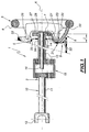
- FIG. 1 shows a steering assembly 1 of a vehicle automobile.
- This assembly 1 has a longitudinal axis A and includes a steering column 2, a steering wheel 3, a fixed central cushion 4 and a covering shell 5.
- the steering wheel 3, the cushion 4 and the covering shell 5 are mounted at the rear of the steering column 2.
- the steering wheel 3 includes an outer annular rim 6, a hub central 7 in the form of a disc and branches 8 connecting the hub 7 to the rim 6.
- the branches 8 are two in number.
- the fixed central cushion 4 conventionally comprises a safety air bag module not shown, or airbag, and possibly a horn control switch as well as other controls for different functional equipment in the vehicle.
- the covering shell 5 is a sheath open at its end front and closed at its rear end by a rear face 9.
- the shell 5 receives by its open front end the rear end of the column direction 2 in order to hide it.
- the front end of the covering shell 5 is received in an opening in the dashboard (not shown) of the motor vehicle.
- the steering column 2 includes a steering shaft 10 rotatable around the longitudinal axis A.
- the steering shaft 10 itself comprises a front section 11 provided at its front end with a fork gimbal 12 connected to the rest of the steering mechanism integrating the assembly 1, and a rear section 13 at the rear end 14 of which the steering wheel 3 is mounted thanks to its hub 7.
- This mounting can be provided for example at screw means passing through holes in the hub 7.
- the section rear 13 of the steering shaft 10 crosses the rear end of the shell dressing 5.
- the steering column 2 further comprises a device for gears 15 disposed between the front 11 and rear 13 sections of the shaft steering 10, and a fixed support 16 disposed inside the rear section 13 of the steering shaft 10 and at the rear of which the central cushion 4 is mounted.
- this mounting can be provided for example by means quote.
- Steering assembly 1 is a fixed center cushion assembly which, thanks to the gear device 15 and the fixed support 16, makes it possible to transmit to the front section 11 of the steering shaft 10 a movement of rotation of the rear section 13 produced by the steering wheel 3, while the central cushion 4 remains fixed.
- FIG. 1 the assembly 1 represented in FIG. 1 is similar to that described in document EP-825 089 where further information can be found. It should be noted that many other types of steering sets with a fixed central cushion are known and can . therefore be used in the context of the invention.
- each branch 8 which is connected by a first end 20 to the rim 6 and by a second end 21 to the central hub 7, has an axial cusp 22, oriented towards the rear, and located in the vicinity of the second end 21.
- the axial length of this cusp that is to say the length l separating the bottom 23 of the cusp 22 of the second end 21 of the branch 8 considered is approximately 30 mm and preferably greater than 15 mm.
- the front face 25 of the fixed central cushion 4, which is opposite the central hub 7 and branches 8 of the steering wheel 3, includes an axial skirt 26 annular, centered on axis A and projecting forward.
- This skirt 26 defines in the front face 25 a circular cavity 27 which extends axially towards the front and which is substantially centered on the axis A.
- the cavity 27 has a axial depth of about 25 mm and preferably more than 10 mm.
- This cavity 27 receives the central hub 7 and the second ends 21 of the branches 8 of the steering wheel 3.
- the hub 7 is disposed near the bottom 28 of the cavity 27 and the skirt 26 extends axially inside the cusp 22 practically to its bottom 23.
- the front face 25 of the fixed central cushion 4 therefore marries substantially the profile of the branches 8 in the vicinity of their ends 21 and of their cusps 22.
- a groove 31 oriented towards the rear is formed in the face rear 9 of the covering shell 5.
- This groove 31 is substantially revolution around the axis A and delimits an inner annular rim 32 and a outer rim 33 which protrudes rearward.
- the outer edge 33 is substantially annular in shape flattened on its lower sections and superior.
- the axial depth of the groove 31, that is to say between its bottom and the rim 33 is greater than 10 mm and preferably greater than 5 mm.
- a circular orifice 34 is formed in the center of the rear face 9. This orifice is bordered by the inner rim 32 and receives the section with little play rear 13 of the steering shaft 10 to allow it to rotate around its longitudinal axis A.
- the rim 32 is disposed in the cavity 27 of the central cushion fixed 4, axially behind the front end of the skirt 26.
- the groove 31 receives the funds 23 from the cusps 22 of the branches 8.
- the outer rim 33 is located axially behind the front end of the front skirt 26 of the central cushion 4.
- the rear face 9 of the shell 5 marries substantially the profile of the branches 8-in the vicinity of their ends 21 and of their cusps 22.
- the masking effect can also be obtained without using a covering shell 5 having a groove 31, if the arrangement inside the passenger compartment in the vicinity of the steering wheel 3 and the central cushion 4 is such that an occupant of the vehicle cannot be placed in front of the skirt 26 of the central cushion 4 to come and look back in the cavity 27 of the central cushion 4.
Landscapes
- Engineering & Computer Science (AREA)
- Chemical & Material Sciences (AREA)
- Combustion & Propulsion (AREA)
- Transportation (AREA)
- Mechanical Engineering (AREA)
- Steering Controls (AREA)
- Air Bags (AREA)
Description
- La figure 1 est une vue partielle, schématique, latérale et partiellement en coupe d'un ensemble de direction selon l'invention,
- la figure 2 est une vue schématique en perspective du volant, du coussin central fixe et de la coquille d'habillage de l'ensemble de direction de la figure 1,
- la figure 3 est une vue schématique en perspective du volant et du coussin central fixe de l'ensemble de direction de la figure 1, et
- la figure 4 est une vue schématique en perspective de la coquille d'habillage de l'ensemble de direction de la figure 1.
Claims (5)
- Ensemble de direction (1) pour véhicule automobile comprenant :une colonne de direction (2) comprenant un arbre de direction (10) susceptible de tourner autour d'un axe longitudinal (A),un volant (3) comprenant une jante extérieure (6) et au moins une branche (8) reliée par une première extrémité (20) à la jante et par une deuxième extrémité (21) à l'extrémité arrière (14) de l'arbre de direction pour l'entraíner en rotation autour de son axe longitudinal (A),un coussin central fixe (4) placé sensiblement au centre du volant à l'arrière de la deuxième extrémité de la ou de chaque branche et relié à l'extrémité arrière de la colonne de direction pour être fixe en rotation lorsque l'arbre de direction (10) tourne, caractérisé en ce que la ou chaque branche comprend un rebroussement axial (22) vers l'arrière et le coussin central (4) comprend une jupe axiale avant sensiblement annulaire qui délimite une cavité centrale (27), la jupe (26) s'étendant axialement à l'intérieur du ou de chaque rebroussement (22) et la cavité centrale (27) recevant la deuxième extrémité (21) de la ou de chaque branche de manière à masquer la liaison entre le volant (3) et l'arbre de direction (10).
- Ensemble selon la revendication 1, caractérisé en ce que le rebroussement (22) de la ou de chaque branche (8) a une longueur axiale (l) entre son fond et son extrémité radialement intérieure supérieure à environ 15 mm et la cavité centrale (27) a une profondeur axiale supérieure à environ 10 mm.
- Ensemble selon la revendication 1 ou 2, caractérisé en ce qu'il comprend en outre une coquille d'habillage (5) placée à l'avant de la deuxième extrémité (21) de la ou de chaque branche pour masquer l'extrémité arrière de la colonne de direction (2), et en ce qu'une gorge arrière (31) sensiblement annulaire est ménagée dans la coquille (5) et le ou chaque rebroussement est reçu dans la gorge (31 ).
- Ensemble selon l'une des revendications précédentes, caractérisé en ce que la gorge a une profondeur axiale supérieure à environ 5 mm.
- Véhicule automobile, caractérisé en ce qu'il comprend un ensemble de direction selon l'une des revendications précédentes.
Applications Claiming Priority (2)
| Application Number | Priority Date | Filing Date | Title |
|---|---|---|---|
| FR0012115 | 2000-09-22 | ||
| FR0012115A FR2814422B1 (fr) | 2000-09-22 | 2000-09-22 | Ensemble de direction volant, coussin central, coquille d'habillage et vehicule automobile correspondants |
Publications (2)
| Publication Number | Publication Date |
|---|---|
| EP1190934A1 EP1190934A1 (fr) | 2002-03-27 |
| EP1190934B1 true EP1190934B1 (fr) | 2003-12-03 |
Family
ID=8854595
Family Applications (1)
| Application Number | Title | Priority Date | Filing Date |
|---|---|---|---|
| EP01402433A Expired - Lifetime EP1190934B1 (fr) | 2000-09-22 | 2001-09-21 | Ensemble de direction volant, coussin central, coquille d'habillage et véhicule automobile correspondants |
Country Status (5)
| Country | Link |
|---|---|
| US (1) | US20020035888A1 (fr) |
| EP (1) | EP1190934B1 (fr) |
| DE (1) | DE60101356T2 (fr) |
| ES (1) | ES2210108T3 (fr) |
| FR (1) | FR2814422B1 (fr) |
Families Citing this family (2)
| Publication number | Priority date | Publication date | Assignee | Title |
|---|---|---|---|---|
| DE102014207382A1 (de) * | 2014-04-17 | 2015-10-22 | Bayerische Motoren Werke Aktiengesellschaft | Lenkradanordnung für ein Fahrzeug |
| ITBO20140081U1 (it) * | 2014-09-30 | 2016-03-30 | I F R A S R L | Un organo per il controllo della direzione di un veicolo, in particolare di un veicolo nautico. |
Family Cites Families (24)
| Publication number | Priority date | Publication date | Assignee | Title |
|---|---|---|---|---|
| US1246244A (en) * | 1917-06-11 | 1917-11-13 | Security Auto Lock Company | Steering-wheel for motor-vehicles. |
| US1494516A (en) * | 1922-09-07 | 1924-05-20 | Steering wheel | |
| US1784733A (en) * | 1929-10-12 | 1930-12-09 | H A Husted Company | Steering wheel |
| US2210232A (en) * | 1939-07-25 | 1940-08-06 | Guy S Crockett | Safety steering wheel |
| US2685214A (en) * | 1952-04-14 | 1954-08-03 | Robert K Maud | Steering wheel |
| FR1150606A (fr) * | 1956-05-16 | 1958-01-16 | Simca Automobiles Sa | Volant de direction de sécurité |
| DE1229860B (de) * | 1960-11-11 | 1966-12-01 | Daimler Benz Ag | Sicherheitslenkrad |
| GB1143688A (fr) * | 1966-12-09 | |||
| US3540304A (en) * | 1966-12-31 | 1970-11-17 | Daimler Benz Ag | Safety steering for motor vehicles |
| DE1755247B2 (de) * | 1968-04-18 | 1978-02-09 | Daimler-Benz Ag, 7000 Stuttgart | Sicherheitslenkrad fuer kraftwagen |
| DE2842020C2 (de) * | 1978-09-27 | 1986-03-13 | Bernd 5000 Köln Pilatzki | Lenkvorrichtung für Kraftfahrzeuge mit einem Pralltopf |
| DE3240875A1 (de) * | 1982-11-05 | 1984-05-10 | Bernd 5000 Köln Pilatzki | Lenkrad fuer kraftfahrzeuge |
| JPS6092652U (ja) * | 1983-12-01 | 1985-06-25 | 株式会社東海理化電機製作所 | ステアリング装置 |
| JPS60251415A (ja) * | 1984-05-28 | 1985-12-12 | Nissan Motor Co Ltd | ステアリング装置 |
| DE3621226C1 (de) * | 1986-06-25 | 1988-01-14 | Daimler Benz Ag | Lenkradanordnung fuer Fahrzeuge |
| DE3741130C1 (de) * | 1987-12-04 | 1989-05-11 | Daimler Benz Ag | Lenkung fuer Kraftwagen |
| US5072628A (en) * | 1989-09-19 | 1991-12-17 | Oki T Jack | Multi function steering mechanism for a motor vehicle |
| DE4105026C1 (fr) * | 1991-02-19 | 1992-02-20 | Mercedes-Benz Aktiengesellschaft, 7000 Stuttgart, De | |
| US5139281A (en) * | 1991-03-11 | 1992-08-18 | General Motors Corporation | Automotive steering column |
| DE4328563C1 (de) * | 1993-08-25 | 1994-08-25 | Daimler Benz Ag | Lenkradanordnung mit einer relativ zum Lenkrad stillstehenden Prallplatte |
| FR2720709B1 (fr) * | 1994-06-01 | 1996-07-12 | Rech Etudes Indles Civile | Module de commande pour mécanisme de direction d'un véhicule automobile. |
| FR2752552B1 (fr) * | 1996-08-20 | 1998-10-23 | Renault | Dispositif de commande de direction de vehicule automobile comportant un bloc de commandes agence au centre du volant |
| US6122992A (en) * | 1996-10-29 | 2000-09-26 | Trw Inc. | Steering wheel and air bag assembly attachment to a steering shaft |
| DE19838452C1 (de) * | 1998-08-25 | 2000-05-18 | Trw Automotive Safety Sys Gmbh | Lenkrad für ein Kraftfahrzeug und Verfahren zur Herstellung eines Lenkradkranzes |
-
2000
- 2000-09-22 FR FR0012115A patent/FR2814422B1/fr not_active Expired - Fee Related
-
2001
- 2001-09-21 ES ES01402433T patent/ES2210108T3/es not_active Expired - Lifetime
- 2001-09-21 US US09/956,824 patent/US20020035888A1/en not_active Abandoned
- 2001-09-21 EP EP01402433A patent/EP1190934B1/fr not_active Expired - Lifetime
- 2001-09-21 DE DE60101356T patent/DE60101356T2/de not_active Expired - Fee Related
Also Published As
| Publication number | Publication date |
|---|---|
| DE60101356D1 (de) | 2004-01-15 |
| US20020035888A1 (en) | 2002-03-28 |
| ES2210108T3 (es) | 2004-07-01 |
| FR2814422B1 (fr) | 2002-12-20 |
| DE60101356T2 (de) | 2004-12-09 |
| FR2814422A1 (fr) | 2002-03-29 |
| EP1190934A1 (fr) | 2002-03-27 |
Similar Documents
| Publication | Publication Date | Title |
|---|---|---|
| TWI409190B (zh) | 機車之後視鏡及機車 | |
| EP1885594B1 (fr) | Vehicule routier a habitacle pendulaire | |
| FR2750387A1 (fr) | Dispositif a element de commande pour commander le deplacement longitudinal et le deplacement transversal d'un vehicule automobile | |
| FR2668741A1 (fr) | Dispositif d'articulation pour sieges de vehicules, notamment pour sieges de vehicules automobiles. | |
| KR102649470B1 (ko) | 오토 스티어링 휠 고정용 브라켓 | |
| EP0489638B1 (fr) | Dispositif formant suspension notamment pour une roue directrice d'un véhicule automobile | |
| EP1073563B1 (fr) | Jambe de force d'une suspension de roue de type mac pherson | |
| JP2009190700A (ja) | 操舵装置 | |
| EP1190934A1 (fr) | Ensemble de direction volant, coussin central, coquille d'habillage et véhicule automobile correspondants | |
| EP1127729B1 (fr) | Agencement de planche de bord de véhicule automobile | |
| EP1169210B1 (fr) | Vehicule a pendularite variable guidee | |
| FR2682326A1 (fr) | Suspension notamment a bras tire pour vehicule automobile, avec systeme d'amortissement des chocs longitudinaux. | |
| EP2643169B1 (fr) | Element de liaison au sol d'un vehicule formant un corps creux et procede de fabrication d'un tel element de liaison au sol | |
| EP0520870B1 (fr) | Dispositif de suspension, notamment de suspension arrière multibras pour véhicule automobile | |
| FR2877303A1 (fr) | Dispositif de liaison entre la colonne de direction et la caisse d'un vehicule automobile. | |
| FR2692220A1 (fr) | Véhicule routier à disposition de roues perfectionnée. | |
| EP1743831B1 (fr) | Véhicule avec roue arrière directrice | |
| EP0289397B1 (fr) | Pare-chocs pour véhicule automobile et véhicule équipé d'un tel pare-chocs | |
| EP0915798A1 (fr) | Perfectionnement pour chassis de vehicule | |
| EP4696521A1 (fr) | Enjoliveur à positionnement précis contre un voile d'une roue d'un véhicule terrestre | |
| FR3141391A1 (fr) | Ensemble de planche de bord comprenant un dispositif d’affichage en porte-à-faux | |
| WO2025099367A1 (fr) | Pièce d'ornement pour planche de bord et ensemble comprenant une telle pièce d'ornement | |
| EP1468894B1 (fr) | Ensemble de direction à fréquence propre de vibration accrue et véhicule automobile correspondant | |
| FR3112834A1 (fr) | Roue dentée de réducteur de direction assistée renforcée, et système de direction assistée comprenant une telle roue dentée | |
| FR2736022A1 (fr) | Dispositif antivol pour colonne de direction de vehicule automobile |
Legal Events
| Date | Code | Title | Description |
|---|---|---|---|
| PUAI | Public reference made under article 153(3) epc to a published international application that has entered the european phase |
Free format text: ORIGINAL CODE: 0009012 |
|
| AK | Designated contracting states |
Kind code of ref document: A1 Designated state(s): AT BE CH CY DE DK ES FI FR GB GR IE IT LI LU MC NL PT SE TR Kind code of ref document: A1 Designated state(s): DE ES FR GB IT |
|
| AX | Request for extension of the european patent |
Free format text: AL;LT;LV;MK;RO;SI |
|
| 17P | Request for examination filed |
Effective date: 20020719 |
|
| 17Q | First examination report despatched |
Effective date: 20020918 |
|
| AKX | Designation fees paid |
Free format text: DE ES FR GB IT |
|
| GRAH | Despatch of communication of intention to grant a patent |
Free format text: ORIGINAL CODE: EPIDOS IGRA |
|
| GRAS | Grant fee paid |
Free format text: ORIGINAL CODE: EPIDOSNIGR3 |
|
| GRAA | (expected) grant |
Free format text: ORIGINAL CODE: 0009210 |
|
| AK | Designated contracting states |
Kind code of ref document: B1 Designated state(s): DE ES FR GB IT |
|
| REG | Reference to a national code |
Ref country code: GB Ref legal event code: FG4D Free format text: NOT ENGLISH |
|
| REG | Reference to a national code |
Ref country code: IE Ref legal event code: FG4D Free format text: FRENCH |
|
| REF | Corresponds to: |
Ref document number: 60101356 Country of ref document: DE Date of ref document: 20040115 Kind code of ref document: P |
|
| GBT | Gb: translation of ep patent filed (gb section 77(6)(a)/1977) |
Effective date: 20040310 |
|
| REG | Reference to a national code |
Ref country code: ES Ref legal event code: FG2A Ref document number: 2210108 Country of ref document: ES Kind code of ref document: T3 |
|
| REG | Reference to a national code |
Ref country code: IE Ref legal event code: FD4D |
|
| PGFP | Annual fee paid to national office [announced via postgrant information from national office to epo] |
Ref country code: DE Payment date: 20040826 Year of fee payment: 4 |
|
| PGFP | Annual fee paid to national office [announced via postgrant information from national office to epo] |
Ref country code: ES Payment date: 20040915 Year of fee payment: 4 |
|
| PGFP | Annual fee paid to national office [announced via postgrant information from national office to epo] |
Ref country code: FR Payment date: 20040923 Year of fee payment: 4 |
|
| PLBE | No opposition filed within time limit |
Free format text: ORIGINAL CODE: 0009261 |
|
| STAA | Information on the status of an ep patent application or granted ep patent |
Free format text: STATUS: NO OPPOSITION FILED WITHIN TIME LIMIT |
|
| REG | Reference to a national code |
Ref country code: ES Ref legal event code: PC2A |
|
| REG | Reference to a national code |
Ref country code: FR Ref legal event code: TP |
|
| 26N | No opposition filed |
Effective date: 20040906 |
|
| PG25 | Lapsed in a contracting state [announced via postgrant information from national office to epo] |
Ref country code: IT Free format text: LAPSE BECAUSE OF NON-PAYMENT OF DUE FEES Effective date: 20050921 Ref country code: GB Free format text: LAPSE BECAUSE OF NON-PAYMENT OF DUE FEES Effective date: 20050921 |
|
| PG25 | Lapsed in a contracting state [announced via postgrant information from national office to epo] |
Ref country code: ES Free format text: LAPSE BECAUSE OF NON-PAYMENT OF DUE FEES Effective date: 20050922 |
|
| PG25 | Lapsed in a contracting state [announced via postgrant information from national office to epo] |
Ref country code: DE Free format text: LAPSE BECAUSE OF NON-PAYMENT OF DUE FEES Effective date: 20060401 |
|
| GBPC | Gb: european patent ceased through non-payment of renewal fee |
Effective date: 20050921 |
|
| PG25 | Lapsed in a contracting state [announced via postgrant information from national office to epo] |
Ref country code: FR Free format text: LAPSE BECAUSE OF NON-PAYMENT OF DUE FEES Effective date: 20060531 |
|
| REG | Reference to a national code |
Ref country code: FR Ref legal event code: ST Effective date: 20060531 |
|
| REG | Reference to a national code |
Ref country code: ES Ref legal event code: FD2A Effective date: 20050922 |