EP1189249A2 - Explosionsgeschützter Spannungswandler - Google Patents
Explosionsgeschützter Spannungswandler Download PDFInfo
- Publication number
- EP1189249A2 EP1189249A2 EP01121495A EP01121495A EP1189249A2 EP 1189249 A2 EP1189249 A2 EP 1189249A2 EP 01121495 A EP01121495 A EP 01121495A EP 01121495 A EP01121495 A EP 01121495A EP 1189249 A2 EP1189249 A2 EP 1189249A2
- Authority
- EP
- European Patent Office
- Prior art keywords
- cover
- voltage converter
- converter according
- voltage
- tubular section
- Prior art date
- Legal status (The legal status is an assumption and is not a legal conclusion. Google has not performed a legal analysis and makes no representation as to the accuracy of the status listed.)
- Granted
Links
Images

Classifications
-
- H—ELECTRICITY
- H01—ELECTRIC ELEMENTS
- H01F—MAGNETS; INDUCTANCES; TRANSFORMERS; SELECTION OF MATERIALS FOR THEIR MAGNETIC PROPERTIES
- H01F27/00—Details of transformers or inductances, in general
- H01F27/40—Structural association with built-in electric component, e.g. fuse
- H01F27/402—Association of measuring or protective means
-
- H—ELECTRICITY
- H01—ELECTRIC ELEMENTS
- H01F—MAGNETS; INDUCTANCES; TRANSFORMERS; SELECTION OF MATERIALS FOR THEIR MAGNETIC PROPERTIES
- H01F38/00—Adaptations of transformers or inductances for specific applications or functions
- H01F38/20—Instruments transformers
- H01F38/22—Instruments transformers for single phase AC
- H01F38/24—Voltage transformers
- H01F38/26—Constructions
-
- H—ELECTRICITY
- H01—ELECTRIC ELEMENTS
- H01F—MAGNETS; INDUCTANCES; TRANSFORMERS; SELECTION OF MATERIALS FOR THEIR MAGNETIC PROPERTIES
- H01F27/00—Details of transformers or inductances, in general
- H01F27/02—Casings
Definitions
- the invention relates to voltage converters, in particular Voltage converter on electric powered railcars.
- Railcars are used on European rail networks, which are equipped with voltage transformers. This Voltage converters are arranged on the rail car roof. The lower part of the voltage converter is on Earth potential and the upper part at the high voltage potential on. Because of the small spatial separation and the high Potential difference are special voltage converters Exposed to stress. If damage occurs Voltage converter under unfavorable system conditions, explosive processes can occur. It is coming before the voltage converter bursts, causing components of the voltage converter are released. Such a Damage could cause personal injury in a train station to lead.
- the invention is therefore based on the object Further increase safety in rail operations.
- the object underlying the invention is thereby solved that the voltage converter an enclosing shell as a protective device, preferably with a Has overpressure protection.
- the shell serves as one external protection against an explosion of the Voltage converter resulting pressure wave, as well as Protection against an explosion DC converter components.
- a Overpressure protection is also made possible that the Pressure reduction is controlled, thereby endangering People is excluded.
- the Shell has a portion that is tubular, is in particular cylindrical. This will a particularly good adaptation to the shape of the Voltage converter reached.
- the outer surface of cylinders is particularly pressure stable, so that the Main points of attack of the pressure wave at the transition between Cylinder jacket and top surface.
- the cylindrical design of this section of the shell causes the pressure wave to spread in the event of an explosion up. Parts possibly detached from the voltage transformer cannot be thrown sideways. This will the danger to people in train stations further significantly reduced.
- the tubular portion of the sheath glass fiber reinforced plastic preferably in wound version exists.
- This material is particularly pressure-stable, which is released in the event of an explosion Energy of the pressure wave is generated by a plastic one Deformation of the protective device made of glass fiber reinforced Plastic consumed. Due to the wrapped design the pressure stability of the tubular portion of the envelope advantageously further increased.
- tubular portion of the shell outside rib-shaped circumferential screens preferably made of Silicon, has the necessary creepage distance and necessary stroke distance for the safe operation of the Voltage converter reached.
- the force of an explosion can advantageously be further reduced by placing a between the voltage converter and the sheath Foam mass is introduced, which is preferably flame retardant Is provided. May remain in the foam mass detached voltage transformer parts or their Speed is reduced at least to such an extent that a Hazard can be excluded.
- the flame retardant Equipment of the foam mass reduced advantageous in addition, the dangers posed by an explosion.
- Another important effect of the foam entry is in that through the foam when the temperature falls below the dew point the formation of a conductive surface on the Inside of the envelope is prevented.
- the tubular section of the Cover is closed at the top by a lid, the one Has overpressure protection, preferably between Overpressure protection, voltage converter and foam mass Expansion space is provided.
- This will be advantageous achieved the energy of one explosion in several Levels reduced and destruction of the shell avoided becomes. Possibly entrained voltage transformer parts due to the overpressure protection vertically upwards spun. A danger to those standing at the station This avoids people.
- the Overpressure protection under the tubular section Spring pressure is finally designed as a cover, wherein preferably the tubular section at its top End of a cover flange for attaching the cover having.
- the entire lid structure with screws and Spring settings is chosen so that a permanent and safe operating state is reached.
- the overpressure can pass through this annular gap escape controlled.
- the release of Voltage converter components are advantageously avoided. It also prevents parts of the Overpressure protection can be removed.
- each bolt coaxial through the through the spring curve formed spring interior, an opening in the lid and an opening in the cover flange, and the bolts the compression springs against the cover and the cover flange preload using nuts, preferably the Compression springs are distributed over the circumference of the cover and especially the compression springs when closed Overpressure protection biased by about 30% of its length are.
- This arrangement has the following advantages: Destruction of the bolts in the event of an explosion Voltage converter is avoided, the bias of the Springs is each through a nut-thread combination freely selectable, the distribution of the compression springs is guaranteed, that the voltage converter is hermetic in normal operation is isolated from the environment and that an even The resulting explosion pressure is absorbed, whereby it is ensured that the overpressure protection in the event an explosion is not destroyed. After all, is one Another advantage of the bias of the springs that the resulting gap between cover and tubular Section of the envelope not too large in the event of an explosion to release parts of the voltage converter. there the preload is selected so that in the event of a Explosion of a voltage converter enough travel is available.
- the compression springs are enclosed in a protective cover and / or the cover has an edge contour that is angled downwards.
- the Protective cover is for example as a pot-like Metal cylinder formed together with a base encloses the compression spring on all sides.
- the overleaf running edge contour prevents the direct attack possibility of the driving wind and thus the total environmental influences on the transition point between Cover and cover. In the event of damage, this contour leads to necessary stability of the lid, it becomes a Tearing of the holes prevented.
- the emerging circumferential gap is sufficient for the necessary Pressure relief, but the edge contour prevents this Throwing away tiny particles.
- the object of the invention is also achieved in that the Overpressure protection as a bursting device with an opening is formed in the lid, preferably with bursting film is closed.
- This configuration of the Overpressure protection enables controlled pressure reduction.
- the bursting device is designed so that when reached a certain internal pressure one or more bursting foils tear open and the internal pressure escapes in the opening direction. The pressure can slowly escape, causing the force of one Explosion is greatly reduced.
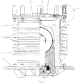
- FIG. 1 is a voltage converter 1 for use Railcar shown with electric drive.
- the Voltage converter 1 is on a mounting flange 2 attached, for mounting on a not shown Railcar serves.
- the mounting flange 2 carries the voltage converter 1 additionally a voltage converter 1 as a cylinder jacket surrounding and open to the top, tubular glass fiber reinforced plastic existing section of the Sheath 3.
- an overpressure protection device 6 intended on the open top of the cylindrical Section of the casing 3 . This consists of one, the cylinder jacket upward closing cover 7, on the top and so that outside compression springs 8 are arranged radially.
- Cover 7 and mounting flange 2 are two metal Flanges - cover flange 13 and lower Mounting flange- with the tubular section of the Cover 3 connected, the two flanges in the tubular portion of the shell 3 are cemented.
- Mounting flange 2, tubular section and Overpressure protection 6 form a voltage converter 1 completely enclosing shell 3.
- the outer surface of the tubular portion of the sheath 3 has circumferential silicone screens 4 shaped like ribs on that by means of vulcanization with the tubular Section are connected.
- the umbrellas ensure that safe operation of the voltage converter necessary Creepage distances and distances.
- Foam mass for example as a foam layer 5 be brought in by the force of an explosion is further reduced. It is between shell 3 and Voltage converter 1 left an expansion space 18.
- the pressure relief device 6 consists of one tubular section of the shell 3 closing upwards Cover 7, on the top and thus outside compression springs 8 are arranged radially.
- the compression springs 8 press the Cover 7 to the cover flange 13.
- such a compression spring 8 is in one Detailed view shown.
- the protective hood 16 is on a base 23 attached to the top of the cover 7 mounted with a central hole.
- a bolt 9 Through the through the spiral curvature of the spring formed spring interior is a bolt 9 with a head 10 so that the upper end the compression spring 8 bears against the head 10 of the bolt 9.
- the bolt 9 is also through the base 23, a Opening 11 in the cover 7 and an opening 12 in the cover flange 13 of the shell 3 out.
- the bolt 9 On the head 10 opposite lying end, the bolt 9 has a thread 14.
- On the thread 14 is a nut 15 screwed on.
- the compression spring 8 With help of the bolt 9 with head 10, the compression spring 8 against the Cover 7 and the flange 13 of the shell 3 biased.
- the Abutments of the compression spring 8 are thereby through the head 10 and the nut 15 are formed, the compression spring 8 is supported against the head 10 and the base 23.
- the Compression spring 8 is in the closed state shown Overpressure protection by 30% of its length, for example biased.
- the edge region 17 of the lid 7 is down as Angled edge contour.
- the angle is in this Embodiment 90 °.
- the one running overleaf Edge contour 17 prevents the possibility of direct attack of weather-related environmental influences on the Overpressure protection 6 and the voltage converter 1.
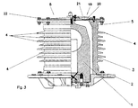
- the pressure relief device 6 is as Burst device 19 formed with an opening 20, the is closed with bursting film 21.
- the bursting device 19 is with the sleeve 3 by means of the circumference of the bursting device 19 screws 22 screwed.
- the Bursting device 19 is dimensioned such that when it is reached the bursting film 21 tears open at a certain internal pressure and the internal pressure escapes in the opening direction.
Landscapes
- Engineering & Computer Science (AREA)
- Power Engineering (AREA)
- Housings And Mounting Of Transformers (AREA)
- Casings For Electric Apparatus (AREA)
- Emergency Protection Circuit Devices (AREA)
- Measuring Fluid Pressure (AREA)
- Coils Or Transformers For Communication (AREA)
- Gas-Insulated Switchgears (AREA)
- Dc-Dc Converters (AREA)
Abstract
Description
- Fig. 1:
- eine Darstellung des Spannungswandlers mit Hülle und Überdrucksicherung mittels Deckel,
- Fig.2:
- eine Detailansicht der Druckfeder mit Bolzen und
- Fig.3:
- eine Darstellung des Spannungswandlers mit Hülle und Überdrucksicherung mittels Berstscheibe.
- 1
- Spannungswandler
- 2
- Montageflansch
- 3
- Hülle
- 4
- Schirme
- 5
- Schaummasse
- 6
- Überdrucksicherung
- 7
- Deckel
- 8
- Druckfedern
- 9
- Bolzen
- 10
- Kopf
- 11
- Öffnung im Deckel
- 12
- Öffnung im Deckelflansch
- 13
- Deckelflansch
- 14
- Gewinde
- 15
- Mutter
- 16
- Schutzhaube
- 17
- Randkontur
- 18
- Expansionsraum
- 19
- Bersteinrichtung
- 20
- Überdrucksicherungsöffnung im Deckel
- 21
- Berstfolie
- 22
- Befestigungsschrauben
- 23
- Sockel
Claims (10)
- Spannungswandler, insbesondere Spannungswandler auf Triebwagen mit elektrischem Antrieb,
dadurch gekennzeichnet, daß der Spannungswandler eine umschließende Hülle (3) als Schutzvorrichtung, vorzugsweise mit Überdrucksicherung (6) aufweist. - Spannungswandler nach Anspruch 1,
dadurch gekennzeichnet, daß die Hülle (3) einen Abschnitt aufweist, der rohrförmig, insbesondere zylinderförmig ausgebildet ist. - Spannungswandler nach Anspruch 1 oder 2,
dadurch gekennzeichnet, daß der rohrförmige Abschnitt der Hülle (3) aus glasfaserverstärktem Kunststoff, vorzugsweise in gewickelter Ausführung besteht. - Spannungswandler nach Anspruch 1, 2 oder 3,
dadurch gekennzeichnet, daß der rohrförmige Abschnitt der Hülle (3) außen rippenartig geformte umlaufende Schirme (4), vorzugsweise aus Silikon aufweist. - Spannungswandler nach einem oder mehreren der obenstehenden Ansprüche,
dadurch gekennzeichnet, daß zwischen Spannungswandler (1) und Hülle (3) eine Schaummasse (5) eingebracht ist, die vorzugsweise flammhemmend ausgerüstet ist. - Spannungswandler nach einem oder mehreren der oben stehenden Ansprüche,
dadurch gekennzeichnet, daß der rohrförmige Abschnitt der Hülle (3) oben von einem Deckel (7) verschlossen ist, der eine Überdrucksicherung (6) aufweist, wobei vorzugsweise zwischen Überdrucksicherung (6) und Spannungswandler (1) und Schaummasse (5) ein Expansionsraum (18) vorgesehen ist. - Spannungswandler nach einem oder mehreren der oben stehenden Ansprüche,
dadurch gekennzeichnet, daß die Überdrucksicherung (6) den rohrförmigen Abschnitt unter Federdruck abschließend als Deckel (7) ausgebildet ist, wobei vorzugsweise der rohrförmige Abschnitt an seinem oberen Ende einen Deckelflansch (13) für den Deckel (7) aufweist. - Spannungswandler nach einem oder mehreren der oben stehenden Ansprüche,
dadurch gekennzeichnet, daß zwischen Deckel (7) und Deckelflansch (13) Bolzen (9) mit Kopf (10) und zumindest einem Gewinde (14) an dem dem Kopf (10) gegenüberliegendem Ende des Bolzen (9) vorgesehen sind, wobei jeder Bolzen (9) koaxial durch das Zentrum einer Druckfeder (8), einer Öffnung (11) im Deckel (7) und einer Öffnung (12) im Deckelflansch (13) geführt ist und die Bolzen (9) die Druckfedern (8) gegen den Deckel (7) und den Deckelflansch (13) mittels Muttern (15) vorspannen, wobei vorzugsweise die Druckfedern (8) über den Umfang des Deckels (7) verteilt sind und insbesondere die Druckfedern (8) im geschlossenen Zustand der Überdrucksicherung (6) um etwa 30% ihrer Länge vorgespannt sind. - Spannungswandler nach einem oder mehreren der oben stehenden Ansprüche,
dadurch gekennzeichnet, daß die Druckfedern (8) von einer Schutzhülle (16) umschlossen sind und/oder der Deckel (7) eine nach unten abgewinkelte Randkontur (17) aufweist. - Spannungswandler nach einem oder mehreren der Ansprüche 1 bis 6,
dadurch gekennzeichnet, daß die Überdrucksicherung (6) als Bersteinrichtung (19) mit einer Öffnung (20) im Deckel (7) ausgebildet ist, die vorzugsweise mit Berstfolie (21) verschlossen ist.
Applications Claiming Priority (4)
| Application Number | Priority Date | Filing Date | Title |
|---|---|---|---|
| DE20016065U | 2000-09-16 | ||
| DE20016065U DE20016065U1 (de) | 2000-09-16 | 2000-09-16 | Explosionsgeschützter Bahnwandler |
| DE20107017U | 2001-04-24 | ||
| DE20107017U DE20107017U1 (de) | 2000-09-16 | 2001-04-24 | Spannungswandler |
Publications (3)
| Publication Number | Publication Date |
|---|---|
| EP1189249A2 true EP1189249A2 (de) | 2002-03-20 |
| EP1189249A3 EP1189249A3 (de) | 2002-11-27 |
| EP1189249B1 EP1189249B1 (de) | 2005-11-16 |
Family
ID=26056526
Family Applications (1)
| Application Number | Title | Priority Date | Filing Date |
|---|---|---|---|
| EP01121495A Expired - Lifetime EP1189249B1 (de) | 2000-09-16 | 2001-09-08 | Explosionsgeschützter Spannungswandler |
Country Status (4)
| Country | Link |
|---|---|
| EP (1) | EP1189249B1 (de) |
| AT (1) | ATE310312T1 (de) |
| DE (1) | DE50108068D1 (de) |
| ES (1) | ES2253312T3 (de) |
Cited By (2)
| Publication number | Priority date | Publication date | Assignee | Title |
|---|---|---|---|---|
| EP1648001A1 (de) * | 2004-10-15 | 2006-04-19 | KG Ritz Messwandler GmbH & Co. | Spannungswandler für Eisenbahntriebwagen |
| DE202014100486U1 (de) * | 2014-02-04 | 2015-05-05 | Sma Solar Technology Ag | Deformierbares befestigungselement und wechselrichter |
Families Citing this family (2)
| Publication number | Priority date | Publication date | Assignee | Title |
|---|---|---|---|---|
| CN101350247B (zh) * | 2007-07-18 | 2010-09-08 | 大连北方互感器有限公司 | 电力机车用户外干式电压互感器 |
| DE102017203799A1 (de) | 2017-03-08 | 2018-09-13 | RITZ Instrument Transformers GmbH | Berstsicherer Stromwandler, insbesondere für Triebwagen |
Family Cites Families (6)
| Publication number | Priority date | Publication date | Assignee | Title |
|---|---|---|---|---|
| US2904616A (en) * | 1958-03-18 | 1959-09-15 | Mc Graw Edison Co | Encased electrical apparatus having pressure relief means |
| DE2624882A1 (de) * | 1976-06-03 | 1977-12-15 | Transformatoren Union Ag | Ueberdruckschutzeinrichtung fuer mit isolierfluessigkeit oder isoliergas gefuellte elektrische maschinen und apparate |
| DE2749659A1 (de) * | 1977-11-05 | 1979-05-10 | Balteau Sa | Messwandler |
| JPS622505A (ja) * | 1985-06-27 | 1987-01-08 | Toshiba Corp | 変圧器 |
| FR2713837B1 (fr) * | 1993-12-08 | 1996-01-12 | Merlin Gerin | Dispositif de protection pour transformateur. |
| JP3532758B2 (ja) * | 1998-02-27 | 2004-05-31 | 三菱電機株式会社 | 計器用変成器 |
-
2001
- 2001-09-08 ES ES01121495T patent/ES2253312T3/es not_active Expired - Lifetime
- 2001-09-08 AT AT01121495T patent/ATE310312T1/de active
- 2001-09-08 DE DE50108068T patent/DE50108068D1/de not_active Expired - Lifetime
- 2001-09-08 EP EP01121495A patent/EP1189249B1/de not_active Expired - Lifetime
Cited By (2)
| Publication number | Priority date | Publication date | Assignee | Title |
|---|---|---|---|---|
| EP1648001A1 (de) * | 2004-10-15 | 2006-04-19 | KG Ritz Messwandler GmbH & Co. | Spannungswandler für Eisenbahntriebwagen |
| DE202014100486U1 (de) * | 2014-02-04 | 2015-05-05 | Sma Solar Technology Ag | Deformierbares befestigungselement und wechselrichter |
Also Published As
| Publication number | Publication date |
|---|---|
| EP1189249B1 (de) | 2005-11-16 |
| ATE310312T1 (de) | 2005-12-15 |
| EP1189249A3 (de) | 2002-11-27 |
| DE50108068D1 (de) | 2005-12-22 |
| ES2253312T3 (es) | 2006-06-01 |
Similar Documents
| Publication | Publication Date | Title |
|---|---|---|
| EP0132634B1 (de) | Elektrischer Kondensator mit Überdruckabreisssicherung | |
| EP2842138B1 (de) | Vorrichtung zum ableiten einer elektrischen überspannung | |
| DE102017207629B4 (de) | Anordnung mit einer Gasdruckfeder für eine Seil-Rotationspendel-Kinematik und Verwendung der Anordnung zum Schalten | |
| EP1189249B1 (de) | Explosionsgeschützter Spannungswandler | |
| DE3511084A1 (de) | Ueberspannungsableiter | |
| EP1604138A1 (de) | Druckentlastungsventil | |
| EP2250687B1 (de) | Entgasungssystem für einen akkumulator und akkumulator mit einem entgasungssystem | |
| DE2800208A1 (de) | Keramischer huellisolator mit druckgasfuellung, insbesondere fuer elektrische anlagen und geraete | |
| DE20107017U1 (de) | Spannungswandler | |
| DE102008013186A1 (de) | Entgasungssystem für einen Akkumulator, Akkumulatorgehäuse und Akkumulator mit einem Entgasungssystem | |
| DE69212536T2 (de) | Vorrichtung zum Schutz gegen Auswirkungen eines Überschlags für Kabelendverschluss | |
| DE102013107559A1 (de) | Bersteinrichtung für ein Hochspannungsgerät | |
| EP3373313A1 (de) | Berstsicherer stromwandler, insbesondere für triebwagen | |
| EP1648001B1 (de) | Spannungswandler für Eisenbahntriebwagen | |
| DE10112413C2 (de) | Notausstiegsluke für einen flugfähigen Flugzeugprototyp | |
| DE69005760T2 (de) | Überspannungsableiter mit visueller Fehleranzeigevorrichtung. | |
| EP0492753A1 (de) | Vorrichtung zur Druckgasentlastung an einer metallgekapselten, druckgasisolierten Schaltanlage | |
| EP3934036B1 (de) | Hochspannungsdurchführung und elektrische hochspannungseinrichtung mit hochspannungsdurchführung | |
| DE102019111899A1 (de) | Verschalung eines Turboladers und Turbolader | |
| DE102018203383A1 (de) | Abtrennanordnung für einen Überspannungsableiter, Überspannungsableiter und Verfahren zur Installation eines Überspannungsableiters | |
| DE2508605B2 (de) | Abdeckvorrichtung für eine Explosionsdruck-Ableitöffnung eines Innenraums | |
| EP3400637B1 (de) | Demontage- oder montageverfahren für eine druckfluidisolierte elektroenergieübertragungseinrichtung | |
| DE69822690T2 (de) | Gasisolierter Transformator | |
| DE2739030A1 (de) | Metallgekapselte, gasisolierte hochspannungsanlage mit einer druckentlastungseinrichtung | |
| EP3133613A1 (de) | Koronaring |
Legal Events
| Date | Code | Title | Description |
|---|---|---|---|
| PUAI | Public reference made under article 153(3) epc to a published international application that has entered the european phase |
Free format text: ORIGINAL CODE: 0009012 |
|
| AK | Designated contracting states |
Kind code of ref document: A2 Designated state(s): AT BE CH CY DE DK ES FI FR GB GR IE IT LI LU MC NL PT SE TR |
|
| AX | Request for extension of the european patent |
Free format text: AL;LT;LV;MK;RO;SI |
|
| PUAL | Search report despatched |
Free format text: ORIGINAL CODE: 0009013 |
|
| AK | Designated contracting states |
Kind code of ref document: A3 Designated state(s): AT BE CH CY DE DK ES FI FR GB GR IE IT LI LU MC NL PT SE TR |
|
| AX | Request for extension of the european patent |
Free format text: AL;LT;LV;MK;RO;SI |
|
| RIC1 | Information provided on ipc code assigned before grant |
Free format text: 7H 01F 27/40 A, 7H 01F 38/26 B |
|
| 17P | Request for examination filed |
Effective date: 20021122 |
|
| AKX | Designation fees paid |
Designated state(s): AT BE CH CY DE DK ES FI FR GB GR IE IT LI LU MC NL PT SE TR |
|
| RAP1 | Party data changed (applicant data changed or rights of an application transferred) |
Owner name: KGRITZ MESSWANDLER GMBH & CO. |
|
| 17Q | First examination report despatched |
Effective date: 20040825 |
|
| GRAP | Despatch of communication of intention to grant a patent |
Free format text: ORIGINAL CODE: EPIDOSNIGR1 |
|
| GRAS | Grant fee paid |
Free format text: ORIGINAL CODE: EPIDOSNIGR3 |
|
| GRAA | (expected) grant |
Free format text: ORIGINAL CODE: 0009210 |
|
| AK | Designated contracting states |
Kind code of ref document: B1 Designated state(s): AT BE CH CY DE DK ES FI FR GB GR IE IT LI LU MC NL PT SE TR |
|
| PG25 | Lapsed in a contracting state [announced via postgrant information from national office to epo] |
Ref country code: NL Free format text: LAPSE BECAUSE OF FAILURE TO SUBMIT A TRANSLATION OF THE DESCRIPTION OR TO PAY THE FEE WITHIN THE PRESCRIBED TIME-LIMIT Effective date: 20051116 Ref country code: IE Free format text: LAPSE BECAUSE OF FAILURE TO SUBMIT A TRANSLATION OF THE DESCRIPTION OR TO PAY THE FEE WITHIN THE PRESCRIBED TIME-LIMIT Effective date: 20051116 Ref country code: FI Free format text: LAPSE BECAUSE OF FAILURE TO SUBMIT A TRANSLATION OF THE DESCRIPTION OR TO PAY THE FEE WITHIN THE PRESCRIBED TIME-LIMIT Effective date: 20051116 |
|
| REG | Reference to a national code |
Ref country code: GB Ref legal event code: FG4D Free format text: NOT ENGLISH |
|
| REG | Reference to a national code |
Ref country code: CH Ref legal event code: EP |
|
| REG | Reference to a national code |
Ref country code: IE Ref legal event code: FG4D Free format text: LANGUAGE OF EP DOCUMENT: GERMAN |
|
| REF | Corresponds to: |
Ref document number: 50108068 Country of ref document: DE Date of ref document: 20051222 Kind code of ref document: P |
|
| REG | Reference to a national code |
Ref country code: CH Ref legal event code: NV Representative=s name: PATENTANWALTSBUERO URSULA RENFER-VONNEMANN |
|
| GBT | Gb: translation of ep patent filed (gb section 77(6)(a)/1977) |
Effective date: 20060118 |
|
| REG | Reference to a national code |
Ref country code: SE Ref legal event code: TRGR |
|
| PG25 | Lapsed in a contracting state [announced via postgrant information from national office to epo] |
Ref country code: GR Free format text: LAPSE BECAUSE OF FAILURE TO SUBMIT A TRANSLATION OF THE DESCRIPTION OR TO PAY THE FEE WITHIN THE PRESCRIBED TIME-LIMIT Effective date: 20060216 Ref country code: DK Free format text: LAPSE BECAUSE OF FAILURE TO SUBMIT A TRANSLATION OF THE DESCRIPTION OR TO PAY THE FEE WITHIN THE PRESCRIBED TIME-LIMIT Effective date: 20060216 |
|
| PG25 | Lapsed in a contracting state [announced via postgrant information from national office to epo] |
Ref country code: PT Free format text: LAPSE BECAUSE OF FAILURE TO SUBMIT A TRANSLATION OF THE DESCRIPTION OR TO PAY THE FEE WITHIN THE PRESCRIBED TIME-LIMIT Effective date: 20060417 |
|
| NLV1 | Nl: lapsed or annulled due to failure to fulfill the requirements of art. 29p and 29m of the patents act | ||
| REG | Reference to a national code |
Ref country code: ES Ref legal event code: FG2A Ref document number: 2253312 Country of ref document: ES Kind code of ref document: T3 |
|
| REG | Reference to a national code |
Ref country code: IE Ref legal event code: FD4D |
|
| ET | Fr: translation filed | ||
| PLBE | No opposition filed within time limit |
Free format text: ORIGINAL CODE: 0009261 |
|
| STAA | Information on the status of an ep patent application or granted ep patent |
Free format text: STATUS: NO OPPOSITION FILED WITHIN TIME LIMIT |
|
| PG25 | Lapsed in a contracting state [announced via postgrant information from national office to epo] |
Ref country code: MC Free format text: LAPSE BECAUSE OF NON-PAYMENT OF DUE FEES Effective date: 20060930 Ref country code: BE Free format text: LAPSE BECAUSE OF NON-PAYMENT OF DUE FEES Effective date: 20060930 |
|
| 26N | No opposition filed |
Effective date: 20060817 |
|
| BERE | Be: lapsed |
Owner name: KG RITZ MESSWANDLER G.M.B.H. & CO. Effective date: 20060930 |
|
| PG25 | Lapsed in a contracting state [announced via postgrant information from national office to epo] |
Ref country code: LU Free format text: LAPSE BECAUSE OF NON-PAYMENT OF DUE FEES Effective date: 20060908 |
|
| PG25 | Lapsed in a contracting state [announced via postgrant information from national office to epo] |
Ref country code: CY Free format text: LAPSE BECAUSE OF FAILURE TO SUBMIT A TRANSLATION OF THE DESCRIPTION OR TO PAY THE FEE WITHIN THE PRESCRIBED TIME-LIMIT Effective date: 20051116 |
|
| REG | Reference to a national code |
Ref country code: CH Ref legal event code: NV Representative=s name: KATZAROV S.A. |
|
| REG | Reference to a national code |
Ref country code: FR Ref legal event code: PLFP Year of fee payment: 15 |
|
| REG | Reference to a national code |
Ref country code: FR Ref legal event code: PLFP Year of fee payment: 16 |
|
| REG | Reference to a national code |
Ref country code: FR Ref legal event code: PLFP Year of fee payment: 17 |
|
| REG | Reference to a national code |
Ref country code: CH Ref legal event code: PCAR Free format text: NEW ADDRESS: AVENUE DES MORGINES 12, 1213 PETIT-LANCY (CH) |
|
| REG | Reference to a national code |
Ref country code: FR Ref legal event code: PLFP Year of fee payment: 18 |
|
| PGFP | Annual fee paid to national office [announced via postgrant information from national office to epo] |
Ref country code: GB Payment date: 20200929 Year of fee payment: 20 Ref country code: FR Payment date: 20200924 Year of fee payment: 20 Ref country code: TR Payment date: 20200902 Year of fee payment: 20 |
|
| PGFP | Annual fee paid to national office [announced via postgrant information from national office to epo] |
Ref country code: AT Payment date: 20200923 Year of fee payment: 20 Ref country code: SE Payment date: 20200929 Year of fee payment: 20 Ref country code: CH Payment date: 20200930 Year of fee payment: 20 |
|
| PGFP | Annual fee paid to national office [announced via postgrant information from national office to epo] |
Ref country code: ES Payment date: 20201016 Year of fee payment: 20 Ref country code: IT Payment date: 20200925 Year of fee payment: 20 Ref country code: DE Payment date: 20201125 Year of fee payment: 20 |
|
| REG | Reference to a national code |
Ref country code: DE Ref legal event code: R071 Ref document number: 50108068 Country of ref document: DE |
|
| REG | Reference to a national code |
Ref country code: CH Ref legal event code: PL |
|
| REG | Reference to a national code |
Ref country code: GB Ref legal event code: PE20 Expiry date: 20210907 |
|
| REG | Reference to a national code |
Ref country code: AT Ref legal event code: MK07 Ref document number: 310312 Country of ref document: AT Kind code of ref document: T Effective date: 20210908 |
|
| PG25 | Lapsed in a contracting state [announced via postgrant information from national office to epo] |
Ref country code: GB Free format text: LAPSE BECAUSE OF EXPIRATION OF PROTECTION Effective date: 20210907 |
|
| REG | Reference to a national code |
Ref country code: ES Ref legal event code: FD2A Effective date: 20220126 |
|
| PG25 | Lapsed in a contracting state [announced via postgrant information from national office to epo] |
Ref country code: ES Free format text: LAPSE BECAUSE OF EXPIRATION OF PROTECTION Effective date: 20210909 |