EP1189006A2 - Cooler arrangement - Google Patents
Cooler arrangement Download PDFInfo
- Publication number
- EP1189006A2 EP1189006A2 EP01118936A EP01118936A EP1189006A2 EP 1189006 A2 EP1189006 A2 EP 1189006A2 EP 01118936 A EP01118936 A EP 01118936A EP 01118936 A EP01118936 A EP 01118936A EP 1189006 A2 EP1189006 A2 EP 1189006A2
- Authority
- EP
- European Patent Office
- Prior art keywords
- cooler arrangement
- cooler
- coolers
- flat tubes
- edge
- Prior art date
- Legal status (The legal status is an assumption and is not a legal conclusion. Google has not performed a legal analysis and makes no representation as to the accuracy of the status listed.)
- Granted
Links
- 239000012530 fluid Substances 0.000 claims abstract description 3
- 230000002093 peripheral effect Effects 0.000 claims description 10
- 238000007789 sealing Methods 0.000 claims description 4
- 230000000694 effects Effects 0.000 claims description 2
- 238000001816 cooling Methods 0.000 description 3
- 239000002826 coolant Substances 0.000 description 2
- 239000000110 cooling liquid Substances 0.000 description 2
- 238000005516 engineering process Methods 0.000 description 2
- 238000005476 soldering Methods 0.000 description 2
- 238000011161 development Methods 0.000 description 1
- 230000018109 developmental process Effects 0.000 description 1
- 238000004519 manufacturing process Methods 0.000 description 1
Images


Classifications
-
- F—MECHANICAL ENGINEERING; LIGHTING; HEATING; WEAPONS; BLASTING
- F28—HEAT EXCHANGE IN GENERAL
- F28F—DETAILS OF HEAT-EXCHANGE AND HEAT-TRANSFER APPARATUS, OF GENERAL APPLICATION
- F28F9/00—Casings; Header boxes; Auxiliary supports for elements; Auxiliary members within casings
- F28F9/26—Arrangements for connecting different sections of heat-exchange elements, e.g. of radiators
- F28F9/262—Arrangements for connecting different sections of heat-exchange elements, e.g. of radiators for radiators
-
- F—MECHANICAL ENGINEERING; LIGHTING; HEATING; WEAPONS; BLASTING
- F28—HEAT EXCHANGE IN GENERAL
- F28D—HEAT-EXCHANGE APPARATUS, NOT PROVIDED FOR IN ANOTHER SUBCLASS, IN WHICH THE HEAT-EXCHANGE MEDIA DO NOT COME INTO DIRECT CONTACT
- F28D1/00—Heat-exchange apparatus having stationary conduit assemblies for one heat-exchange medium only, the media being in contact with different sides of the conduit wall, in which the other heat-exchange medium is a large body of fluid, e.g. domestic or motor car radiators
- F28D1/02—Heat-exchange apparatus having stationary conduit assemblies for one heat-exchange medium only, the media being in contact with different sides of the conduit wall, in which the other heat-exchange medium is a large body of fluid, e.g. domestic or motor car radiators with heat-exchange conduits immersed in the body of fluid
- F28D1/04—Heat-exchange apparatus having stationary conduit assemblies for one heat-exchange medium only, the media being in contact with different sides of the conduit wall, in which the other heat-exchange medium is a large body of fluid, e.g. domestic or motor car radiators with heat-exchange conduits immersed in the body of fluid with tubular conduits
- F28D1/0408—Multi-circuit heat exchangers, e.g. integrating different heat exchange sections in the same unit or heat exchangers for more than two fluids
- F28D1/0426—Multi-circuit heat exchangers, e.g. integrating different heat exchange sections in the same unit or heat exchangers for more than two fluids with units having particular arrangement relative to the large body of fluid, e.g. with interleaved units or with adjacent heat exchange units in common air flow or with units extending at an angle to each other or with units arranged around a central element
-
- F—MECHANICAL ENGINEERING; LIGHTING; HEATING; WEAPONS; BLASTING
- F28—HEAT EXCHANGE IN GENERAL
- F28F—DETAILS OF HEAT-EXCHANGE AND HEAT-TRANSFER APPARATUS, OF GENERAL APPLICATION
- F28F9/00—Casings; Header boxes; Auxiliary supports for elements; Auxiliary members within casings
- F28F9/02—Header boxes; End plates
Definitions
- the invention relates to a cooler arrangement consisting of several coolers each have two collecting boxes, two collecting boxes of adjacent coolers form an edge of the cooler assembly, the coolers in at least one Row arranged, connecting the header boxes have flat tubes that arranged transversely to the fan axis of the inside of the cooler arrangement Radial fans run, with a front wall and a rear wall as well as with Zu - And drain lines for at least two coolers through the flat tubes flowing fluid, which are connected to collecting tanks, such that in direct or indirect neighborhood to the end of the first and / or last Flat tube of the at least one row of flat tubes a connecting piece is arranged, the mouth of the collection box in a row with the Mouths of the flat tubes in the collecting box is provided and the Connection of the cooler inlet or outlet pipe permitted.
- the present application is intended to add further design variants to the prior art, which likewise ensure a compact and space-saving cooler arrangement and allow additional connection variants.
- the solution according to the invention results in the cooler arrangement specified in the preamble from the characterizing part of claim 1. Further developments and variants result from claims 2 to 6. Because, according to the characterizing part of claim 1, between two adjacent header boxes forming an edge of the cooler arrangement, in the adjacent longitudinal walls of which at least one flow opening is arranged in order to fluidically connect the assigned coolers, there are further variants for different application and connection possibilities.
- the direct connection of the header boxes between their longitudinal walls also leads to a very compact shape of the cooler arrangement, because no protruding connectors or the like are necessary.
- the fluidic connection between the header boxes also makes a significant contribution to the stability of the cooler arrangement, because the header boxes or the associated coolers have been fixed in their position by this connection.
- the fluidic connection can be located in all edges of the cooler arrangement. However, at least one edge of the arrangement is designed according to the invention. The question of the edges in which the fluidic connection is arranged depends on the circuit connection between the coolers that is desired in each case.
- the adjacent longitudinal walls of the collecting boxes forming an edge of the cooler arrangement can either touch or they can be at a short distance from one another, the distance being sealed by means of suitable sealing means in order to prevent unused cooling air from flowing out.
- the provision of a distance is cheaper in terms of production technology. It is particularly advantageous in the case of spaced-apart longitudinal walls if the flow openings in the adjacent longitudinal walls have an insert which is adapted to the shape of the flow opening and is preferably soldered into the flow opening and if the inserts in the flow openings of adjacent longitudinal walls are sealed off from the outside.
- the inserts consist of a circumferential wall, which has a flange at the top and bottom.
- One flange faces outwards and the other inwards so that the inserts look like a pot with an opening in the bottom of the pot.
- One flange serves as a soldering edge with the flow opening in the longitudinal wall.
- the other flange is used to hold the peripheral part with the seals.
- the seal already mentioned consists of one of the shape of the inserts adapted peripheral part with two circumferential grooves, each with a seal is arranged, the peripheral part with the seals against the wall of the Inserts in the corresponding flow openings have a sealing effect achieved.
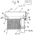
- the connecting piece 12 is arranged in indirect proximity to the end of the first and / or last flat tube 8.1 of the at least one row of flat tubes, the mouth 21 of which in the collecting box 5 is in a row with the mouths 22 of the Flat tubes 8; 8.1 is provided in the collecting box 5 and the connection of the inflow or outflow line 3z; 3a the cooler 2, 6, or 7 allowed.
- the side part 16 and the adjacent corrugated fin 9 are omitted , so that the connecting piece 12 is arranged directly next to the flat tube 8.1 .
- the tube sheet 11 there are openings through which the ends of the flat tubes 8; 8.1 step through.
- Another opening 15 is provided in the projection 17 of the tube sheet 11 to receive the end of the connecting piece 12 .
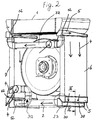
- Fig. 1 shows a variant in which the cooler 2; 6 and 7 of a box-shaped cooler arrangement are connected in series.
- the coolant comes via the inflow line 3z to the connecting piece 12 and enters the collecting tank 5 of the cooler 6 shown on the right. From there it is distributed to the flat tubes 8.1; 8 and flows to the lower header 5 of the same cooler 6.
- This header 5 forms with the header 5 of the lower radiator 2 in the picture an edge 23 of the cooler arrangement, the longitudinal walls 24 of the header 5 in this embodiment having a small distance a , like that Fig. 3 shows.
- the collecting tanks 5 are connected in terms of flow technology at the two lower edges 23 of the cooler arrangement, specifically in the same way as (for example) shown in FIG. 3, which will be described later.
- the center pieces of the peripheral part 30 shown in FIG. 3 can only be seen in the lower right edge 23 in FIG. 1. It can be seen, however, that two fluidic connections 25 are provided between the longitudinal walls of the collecting boxes 5 in this exemplary embodiment. Any number could be provided.
- the same fluidic connection is located in the lower left edge 23. It cannot be seen in FIG. 1.
- the coolant can flow according to the flow arrows 4 shown in the header 5 of the lower cooler 2 , via the flat tubes 8; 8.1 go to the other collecting tank 5 and from there come further into the left cooler 7 in order to leave the cooler arrangement via the drain line 3a, top left.
- 1 shows that a radial fan 10 is arranged in the box-shaped cooler arrangement.
- the flat tubes 8, 8.1 of the coolers 1, 2, 6 and 7 run transversely to the fan axis V.
- the rear of the cooler arrangement is closed by a rear wall R.
- the front has a front wall F with an air inlet opening (not shown) and a nozzle.
- the coolers 2 and 6 are connected in series and the cooler 7 in parallel. Only the reference numerals that were used in the following description were given there. It is clear that the coolers 1, 2, 6 and 7 there also have flat tubes 8; 8.1 and all other necessary features that have been described in FIG. 1.
- In the upper area of the cooler arrangement there is an inflow line 3z which can be plugged together from standard parts, and at the bottom, on the left, there is also an outflow line 3a of the type described in principle in the parent application. However, the arrangement has been changed so that the circuit variant already mentioned is obtained.
- the inlet is located on the top left in FIG. 2.
- FIG. 1 Via the supply line 3z, the cooler 6 and 7 are connected to each other, so that the feed stream splits in the cooler 6 and 7.
- FIG. 2 It enters through the connecting piece 12 in both coolers 6, 7 and their collecting boxes 5 .
- the flow arrows 4 also show how the arrangement is flowed through.
- the right edge 23, which is formed by a collecting tank 5 of the coolers 6 and 2 there are the fluidic connections already described in connection with FIG. 1, of which only a part 30 is also recognizable.
- the cooling liquid can therefore flow into the cooler 2 in order to be further cooled there by the cooling air flow generated by the radial fan 10 .
- the design of the inserts 27 and the seals 32 could be modified accordingly for both variants.
- a flange could also be located on the corresponding flow opening 25 .
- the variant shown in FIG. 3 has an insert 27 in the corresponding flow openings 25 in the longitudinal walls 24 of both collecting tanks 5 , which consists of a circumferential wall part 28 and an inward and an outward flange 29 .
- the insert 27 is supported in the respective flow opening 25 with one outwardly directed flange 29 and thus provides a suitable soldering surface with the flow opening 25.
- the other inwardly directed flange 29 projects into the collecting box 5 by a small amount.
- This flange 29 serves to receive a peripheral part 30 provided for sealing.
- the peripheral part 30 is equipped with grooves 31 , in which seals 32 are inserted. In the shown, ready-to-use or assembled state, the seals 32 press against the respective wall part 28 of the corresponding insert 30 from the inside , as a result of which the cooling liquid must be prevented from escaping. From FIG. 3 and this description it can also be seen that the fluidic connection contributes significantly to the stability of the cooler arrangement, because the individual coolers have been fixed in their position by this connection.
- the shape of the flow openings 25, the inserts 27 and the peripheral part 30 can be any. In the simplest case, the circular shape is selected.
Landscapes
- Engineering & Computer Science (AREA)
- Physics & Mathematics (AREA)
- Thermal Sciences (AREA)
- Mechanical Engineering (AREA)
- General Engineering & Computer Science (AREA)
- Heat-Exchange Devices With Radiators And Conduit Assemblies (AREA)
- Cooling Or The Like Of Semiconductors Or Solid State Devices (AREA)
- Semiconductor Lasers (AREA)
- Air-Conditioning For Vehicles (AREA)
- Cooling Or The Like Of Electrical Apparatus (AREA)
Abstract
Die Erfindung betrifft eine Kühleranordnung bestehend aus mehreren Kühlern (2, 6, 7), die je zwei Sammelkästen (5) aufweisen, wobei zwei Sammelkästen (5) benachbarter Kühler mit ihrer Längswand (24) eine Kante (23) der Kühleranordnung bilden, wobei die Kühler (2; 6; 7) in mindestens einer Reihe angeordnete, die Sammelkästen (5) verbindende Flachrohre (8) aufweisen, die quer zur Ventilatorachse (V) des im Inneren der Kühleranordnung angeordneten Radialventilators (10) verlaufen, mit einer Frontwand (F) und einer Rückwand (R) sowie mit Zu - und Abflußleitungen (3z; 3a) für durch die Flachrohre (8) wenigstens zweier Kühler strömendes Fluid, die an Sammelkästen (5) angeschlossen sind, derart, daß in direkter oder indirekter Nachbarschaft zu dem Ende des ersten und / oder letzten Flachrohrs (8.1) der mindestens einen Flachrohr - Reihe ein Anschlußstutzen (12) angeordnet ist, dessen Mündung (21) in den Sammelkasten (5) in einer Reihe mit den Mündungen (22) der Flachrohre (8; 8.1) in den Sammelkasten (5) vorgesehen ist und der den Anschluß der Zu - oder Abflußleitung (3z; 3a) der Kühler (2, 6, 7) gestattet. Es werden dem Stand der Technik weitere gestalterische Varianten einer kompakten und raumsparenden Kühleranordnung hinzugefügt, wenn erfindungsgemäß zwischen zwei benachbarten, eine Kante (23) der Kühleranordnung ausbildenden Sammelkästen (5), in deren benachbarten Längswänden (24) mindestens jeweils eine Strömungsöffnung (25) angeordnet ist, um die zugeordneten Kühler (6; 2) in wenigstens einer Kante (23) der Kühleranordnung strömungstechnisch zu verbinden. <IMAGE>The invention relates to a cooler arrangement comprising a plurality of coolers (2, 6, 7), each having two header boxes (5), two header boxes (5) of adjacent coolers with their longitudinal wall (24) forming an edge (23) of the cooler arrangement, whereby the coolers (2; 6; 7) have flat tubes (8) arranged in at least one row and connecting the collecting tanks (5) and running transversely to the fan axis (V) of the radial fan (10) arranged in the interior of the cooler arrangement, with a front wall ( F) and a rear wall (R) as well as with inflow and outflow lines (3z; 3a) for fluid flowing through the flat tubes (8) of at least two coolers, which are connected to header boxes (5), in such a way that in direct or indirect proximity to At the end of the first and / or last flat tube (8.1) of the at least one row of flat tubes, a connecting piece (12) is arranged, its mouth (21) in the collecting box (5) in a row with the mouths (22) of the flat tubes (8; 8.1) is provided in the collecting box (5) and which connects the inflow or outflow line (3z; 3a) the cooler (2, 6, 7) is permitted. Further design variants of a compact and space-saving cooler arrangement are added to the prior art if, according to the invention, at least one flow opening (25) is arranged in each case between two adjacent header boxes (5) forming an edge (23) of the cooler arrangement, in their adjacent longitudinal walls (24) in order to fluidically connect the assigned coolers (6; 2) in at least one edge (23) of the cooler arrangement. <IMAGE>
Description
Die Erfindung betrifft eine Kühleranordnung, bestehend aus mehreren Kühlern, die je zwei Sammelkästen aufweisen, wobei zwei Sammelkästen benachbarter Kühler eine Kante der Kühleranordnung bilden, wobei die Kühler in mindestens einer Reihe angeordnete, die Sammelkästen verbindende Flachrohre aufweisen, die quer zur Ventilatorachse des im Inneren der Kühleranordnung angeordneten Radialventilators verlaufen, mit einer Frontwand und einer Rückwand sowie mit Zu - und Abflußleitungen für durch die Flachrohre wenigstens zweier Kühler strömendes Fluid, die an Sammelkästen angeschlossen sind, derart, daß in direkter oder indirekter Nachbarschaft zu dem Ende des ersten und / oder letzten Flachrohrs der mindestens einen Flachrohr - Reihe ein Anschlußstutzen angeordnet ist, dessen Mündung in den Sammelkasten in einer Reihe mit den Mündungen der Flachrohre in den Sammelkasten vorgesehen ist und der den Anschluß der Zu - oder Abflußleitung der Kühler gestattet.The invention relates to a cooler arrangement consisting of several coolers each have two collecting boxes, two collecting boxes of adjacent coolers form an edge of the cooler assembly, the coolers in at least one Row arranged, connecting the header boxes have flat tubes that arranged transversely to the fan axis of the inside of the cooler arrangement Radial fans run, with a front wall and a rear wall as well as with Zu - And drain lines for at least two coolers through the flat tubes flowing fluid, which are connected to collecting tanks, such that in direct or indirect neighborhood to the end of the first and / or last Flat tube of the at least one row of flat tubes a connecting piece is arranged, the mouth of the collection box in a row with the Mouths of the flat tubes in the collecting box is provided and the Connection of the cooler inlet or outlet pipe permitted.
Mit der vorstehend beschriebenen, bisher unveröffentlichten Anmeldung DE 100 41 794.9 wurde eine kompakte und raumsparende Gestaltung der Kühleranordnung erzielt sowie verschiedene Einsatz - und Anschlußmöglichkeiten der Kühleranordnung zur Verfügung gestellt.With the previously unpublished application described above DE 100 41 794.9 was a compact and space-saving design of the Achieved cooler arrangement as well as various application and connection options provided the cooler assembly.
Mit der vorliegenden Anmeldung sollen dem Stand der Technik weitere
gestalterische Varianten hinzugefügt werden, die ebenfalls eine kompakte und
raumsparende Kühleranordnung gewährleisten und zusätzliche Anschlußvarianten
zulassen.
Die erfindungsgemäße Lösung ergibt sich bei der im Oberbegriff angegebenen
Kühleranordnung aus dem kennzeichnenden Teil des Anspruchs 1.
Weiterbildungen und Varianten ergeben sich aus den Ansprüchen 2 bis 6.
Weil, gemäß dem Kennzeichen des Anspruchs 1, zwischen zwei benachbarten,
eine Kante der Kühleranordnung ausbildenden Sammelkästen, in deren
benachbarten Längswänden mindestens eine Strömungsöffnung angeordnet ist,
um die zugeordneten Kühler strömungstechnisch zu verbinden, ergeben sich
weitere Varianten für verschiedene Einsatz - und Anschlußmöglichkeiten. Die
direkte Verbindung der Sammelkästen zwischen ihren Längswänden führt ferner
zu einer sehr kompakten Gestalt der Kühleranordnung, weil keine vorstehenden
Anschlußstücke oder dergleichen notwendig sind. Gegenüber der
Stammanmeldung können mit weniger Aufwand für die Zu - und Abflußleitungen
unterschiedliche Schaltungsvarianten mehrerer Kühler - in Reihe oder parallel -
realisiert werden. Die strömungstechnische Verbindung zwischen den
Sammelkästen leistet darüber hinaus einen wesentlichen Beitrag zur Stabilität der
Kühleranordnung, denn die Sammelkästen bzw. die zugehörigen Kühler sind durch
diese Verbindung in ihrer Position fixiert worden. Die strömungstechnische
Verbindung kann sich in allen Kanten der Kühleranordnung befinden. Mindestens
eine Kante der Anordnung ist jedoch erfindungsgemäß ausgebildet. Die Frage, in
welchen Kanten die strömungstechnische Verbindung angeordnet ist, hängt von
der jeweils gewünschten Schaltungsverbindung zwischen den Kühlern ab.
Die benachbarten Längswände der eine Kante der Kühleranordnung ausbildenden
Sammelkästen können sich entweder berühren oder sie können einen geringen
Abstand zueinander besitzen, wobei der Abstand mittels geeigneter Dichtmittel
abgedichtet ist, um das Abströmen ungenutzter Kühlluft zu verhindern. Das
Vorsehen eines Abstandes ist fertigungstechnisch günstiger.
Es ist insbesondere bei beabstandeten Längswänden von Vorteil, wenn die
Strömungsöffnungen in den benachbarten Längswänden einen an die Form der
Strömungsöffnung angepaßten Einsatz aufweisen, der vorzugsweise in der
Strömungsöffnung eingelötet ist und wenn die Einsätze in den
Strömungsöffnungen benachbarter Längswände nach außen abgedichtet sind.
Die Einsätze bestehen aus einer umlaufenden Wand, die am oberen und unteren
Abschluß je einen Flansch aufweist. Der eine Flansch ist nach außen gerichtet und
der andere nach innen, so daß die Einsätze topfähnlich, mit einer Öffnung im
Boden des Topfes, aussehen. Der eine Flansch dient als Lötrand mit der
Strömungsöffnung in der Längswand. Der andere Flansch dient der Aufnahme des
Umfangsteils mit den Dichtungen.The present application is intended to add further design variants to the prior art, which likewise ensure a compact and space-saving cooler arrangement and allow additional connection variants.
The solution according to the invention results in the cooler arrangement specified in the preamble from the characterizing part of
Because, according to the characterizing part of
The adjacent longitudinal walls of the collecting boxes forming an edge of the cooler arrangement can either touch or they can be at a short distance from one another, the distance being sealed by means of suitable sealing means in order to prevent unused cooling air from flowing out. The provision of a distance is cheaper in terms of production technology.
It is particularly advantageous in the case of spaced-apart longitudinal walls if the flow openings in the adjacent longitudinal walls have an insert which is adapted to the shape of the flow opening and is preferably soldered into the flow opening and if the inserts in the flow openings of adjacent longitudinal walls are sealed off from the outside.
The inserts consist of a circumferential wall, which has a flange at the top and bottom. One flange faces outwards and the other inwards so that the inserts look like a pot with an opening in the bottom of the pot. One flange serves as a soldering edge with the flow opening in the longitudinal wall. The other flange is used to hold the peripheral part with the seals.
Die bereits erwähnte Abdichtung besteht aus einem der Form der Einsätze angepaßten Umfangsteil mit zwei umlaufenden Nuten, in denen je eine Dichtung angeordnet ist, wobei das Umfangsteil mit den Dichtungen gegen die Wand der Einsätze in den korrespondierenden Strömungsöffnungen eine Dichtwirkung erzielt. The seal already mentioned consists of one of the shape of the inserts adapted peripheral part with two circumferential grooves, each with a seal is arranged, the peripheral part with the seals against the wall of the Inserts in the corresponding flow openings have a sealing effect achieved.
Die Erfindung wird nachfolgend in Ausführungsbeispielen beschrieben, wobei auf die beiliegenden Zeichnungen Bezug genommen wird. Aus dieser Beschreibung können sich weitere, möglicherweise wesentliche, Merkmale und Vorteile ergeben.
- Fig. 1
- perspektivische Ansicht einer ersten Variante der Kühleranordnung;
- Fig. 2
- perspektivische Ansicht einer zweiten Variante der Kühleranordnung;
- Fig. 3
- Schnitt III - III aus Fig. 1 und 2;
- Fig. 4
- Teilschnitt durch einen Kühler gemäß Stammanmeldung;
- Fig. 1
- perspective view of a first variant of the cooler arrangement;
- Fig. 2
- perspective view of a second variant of the cooler arrangement;
- Fig. 3
- Section III - III of Figures 1 and 2;
- Fig. 4
- Partial section through a cooler according to parent registration;
Aus der Fig.4 geht hervor, daß der Anschlußstutzen 12 in indirekter Nachbarschaft
zu dem Ende des ersten und / oder letzten Flachrohrs 8.1 der mindestens einen
Flachrohr - Reihe angeordnet ist, dessen Mündung 21 in den Sammelkasten 5 in
einer Reihe mit den Mündungen 22 der Flachrohre 8; 8.1 in den Sammelkasten 5
vorgesehen ist und der den Anschluß der Zu - oder Abflußleitung 3z; 3a der
Kühler 2, 6, oder 7 gestattet. Bei der hier nicht gezeigten direkten Nachbarschaft
entfällt das Seitenteil 16 und die angrenzende Wellrippe 9, so daß der
Anschlußstutzen 12 direkt neben dem Flachrohr 8.1 angeordnet ist. Im Rohrboden
11 sind Öffnungen vorhanden, durch welche die Enden der Flachrohre 8; 8.1
hindurchtreten. Eine weitere Öffnung 15 ist im Überstand 17 des Rohrbodens 11
vorgesehen, um das Ende des Anschlußstutzens 12 aufzunehmen. Die Stirnseiten
des Sammelkastens 5 sind durch ein Verschlußblech 14 verschlossen. Ferner hat
der Sammelkasten 5 eine Längswand 24. Dieser Sachverhalt entspricht der
Stammanmeldung.
Die Fig. 1 zeigt eine Variante, in der die Kühler 2; 6 und 7 einer kastenförmigen
Kühleranordnung in Reihe geschaltet sind. Die Kühlflüssigkeit kommt über die
Zuflußleitung 3z zum Anschlußstutzen 12 und tritt in den Sammelkasten 5 des im
Bild rechten Kühlers 6 ein. Von dort verteilt sie sich auf die Flachrohre 8.1; 8 und
strömt zum unteren Sammelkasten 5 desselben Kühlers 6. Dieser Sammelkasten
5 bildet mit dem Sammelkasten 5 des im Bild unteren Kühlers 2 eine Kante 23 der
Kühleranordnung aus, wobei die Längswände 24 der Sammelkästen 5 in diesem
Ausführungsbeispiel einen geringen Abstand a besitzen, wie die Fig. 3 zeigt. Die
Sammelkästen 5 sind an den beiden unteren Kanten 23 der Kühleranordnung
strömungstechnisch verbunden und zwar so, wie ebenfalls (beispielsweise) in der
Fig. 3 gezeigt, die später beschrieben wird. Von dieser strömungstechnischen
Verbindung sind in der Fig. 1 lediglich in der rechten, unteren Kante 23 die
Mittelstücke des in Fig. 3 gezeigten Umfangsteils 30 zu erkennen. Es ist jedoch zu
sehen, daß in diesem Ausführungsbeispiel zwei strömungstechnische
Verbindungen 25 zwischen den Längswänden der Sammelkästen 5 vorgesehen
sind. Es könnte eine beliebige Anzahl vorgesehen werden. Die gleiche
strömungstechnische Verbindung befindet sich in der linken, unteren Kante 23. Sie
ist in Fig. 1 nicht zu sehen. Demzufolge kann die Kühlflüssigkeit gemäß den
eingezeichneten Strömungspfeilen 4 in den Sammelkasten 5 des unteren Kühlers
2 einströmen, über dessen nicht gezeichnete Flachrohre 8; 8.1 zum anderen
Sammelkasten 5 gelangen und von dort weiter in den linken Kühler 7 kommen, um
die Kühleranordnung über die Abflußleitung 3a, links oben, zu verlassen. Ferner
zeigt die Fig. 1, daß in der kastenförmigen Kühleranordnung ein Radialventilator 10
angeordnet ist. Die Flachrohre 8, 8.1 der Kühler 1, 2, 6 und 7 verlaufen quer zur
Ventilatorachse V. Die Rückseite der Kühleranordnung ist durch eine Rückwand R
verschlossen. Die Vorderseite besitzt eine Frontwand F mit einer nicht
gezeichneten Luft - Einströmöffnung und einer Düse.4 shows that the connecting
Fig. 1 shows a variant in which the
In der in Fig. 2 abgebildeten Variante sind die Kühler 2 und 6 in Reihe geschaltet
und der Kühler 7 parallel dazu. Dort wurden nur die Bezugszeichen angegeben,
die bei der nachfolgenden Beschreibung benutzt werden. Es ist klar, daß auch die
dortigen Kühler 1, 2, 6 und 7 über Flachrohre 8; 8.1 sowie über alle anderen
notwendigen Merkmale verfügen, die in der Fig. 1 beschrieben worden sind.
Im oberen Bereich der Kühleranordnung befindet sich eine aus Standardteilen
zusammensteckbare Zuflußleitung 3z und unten, links eine ebensolche
Abflußleitung 3a, derart, wie sie prinzipiell in der Stammanmeldung beschrieben
sind. Die Anordnung wurde jedoch verändert, so daß sich die bereits genannte
Schaltungsvariante ergibt. Der Zulauf befindet sich in der Fig. 2 oben, links. Über
die Zuflußleitung 3z sind die Kühler 6 und 7 miteinander verbunden, so daß sich
der Zulaufstrom auf die Kühler 6 und 7 aufteilt. Er tritt über die Anschlußstutzen 12
in beide Kühler 6, 7 bzw. deren Sammelkästen 5 ein. Auch in dieser Abbildung
zeigen die Strömungspfeile 4 an, wie die Anordnung durchströmt wird. In der
rechten, unteren Kante 23, die durch je einen Sammelkasten 5 der Kühler 6 und 2
gebildet ist, befinden sich die bereits im Zusammenhang mit Fig. 1 beschriebenen
strömungstechnischen Verbindungen, von denen ebenfalls nur je ein Teil 30
erkennbar ist. Die Kühlflüssigkeit kann also in den Kühler 2 hineinströmen, um dort
weiter abgekühlt zu werden, durch den vom Radialventilator 10 erzeugten
Kühlluftstrom. Zwischen den in der linken, unteren Kante 23 angeordneten
Sammelkästen 5 der Kühler 2 und 7 hingegen, ist keine strömungstechnische
Verbindung 25 der beschriebenen Art vorhanden. Dafür wurden die dortigen
Sammelkästen 5 in aus Fig. 4 zu erkennender Art und Weise mit Anschlußstutzen
12 versehen, wobei beide Anschlußstutzen 12 über die Abflußleitung 3a zum
Ablauf aus der Kühleranordnung führen.
Die Fig. 3 zeigt nun Einzelheiten der strömungstechnischen Verbindung zwischen
den Sammelkästen 5 der Kühler bzw. zwischen deren Längswänden 24. Gezeigt
ist lediglich die Variante, bei der die Längswände 24 einen geringen Abstand a
voneinander besitzen, wobei der Abstand a durch eine geeignete Dichtung 26 über
die gesamte Länge der Sammelkästen 5 ausgefüllt ist, um das Entweichen
ungenutzter Kühlluft zu verhindern.
Die andere Variante, die keinen solchen Abstand a aufweist und deshalb auch
keine Dichtung 26 benötigt ist nicht gezeigt. Es versteht sich, daß für beide
Varianten die Ausbildung der Einsätze 27 sowie der Dichtungen 32 entsprechend
modifiziert sein könnte. Beispielsweise könnte es ausreichend sein, nur in einer
Strömungsöffnung 25 eines Sammelkastens 5 einen modifizierten Einsatz 27
vorzusehen, der in die korrespondierende Strömungsöffnung 25 des anderen
Sammelkastens 5 eingreift und dort auch abgedichtet ist. Dabei könnte sich auch
ein Flansch an der korrespondierenden Strömungsöffnung 25 befinden.
Die in Fig. 3 gezeigte Variante besitzt in den korrespondierenden
Strömungsöffnungen 25 in den Längswänden 24 beider Sammelkästen 5 je einen
Einsatz 27, der aus einem umlaufenden Wandteil 28 und aus einem nach innen
und einem nach außen gerichteten Flansch 29 besteht. Mit dem einen nach außen
gerichteten Flansch 29 ist der Einsatz 27 in der jeweiligen Strömungsöffnung 25
abgestützt und ergibt somit eine geeignete Lötfläche mit der Strömungsöffnung 25.
Der andere nach innen gerichtete Flansch 29 ragt in den Sammelkasten 5 um
einen geringen Betrag hinein. Dieser Flansch 29 dient dazu, ein zur Abdichtung
vorgesehenes Umfangsteil 30 aufzunehmen. Das Umfangsteil 30 ist mit Nuten 31
ausgestattet, in die Dichtungen 32 eingelegt sind. Im gezeigten, betriebsbereiten
bzw. montierten Zustand drücken die Dichtungen 32 von innen gegen das jeweilige
Wandteil 28 des entsprechenden Einsatzes 30, wodurch das Austreten der
Kühlflüssigkeit zu verhindern ist. Aus der Fig. 3 und dieser Beschreibung ist auch
zu erkennen, daß die strömungstechnische Verbindung zur Stabilität der
Kühleranordnung wesentlich beiträgt, denn die einzelnen Kühler sind durch diese
Verbindung in ihrer Position fixiert worden. Die Form der Strömungsöffnungen 25,
der Einsätze 27 sowie des Umfangsteils 30 kann beliebig sein. Im einfachsten Fall
wird die kreisrunde Form ausgewählt.In the variant shown in Fig. 2, the
In the upper area of the cooler arrangement there is an inflow line 3z which can be plugged together from standard parts, and at the bottom, on the left, there is also an outflow line 3a of the type described in principle in the parent application. However, the arrangement has been changed so that the circuit variant already mentioned is obtained. The inlet is located on the top left in FIG. 2. Via the supply line 3z, the
3 now shows details of the fluidic connection between the
The other variant, which does not have such a distance a and therefore does not require a
The variant shown in FIG. 3 has an
Claims (6)
dadurch gekennzeichnet, daß
zwischen zwei benachbarten, eine Kante (23) der Kühleranordnung ausbildenden Sammelkästen (5), in deren benachbarten Längswänden (24) mindestens jeweils eine Strömungsöffnung (25) angeordnet ist, um die zugeordneten Kühler (6; 2) in wenigstens einer Kante (23) der Kühleranordnung strömungstechnisch zu verbinden.Cooler arrangement, consisting of several coolers (2, 6, 7), each having two header boxes (5), two header boxes (5) of adjacent coolers with their longitudinal wall (24) forming an edge (23) of the cooler arrangement, the coolers ( 2; 6; 7) have flat tubes (8) arranged in at least one row and connecting the header tanks (5) and running transversely to the fan axis (V) of the radial fan (10) arranged inside the cooler arrangement, with a front wall (F) and a rear wall (R) and with inflow and outflow lines (3z; 3a) for fluid flowing through the flat tubes (8) of at least two coolers, which are connected to header boxes (5), such that in direct or indirect proximity to the end of the The first and / or last flat tube (8.1) of the at least one row of flat tubes has a connecting piece (12) whose mouth (21) in the collecting box (5) is in a row with the mouths (22) of the flat tubes (8; 8.1) in the collection box n (5) is provided and which connects the inflow or outflow line (3z; 3a) the cooler (2, 6, 7) allows
characterized in that
between two adjacent collecting boxes (5) forming an edge (23) of the cooler arrangement, in the adjacent longitudinal walls (24) of which at least one flow opening (25) is arranged in each case, around the assigned cooler (6; 2) in at least one edge (23) to connect the cooler arrangement fluidically.
Applications Claiming Priority (2)
| Application Number | Priority Date | Filing Date | Title |
|---|---|---|---|
| DE10045987 | 2000-09-16 | ||
| DE2000145987 DE10045987A1 (en) | 2000-08-25 | 2000-09-16 | Cooling unit with several coolers has two adjacent collecting boxes forming one edge of unit with at least one flow aperture in adjacent longitudinal walls |
Publications (3)
| Publication Number | Publication Date |
|---|---|
| EP1189006A2 true EP1189006A2 (en) | 2002-03-20 |
| EP1189006A3 EP1189006A3 (en) | 2003-10-15 |
| EP1189006B1 EP1189006B1 (en) | 2006-06-14 |
Family
ID=7656544
Family Applications (1)
| Application Number | Title | Priority Date | Filing Date |
|---|---|---|---|
| EP01118936A Expired - Lifetime EP1189006B1 (en) | 2000-09-16 | 2001-08-04 | Cooler arrangement |
Country Status (4)
| Country | Link |
|---|---|
| US (1) | US6675879B2 (en) |
| EP (1) | EP1189006B1 (en) |
| AT (1) | ATE330197T1 (en) |
| DE (2) | DE10041794A1 (en) |
Cited By (1)
| Publication number | Priority date | Publication date | Assignee | Title |
|---|---|---|---|---|
| EP1890217A3 (en) * | 2006-07-25 | 2010-12-08 | Fujitsu Ltd. | Liquid cooling unit and heat exchanger therefor |
Families Citing this family (7)
| Publication number | Priority date | Publication date | Assignee | Title |
|---|---|---|---|---|
| DE10041794A1 (en) | 2000-09-16 | 2002-03-07 | Modine Mfg Co | Cooling assembly, with a number of chill units, has a connection near the end of the leading and/or final flat tube for the inflow/outflow channels, to give a more compact structure |
| CN1668887A (en) * | 2002-06-18 | 2005-09-14 | 昭和电工株式会社 | Unit-type heat exchanger |
| US8002022B2 (en) | 2005-09-16 | 2011-08-23 | Behr Gmbh & Co. Kg | Heat exchanger, in particular exhaust gas heat exchanger for motor vehicles |
| DE102005055482A1 (en) * | 2005-11-18 | 2007-05-24 | Behr Gmbh & Co. Kg | Heat exchanger for an internal combustion engine |
| US20140116658A1 (en) * | 2012-10-30 | 2014-05-01 | Deere & Company | Vehicle cooling system |
| US10563925B2 (en) * | 2017-07-12 | 2020-02-18 | Caterpillar Inc. | Cooling assembly for service vehicle |
| FR3090842B1 (en) * | 2018-12-19 | 2021-01-08 | Valeo Systemes Thermiques | Frame configured to support a heat exchanger |
Citations (1)
| Publication number | Priority date | Publication date | Assignee | Title |
|---|---|---|---|---|
| DE10041794A1 (en) | 2000-09-16 | 2002-03-07 | Modine Mfg Co | Cooling assembly, with a number of chill units, has a connection near the end of the leading and/or final flat tube for the inflow/outflow channels, to give a more compact structure |
Family Cites Families (20)
| Publication number | Priority date | Publication date | Assignee | Title |
|---|---|---|---|---|
| US623348A (en) * | 1899-04-18 | Fan-blower heating apparatus | ||
| US4062401A (en) * | 1976-05-03 | 1977-12-13 | International Harvester Company | Toroidal multifluid segmented heat exchanger |
| DE2951352C2 (en) * | 1979-12-20 | 1982-10-28 | Dieter Christian 9050 Steinegg-Appenzell Steeb | Flat tube heat exchanger |
| US4565075A (en) * | 1984-06-08 | 1986-01-21 | Carrier Corporation | Polygon fan coil cabinet and method of assembly |
| FR2588365A1 (en) * | 1985-10-03 | 1987-04-10 | Valeo | HEAT EXCHANGER, IN PARTICULAR FOR MOTOR VEHICLE |
| JP3036892B2 (en) * | 1991-06-14 | 2000-04-24 | 昭和アルミニウム株式会社 | Heat exchanger |
| DE4139104C1 (en) * | 1991-11-28 | 1993-05-27 | Mtu Muenchen Gmbh | |
| DE4205234C2 (en) * | 1992-02-21 | 1994-11-24 | Daimler Benz Ag | Heat exchangers, in particular for motor vehicles |
| DE4212070A1 (en) * | 1992-04-10 | 1993-10-14 | Laengerer & Reich Gmbh & Co | Heat exchangers, especially coolers, e.g. B. oil cooler |
| US5348081A (en) * | 1993-10-12 | 1994-09-20 | General Motors Corporation | High capacity automotive condenser |
| US5445218A (en) * | 1994-02-22 | 1995-08-29 | Nieh; Sen | Compact heat exchanger |
| DE29504867U1 (en) * | 1995-03-08 | 1996-07-11 | Liebherr Werk Bischofshofen | Radiator arrangement for a motor vehicle, a construction machine or an earth moving machine |
| DE19527050C2 (en) * | 1995-07-25 | 2003-04-24 | Modine Mfg Co | Heat exchangers for motor vehicles |
| DE19713712C1 (en) * | 1997-04-03 | 1998-04-16 | Laengerer & Reich Gmbh & Co | Radial ventilator for cooling system of motor vehicles |
| DE19724728C2 (en) * | 1997-06-12 | 2003-01-30 | Modine Mfg Co | Radiator assembly and air cooled radiator |
| DE19828362B4 (en) * | 1998-06-25 | 2009-07-09 | Behr Gmbh & Co. Kg | Fan cover for a heat exchanger assembly of a motor vehicle |
| US6145479A (en) * | 1999-02-18 | 2000-11-14 | Kohler Co. | Vertical shaft engine cooling apparatus |
| DE59904721D1 (en) * | 1999-04-16 | 2003-04-30 | Modine Mfg Co | refrigeration Equipment |
| US6129056A (en) * | 1999-08-23 | 2000-10-10 | Case Corporation | Cooling system for work vehicle |
| DE19950755A1 (en) * | 1999-10-21 | 2001-04-26 | Modine Mfg Co | Cooling system III |
-
2000
- 2000-08-25 DE DE10041794A patent/DE10041794A1/en not_active Withdrawn
-
2001
- 2001-08-04 EP EP01118936A patent/EP1189006B1/en not_active Expired - Lifetime
- 2001-08-04 DE DE50110126T patent/DE50110126D1/en not_active Expired - Lifetime
- 2001-08-04 AT AT01118936T patent/ATE330197T1/en not_active IP Right Cessation
- 2001-08-14 US US09/929,387 patent/US6675879B2/en not_active Expired - Fee Related
Patent Citations (1)
| Publication number | Priority date | Publication date | Assignee | Title |
|---|---|---|---|---|
| DE10041794A1 (en) | 2000-09-16 | 2002-03-07 | Modine Mfg Co | Cooling assembly, with a number of chill units, has a connection near the end of the leading and/or final flat tube for the inflow/outflow channels, to give a more compact structure |
Cited By (1)
| Publication number | Priority date | Publication date | Assignee | Title |
|---|---|---|---|---|
| EP1890217A3 (en) * | 2006-07-25 | 2010-12-08 | Fujitsu Ltd. | Liquid cooling unit and heat exchanger therefor |
Also Published As
| Publication number | Publication date |
|---|---|
| EP1189006A3 (en) | 2003-10-15 |
| US6675879B2 (en) | 2004-01-13 |
| US20020033248A1 (en) | 2002-03-21 |
| EP1189006B1 (en) | 2006-06-14 |
| ATE330197T1 (en) | 2006-07-15 |
| DE10041794A1 (en) | 2002-03-07 |
| DE50110126D1 (en) | 2006-07-27 |
Similar Documents
| Publication | Publication Date | Title |
|---|---|---|
| EP0632245B1 (en) | Water-air heat exchanger of aluminium for motor vehicles | |
| EP2044304B1 (en) | Heat exchanger with coupling connection, for example charge air cooler, and coupling connection for heat exchanger | |
| DE3311579C2 (en) | Heat exchanger | |
| DE3720483A1 (en) | Heat exchanger | |
| DE10014484A1 (en) | Heat exchanger with collection container has collection container wall with transverse connecting regions, each connected to pipe, wall with differently spaced strengthening ribs | |
| EP1273864B1 (en) | Heat exchanger | |
| DE10329297A1 (en) | Condenser unit with easily changeable volumetry | |
| DE4403144C2 (en) | Plate heat exchanger | |
| DE3142028C2 (en) | ||
| EP1306638A2 (en) | Plate-like heat exchanger without casing | |
| EP0818663B1 (en) | Heat exchanger,more particularly radiator | |
| DE10149507A1 (en) | Heat exchanger, in particular flat-tube heat exchanger of a motor vehicle | |
| EP1189006A2 (en) | Cooler arrangement | |
| EP0180086A2 (en) | Oil cooler | |
| DE102007010530B4 (en) | Container for a heat exchanger and heat exchanger | |
| DE19830846B4 (en) | heat exchangers | |
| EP1182414B1 (en) | Cooling system | |
| DE10045987A1 (en) | Cooling unit with several coolers has two adjacent collecting boxes forming one edge of unit with at least one flow aperture in adjacent longitudinal walls | |
| DE19746371A1 (en) | Heat exchanger with twin=chamber collection box | |
| DE3136374C2 (en) | Refrigerant evaporators, in particular for air conditioning systems in motor vehicles | |
| EP2336697B1 (en) | Heat exchanger with stacked extruded profiles | |
| EP0893667B1 (en) | Plate-like heat exchanger without housing | |
| DE2755723C2 (en) | Tubular heat exchanger | |
| DE2840813B1 (en) | Cooler with vertical cooling pipes and a ventilation device | |
| DE102018217652A1 (en) | Flow distributor for cooling an electrical assembly, a semiconductor module with such a flow distributor and a method for its production |
Legal Events
| Date | Code | Title | Description |
|---|---|---|---|
| PUAI | Public reference made under article 153(3) epc to a published international application that has entered the european phase |
Free format text: ORIGINAL CODE: 0009012 |
|
| AK | Designated contracting states |
Kind code of ref document: A2 Designated state(s): AT BE CH CY DE DK ES FI FR GB GR IE IT LI LU MC NL PT SE TR |
|
| AX | Request for extension of the european patent |
Free format text: AL;LT;LV;MK;RO;SI |
|
| PUAL | Search report despatched |
Free format text: ORIGINAL CODE: 0009013 |
|
| AK | Designated contracting states |
Kind code of ref document: A3 Designated state(s): AT BE CH CY DE DK ES FI FR GB GR IE IT LI LU MC NL PT SE TR |
|
| AX | Request for extension of the european patent |
Extension state: AL LT LV MK RO SI |
|
| 17P | Request for examination filed |
Effective date: 20040415 |
|
| AKX | Designation fees paid |
Designated state(s): AT BE CH CY DE DK ES FI FR GB GR IE IT LI LU MC NL PT SE TR |
|
| GRAP | Despatch of communication of intention to grant a patent |
Free format text: ORIGINAL CODE: EPIDOSNIGR1 |
|
| GRAS | Grant fee paid |
Free format text: ORIGINAL CODE: EPIDOSNIGR3 |
|
| GRAA | (expected) grant |
Free format text: ORIGINAL CODE: 0009210 |
|
| AK | Designated contracting states |
Kind code of ref document: B1 Designated state(s): AT BE CH CY DE DK ES FI FR GB GR IE IT LI LU MC NL PT SE TR |
|
| PG25 | Lapsed in a contracting state [announced via postgrant information from national office to epo] |
Ref country code: IT Free format text: LAPSE BECAUSE OF FAILURE TO SUBMIT A TRANSLATION OF THE DESCRIPTION OR TO PAY THE FEE WITHIN THE PRESCRIBED TIME-LIMIT;WARNING: LAPSES OF ITALIAN PATENTS WITH EFFECTIVE DATE BEFORE 2007 MAY HAVE OCCURRED AT ANY TIME BEFORE 2007. THE CORRECT EFFECTIVE DATE MAY BE DIFFERENT FROM THE ONE RECORDED. Effective date: 20060614 Ref country code: IE Free format text: LAPSE BECAUSE OF FAILURE TO SUBMIT A TRANSLATION OF THE DESCRIPTION OR TO PAY THE FEE WITHIN THE PRESCRIBED TIME-LIMIT Effective date: 20060614 Ref country code: FI Free format text: LAPSE BECAUSE OF FAILURE TO SUBMIT A TRANSLATION OF THE DESCRIPTION OR TO PAY THE FEE WITHIN THE PRESCRIBED TIME-LIMIT Effective date: 20060614 Ref country code: NL Free format text: LAPSE BECAUSE OF FAILURE TO SUBMIT A TRANSLATION OF THE DESCRIPTION OR TO PAY THE FEE WITHIN THE PRESCRIBED TIME-LIMIT Effective date: 20060614 |
|
| REG | Reference to a national code |
Ref country code: GB Ref legal event code: FG4D Free format text: NOT ENGLISH |
|
| REG | Reference to a national code |
Ref country code: CH Ref legal event code: EP |
|
| REG | Reference to a national code |
Ref country code: IE Ref legal event code: FG4D Free format text: LANGUAGE OF EP DOCUMENT: GERMAN |
|
| REF | Corresponds to: |
Ref document number: 50110126 Country of ref document: DE Date of ref document: 20060727 Kind code of ref document: P |
|
| PG25 | Lapsed in a contracting state [announced via postgrant information from national office to epo] |
Ref country code: BE Free format text: LAPSE BECAUSE OF NON-PAYMENT OF DUE FEES Effective date: 20060831 Ref country code: MC Free format text: LAPSE BECAUSE OF NON-PAYMENT OF DUE FEES Effective date: 20060831 Ref country code: LI Free format text: LAPSE BECAUSE OF NON-PAYMENT OF DUE FEES Effective date: 20060831 Ref country code: CH Free format text: LAPSE BECAUSE OF NON-PAYMENT OF DUE FEES Effective date: 20060831 |
|
| PG25 | Lapsed in a contracting state [announced via postgrant information from national office to epo] |
Ref country code: SE Free format text: LAPSE BECAUSE OF FAILURE TO SUBMIT A TRANSLATION OF THE DESCRIPTION OR TO PAY THE FEE WITHIN THE PRESCRIBED TIME-LIMIT Effective date: 20060914 Ref country code: DK Free format text: LAPSE BECAUSE OF FAILURE TO SUBMIT A TRANSLATION OF THE DESCRIPTION OR TO PAY THE FEE WITHIN THE PRESCRIBED TIME-LIMIT Effective date: 20060914 |
|
| PG25 | Lapsed in a contracting state [announced via postgrant information from national office to epo] |
Ref country code: ES Free format text: LAPSE BECAUSE OF FAILURE TO SUBMIT A TRANSLATION OF THE DESCRIPTION OR TO PAY THE FEE WITHIN THE PRESCRIBED TIME-LIMIT Effective date: 20060925 |
|
| GBT | Gb: translation of ep patent filed (gb section 77(6)(a)/1977) |
Effective date: 20060923 |
|
| PG25 | Lapsed in a contracting state [announced via postgrant information from national office to epo] |
Ref country code: PT Free format text: LAPSE BECAUSE OF FAILURE TO SUBMIT A TRANSLATION OF THE DESCRIPTION OR TO PAY THE FEE WITHIN THE PRESCRIBED TIME-LIMIT Effective date: 20061114 |
|
| NLV1 | Nl: lapsed or annulled due to failure to fulfill the requirements of art. 29p and 29m of the patents act | ||
| ET | Fr: translation filed | ||
| REG | Reference to a national code |
Ref country code: IE Ref legal event code: FD4D |
|
| REG | Reference to a national code |
Ref country code: CH Ref legal event code: PL |
|
| PLBE | No opposition filed within time limit |
Free format text: ORIGINAL CODE: 0009261 |
|
| STAA | Information on the status of an ep patent application or granted ep patent |
Free format text: STATUS: NO OPPOSITION FILED WITHIN TIME LIMIT |
|
| 26N | No opposition filed |
Effective date: 20070315 |
|
| PG25 | Lapsed in a contracting state [announced via postgrant information from national office to epo] |
Ref country code: AT Free format text: LAPSE BECAUSE OF NON-PAYMENT OF DUE FEES Effective date: 20060804 |
|
| BERE | Be: lapsed |
Owner name: MODINE MANUFACTURING CY Effective date: 20060831 |
|
| PG25 | Lapsed in a contracting state [announced via postgrant information from national office to epo] |
Ref country code: GR Free format text: LAPSE BECAUSE OF FAILURE TO SUBMIT A TRANSLATION OF THE DESCRIPTION OR TO PAY THE FEE WITHIN THE PRESCRIBED TIME-LIMIT Effective date: 20060915 |
|
| PG25 | Lapsed in a contracting state [announced via postgrant information from national office to epo] |
Ref country code: TR Free format text: LAPSE BECAUSE OF FAILURE TO SUBMIT A TRANSLATION OF THE DESCRIPTION OR TO PAY THE FEE WITHIN THE PRESCRIBED TIME-LIMIT Effective date: 20060614 Ref country code: LU Free format text: LAPSE BECAUSE OF NON-PAYMENT OF DUE FEES Effective date: 20060804 |
|
| PG25 | Lapsed in a contracting state [announced via postgrant information from national office to epo] |
Ref country code: CY Free format text: LAPSE BECAUSE OF FAILURE TO SUBMIT A TRANSLATION OF THE DESCRIPTION OR TO PAY THE FEE WITHIN THE PRESCRIBED TIME-LIMIT Effective date: 20060614 |
|
| PGFP | Annual fee paid to national office [announced via postgrant information from national office to epo] |
Ref country code: DE Payment date: 20140902 Year of fee payment: 14 |
|
| PGFP | Annual fee paid to national office [announced via postgrant information from national office to epo] |
Ref country code: FR Payment date: 20140822 Year of fee payment: 14 Ref country code: GB Payment date: 20140826 Year of fee payment: 14 |
|
| REG | Reference to a national code |
Ref country code: DE Ref legal event code: R119 Ref document number: 50110126 Country of ref document: DE |
|
| GBPC | Gb: european patent ceased through non-payment of renewal fee |
Effective date: 20150804 |
|
| REG | Reference to a national code |
Ref country code: FR Ref legal event code: ST Effective date: 20160429 |
|
| PG25 | Lapsed in a contracting state [announced via postgrant information from national office to epo] |
Ref country code: DE Free format text: LAPSE BECAUSE OF NON-PAYMENT OF DUE FEES Effective date: 20160301 Ref country code: GB Free format text: LAPSE BECAUSE OF NON-PAYMENT OF DUE FEES Effective date: 20150804 |
|
| PG25 | Lapsed in a contracting state [announced via postgrant information from national office to epo] |
Ref country code: FR Free format text: LAPSE BECAUSE OF NON-PAYMENT OF DUE FEES Effective date: 20150831 |