EP1188920A2 - Moteur à combustion interne - Google Patents
Moteur à combustion interne Download PDFInfo
- Publication number
- EP1188920A2 EP1188920A2 EP01121712A EP01121712A EP1188920A2 EP 1188920 A2 EP1188920 A2 EP 1188920A2 EP 01121712 A EP01121712 A EP 01121712A EP 01121712 A EP01121712 A EP 01121712A EP 1188920 A2 EP1188920 A2 EP 1188920A2
- Authority
- EP
- European Patent Office
- Prior art keywords
- fuel
- cylinder
- spray
- fuel spray
- internal combustion
- Prior art date
- Legal status (The legal status is an assumption and is not a legal conclusion. Google has not performed a legal analysis and makes no representation as to the accuracy of the status listed.)
- Withdrawn
Links
- 238000002485 combustion reaction Methods 0.000 title claims abstract description 104
- 239000000446 fuel Substances 0.000 claims abstract description 466
- 239000007921 spray Substances 0.000 claims abstract description 146
- 238000002347 injection Methods 0.000 claims abstract description 77
- 239000007924 injection Substances 0.000 claims abstract description 77
- 239000000203 mixture Substances 0.000 claims description 22
- 230000015572 biosynthetic process Effects 0.000 claims description 11
- 230000002093 peripheral effect Effects 0.000 claims description 9
- 239000000567 combustion gas Substances 0.000 claims description 4
- 230000006835 compression Effects 0.000 claims description 4
- 238000007906 compression Methods 0.000 claims description 4
- 230000000149 penetrating effect Effects 0.000 claims description 2
- 238000007599 discharging Methods 0.000 claims 2
- 230000006872 improvement Effects 0.000 abstract description 3
- 230000009467 reduction Effects 0.000 abstract description 3
- 238000012545 processing Methods 0.000 description 19
- 238000000034 method Methods 0.000 description 16
- 238000003466 welding Methods 0.000 description 10
- 238000009826 distribution Methods 0.000 description 8
- 239000002245 particle Substances 0.000 description 8
- 230000008859 change Effects 0.000 description 7
- 239000007789 gas Substances 0.000 description 7
- 230000035515 penetration Effects 0.000 description 7
- 238000013517 stratification Methods 0.000 description 7
- 238000011144 upstream manufacturing Methods 0.000 description 7
- 238000005243 fluidization Methods 0.000 description 5
- 238000009434 installation Methods 0.000 description 5
- 230000008569 process Effects 0.000 description 5
- 230000009471 action Effects 0.000 description 4
- 238000010276 construction Methods 0.000 description 4
- 239000000696 magnetic material Substances 0.000 description 4
- 239000000463 material Substances 0.000 description 4
- 238000005520 cutting process Methods 0.000 description 3
- 230000000694 effects Effects 0.000 description 3
- 238000005304 joining Methods 0.000 description 3
- 238000005259 measurement Methods 0.000 description 3
- 238000005192 partition Methods 0.000 description 3
- 238000004321 preservation Methods 0.000 description 3
- 238000003825 pressing Methods 0.000 description 3
- 230000002747 voluntary effect Effects 0.000 description 3
- 238000004804 winding Methods 0.000 description 3
- 239000004215 Carbon black (E152) Substances 0.000 description 2
- 238000000889 atomisation Methods 0.000 description 2
- 230000002238 attenuated effect Effects 0.000 description 2
- 239000003054 catalyst Substances 0.000 description 2
- 238000009841 combustion method Methods 0.000 description 2
- 230000000052 comparative effect Effects 0.000 description 2
- 230000001276 controlling effect Effects 0.000 description 2
- 238000007796 conventional method Methods 0.000 description 2
- 238000001514 detection method Methods 0.000 description 2
- 239000002828 fuel tank Substances 0.000 description 2
- 229930195733 hydrocarbon Natural products 0.000 description 2
- 150000002430 hydrocarbons Chemical class 0.000 description 2
- 238000003780 insertion Methods 0.000 description 2
- 230000037431 insertion Effects 0.000 description 2
- 238000007747 plating Methods 0.000 description 2
- 230000001105 regulatory effect Effects 0.000 description 2
- 230000035939 shock Effects 0.000 description 2
- VYZAMTAEIAYCRO-UHFFFAOYSA-N Chromium Chemical compound [Cr] VYZAMTAEIAYCRO-UHFFFAOYSA-N 0.000 description 1
- 239000004809 Teflon Substances 0.000 description 1
- 229920006362 Teflon® Polymers 0.000 description 1
- 230000001133 acceleration Effects 0.000 description 1
- 239000000956 alloy Substances 0.000 description 1
- 229910045601 alloy Inorganic materials 0.000 description 1
- QVGXLLKOCUKJST-UHFFFAOYSA-N atomic oxygen Chemical compound [O] QVGXLLKOCUKJST-UHFFFAOYSA-N 0.000 description 1
- 238000010273 cold forging Methods 0.000 description 1
- 230000008878 coupling Effects 0.000 description 1
- 238000010168 coupling process Methods 0.000 description 1
- 238000005859 coupling reaction Methods 0.000 description 1
- 230000009189 diving Effects 0.000 description 1
- 230000005489 elastic deformation Effects 0.000 description 1
- 239000003792 electrolyte Substances 0.000 description 1
- 238000005242 forging Methods 0.000 description 1
- 239000003502 gasoline Substances 0.000 description 1
- 230000001939 inductive effect Effects 0.000 description 1
- 230000001678 irradiating effect Effects 0.000 description 1
- 239000007788 liquid Substances 0.000 description 1
- 238000004519 manufacturing process Methods 0.000 description 1
- 238000011017 operating method Methods 0.000 description 1
- 239000005304 optical glass Substances 0.000 description 1
- 239000001301 oxygen Substances 0.000 description 1
- 229910052760 oxygen Inorganic materials 0.000 description 1
- 239000004033 plastic Substances 0.000 description 1
- 230000002265 prevention Effects 0.000 description 1
- 238000003672 processing method Methods 0.000 description 1
- 238000004080 punching Methods 0.000 description 1
- 230000000452 restraining effect Effects 0.000 description 1
- 238000005245 sintering Methods 0.000 description 1
- 238000012360 testing method Methods 0.000 description 1
Images


Classifications
-
- F—MECHANICAL ENGINEERING; LIGHTING; HEATING; WEAPONS; BLASTING
- F02—COMBUSTION ENGINES; HOT-GAS OR COMBUSTION-PRODUCT ENGINE PLANTS
- F02M—SUPPLYING COMBUSTION ENGINES IN GENERAL WITH COMBUSTIBLE MIXTURES OR CONSTITUENTS THEREOF
- F02M61/00—Fuel-injectors not provided for in groups F02M39/00 - F02M57/00 or F02M67/00
- F02M61/16—Details not provided for in, or of interest apart from, the apparatus of groups F02M61/02 - F02M61/14
- F02M61/18—Injection nozzles, e.g. having valve seats; Details of valve member seated ends, not otherwise provided for
- F02M61/188—Spherical or partly spherical shaped valve member ends
-
- F—MECHANICAL ENGINEERING; LIGHTING; HEATING; WEAPONS; BLASTING
- F02—COMBUSTION ENGINES; HOT-GAS OR COMBUSTION-PRODUCT ENGINE PLANTS
- F02B—INTERNAL-COMBUSTION PISTON ENGINES; COMBUSTION ENGINES IN GENERAL
- F02B23/00—Other engines characterised by special shape or construction of combustion chambers to improve operation
- F02B23/08—Other engines characterised by special shape or construction of combustion chambers to improve operation with positive ignition
- F02B23/10—Other engines characterised by special shape or construction of combustion chambers to improve operation with positive ignition with separate admission of air and fuel into cylinder
- F02B23/104—Other engines characterised by special shape or construction of combustion chambers to improve operation with positive ignition with separate admission of air and fuel into cylinder the injector being placed on a side position of the cylinder
- F02B23/105—Other engines characterised by special shape or construction of combustion chambers to improve operation with positive ignition with separate admission of air and fuel into cylinder the injector being placed on a side position of the cylinder the fuel is sprayed directly onto or close to the spark plug
-
- F—MECHANICAL ENGINEERING; LIGHTING; HEATING; WEAPONS; BLASTING
- F02—COMBUSTION ENGINES; HOT-GAS OR COMBUSTION-PRODUCT ENGINE PLANTS
- F02B—INTERNAL-COMBUSTION PISTON ENGINES; COMBUSTION ENGINES IN GENERAL
- F02B31/00—Modifying induction systems for imparting a rotation to the charge in the cylinder
- F02B31/08—Modifying induction systems for imparting a rotation to the charge in the cylinder having multiple air inlets
-
- F—MECHANICAL ENGINEERING; LIGHTING; HEATING; WEAPONS; BLASTING
- F02—COMBUSTION ENGINES; HOT-GAS OR COMBUSTION-PRODUCT ENGINE PLANTS
- F02M—SUPPLYING COMBUSTION ENGINES IN GENERAL WITH COMBUSTIBLE MIXTURES OR CONSTITUENTS THEREOF
- F02M51/00—Fuel-injection apparatus characterised by being operated electrically
- F02M51/06—Injectors peculiar thereto with means directly operating the valve needle
- F02M51/061—Injectors peculiar thereto with means directly operating the valve needle using electromagnetic operating means
- F02M51/0625—Injectors peculiar thereto with means directly operating the valve needle using electromagnetic operating means characterised by arrangement of mobile armatures
- F02M51/0664—Injectors peculiar thereto with means directly operating the valve needle using electromagnetic operating means characterised by arrangement of mobile armatures having a cylindrically or partly cylindrically shaped armature, e.g. entering the winding; having a plate-shaped or undulated armature entering the winding
- F02M51/0671—Injectors peculiar thereto with means directly operating the valve needle using electromagnetic operating means characterised by arrangement of mobile armatures having a cylindrically or partly cylindrically shaped armature, e.g. entering the winding; having a plate-shaped or undulated armature entering the winding the armature having an elongated valve body attached thereto
- F02M51/0682—Injectors peculiar thereto with means directly operating the valve needle using electromagnetic operating means characterised by arrangement of mobile armatures having a cylindrically or partly cylindrically shaped armature, e.g. entering the winding; having a plate-shaped or undulated armature entering the winding the armature having an elongated valve body attached thereto the body being hollow and its interior communicating with the fuel flow
-
- F—MECHANICAL ENGINEERING; LIGHTING; HEATING; WEAPONS; BLASTING
- F02—COMBUSTION ENGINES; HOT-GAS OR COMBUSTION-PRODUCT ENGINE PLANTS
- F02M—SUPPLYING COMBUSTION ENGINES IN GENERAL WITH COMBUSTIBLE MIXTURES OR CONSTITUENTS THEREOF
- F02M61/00—Fuel-injectors not provided for in groups F02M39/00 - F02M57/00 or F02M67/00
- F02M61/16—Details not provided for in, or of interest apart from, the apparatus of groups F02M61/02 - F02M61/14
- F02M61/162—Means to impart a whirling motion to fuel upstream or near discharging orifices
-
- F—MECHANICAL ENGINEERING; LIGHTING; HEATING; WEAPONS; BLASTING
- F02—COMBUSTION ENGINES; HOT-GAS OR COMBUSTION-PRODUCT ENGINE PLANTS
- F02M—SUPPLYING COMBUSTION ENGINES IN GENERAL WITH COMBUSTIBLE MIXTURES OR CONSTITUENTS THEREOF
- F02M61/00—Fuel-injectors not provided for in groups F02M39/00 - F02M57/00 or F02M67/00
- F02M61/16—Details not provided for in, or of interest apart from, the apparatus of groups F02M61/02 - F02M61/14
- F02M61/18—Injection nozzles, e.g. having valve seats; Details of valve member seated ends, not otherwise provided for
- F02M61/1806—Injection nozzles, e.g. having valve seats; Details of valve member seated ends, not otherwise provided for characterised by the arrangement of discharge orifices, e.g. orientation or size
-
- F—MECHANICAL ENGINEERING; LIGHTING; HEATING; WEAPONS; BLASTING
- F02—COMBUSTION ENGINES; HOT-GAS OR COMBUSTION-PRODUCT ENGINE PLANTS
- F02M—SUPPLYING COMBUSTION ENGINES IN GENERAL WITH COMBUSTIBLE MIXTURES OR CONSTITUENTS THEREOF
- F02M61/00—Fuel-injectors not provided for in groups F02M39/00 - F02M57/00 or F02M67/00
- F02M61/16—Details not provided for in, or of interest apart from, the apparatus of groups F02M61/02 - F02M61/14
- F02M61/18—Injection nozzles, e.g. having valve seats; Details of valve member seated ends, not otherwise provided for
- F02M61/1853—Orifice plates
-
- F—MECHANICAL ENGINEERING; LIGHTING; HEATING; WEAPONS; BLASTING
- F02—COMBUSTION ENGINES; HOT-GAS OR COMBUSTION-PRODUCT ENGINE PLANTS
- F02B—INTERNAL-COMBUSTION PISTON ENGINES; COMBUSTION ENGINES IN GENERAL
- F02B23/00—Other engines characterised by special shape or construction of combustion chambers to improve operation
- F02B23/08—Other engines characterised by special shape or construction of combustion chambers to improve operation with positive ignition
- F02B23/10—Other engines characterised by special shape or construction of combustion chambers to improve operation with positive ignition with separate admission of air and fuel into cylinder
- F02B2023/106—Tumble flow, i.e. the axis of rotation of the main charge flow motion is horizontal
-
- F—MECHANICAL ENGINEERING; LIGHTING; HEATING; WEAPONS; BLASTING
- F02—COMBUSTION ENGINES; HOT-GAS OR COMBUSTION-PRODUCT ENGINE PLANTS
- F02B—INTERNAL-COMBUSTION PISTON ENGINES; COMBUSTION ENGINES IN GENERAL
- F02B23/00—Other engines characterised by special shape or construction of combustion chambers to improve operation
- F02B23/08—Other engines characterised by special shape or construction of combustion chambers to improve operation with positive ignition
- F02B23/10—Other engines characterised by special shape or construction of combustion chambers to improve operation with positive ignition with separate admission of air and fuel into cylinder
- F02B2023/108—Swirl flow, i.e. the axis of rotation of the main charge flow motion is vertical
-
- F—MECHANICAL ENGINEERING; LIGHTING; HEATING; WEAPONS; BLASTING
- F02—COMBUSTION ENGINES; HOT-GAS OR COMBUSTION-PRODUCT ENGINE PLANTS
- F02B—INTERNAL-COMBUSTION PISTON ENGINES; COMBUSTION ENGINES IN GENERAL
- F02B75/00—Other engines
- F02B75/02—Engines characterised by their cycles, e.g. six-stroke
- F02B2075/022—Engines characterised by their cycles, e.g. six-stroke having less than six strokes per cycle
- F02B2075/027—Engines characterised by their cycles, e.g. six-stroke having less than six strokes per cycle four
-
- F—MECHANICAL ENGINEERING; LIGHTING; HEATING; WEAPONS; BLASTING
- F02—COMBUSTION ENGINES; HOT-GAS OR COMBUSTION-PRODUCT ENGINE PLANTS
- F02B—INTERNAL-COMBUSTION PISTON ENGINES; COMBUSTION ENGINES IN GENERAL
- F02B75/00—Other engines
- F02B75/12—Other methods of operation
- F02B2075/125—Direct injection in the combustion chamber for spark ignition engines, i.e. not in pre-combustion chamber
-
- F—MECHANICAL ENGINEERING; LIGHTING; HEATING; WEAPONS; BLASTING
- F02—COMBUSTION ENGINES; HOT-GAS OR COMBUSTION-PRODUCT ENGINE PLANTS
- F02F—CYLINDERS, PISTONS OR CASINGS, FOR COMBUSTION ENGINES; ARRANGEMENTS OF SEALINGS IN COMBUSTION ENGINES
- F02F1/00—Cylinders; Cylinder heads
- F02F1/24—Cylinder heads
- F02F2001/244—Arrangement of valve stems in cylinder heads
- F02F2001/245—Arrangement of valve stems in cylinder heads the valve stems being orientated at an angle with the cylinder axis
-
- Y—GENERAL TAGGING OF NEW TECHNOLOGICAL DEVELOPMENTS; GENERAL TAGGING OF CROSS-SECTIONAL TECHNOLOGIES SPANNING OVER SEVERAL SECTIONS OF THE IPC; TECHNICAL SUBJECTS COVERED BY FORMER USPC CROSS-REFERENCE ART COLLECTIONS [XRACs] AND DIGESTS
- Y02—TECHNOLOGIES OR APPLICATIONS FOR MITIGATION OR ADAPTATION AGAINST CLIMATE CHANGE
- Y02T—CLIMATE CHANGE MITIGATION TECHNOLOGIES RELATED TO TRANSPORTATION
- Y02T10/00—Road transport of goods or passengers
- Y02T10/10—Internal combustion engine [ICE] based vehicles
- Y02T10/12—Improving ICE efficiencies
Definitions
- the present invention relates to a fuel injector for supplying directly a fuel in to a cylinder and an internal combustion engine installed with the fuel injector and in particularly relates to a technique about this fuel injector.
- a tumble is formed in a cylinder and to two directions which are an ignition plug direction from a first fuel injection port of a fuel injector and an ignition plug direction from to a second fuel injection port to an ignition plug direction (through immediately under an intake valve and to aim a vicinity immediately under of an exhaust valve and a slight slant lower direction against to a cylinder direction) the fuel is injected and supplied.
- a characteristic of a fuel spray injected by the fuel injector and an intake air tumble relate to a combustion characteristic of the internal combustion engine.
- the characteristic of the fuel spray firstly it relates to a fuel spray shape and this becomes factors of a spread angle of the fuel spray and a reach distance.
- the combustion characteristic of the internal combustion engine firstly to improve an ignition performance it is necessary to made much fuel particle distribution in a surrounding portion of an ignition means and to heighten a distribution of an air-fuel mixture of a combustible concentration and also stay in a long period the air-fuel mixture. Accordingly, an enlargement of the combustion stability range can be attained.
- the fuel particle distribution to the piston direction is made small and the fuel adhesion is restrained, accordingly the reduction in the unburned gas components (HC, CO) of the combustion can be realized.
- the combustion stability characteristic in a wide region from a low rotation of an engine rotation number (an engine speed) to a high rotation, it is unnecessary change the fuel spray shape according to a pressure change in the cylinder.
- the fuel spray which is injected from the conventional fuel injector (for example, an axial symmetric hollow shape fuel spray obtained by a straight fuel injection port)
- the fuel spray spreads when the cylinder-in pressure is low, and when the cylinder-in pressure increases it has a decay in which the fuel spray is crashed and becomes narrow.
- An object of the present invention is to provide an internal combustion engine wherein a good ignition performance of the internal combustion engine can be obtained.
- Another object of the present invention is to provide an internal combustion engine wherein an enlargement of a combustion stability range can be improved.
- a further object of the present invention is to provide an internal combustion engine wherein a discharge amount of the unburned gas components of a combustion can be reduced.
- the fuel injector in an internal combustion engine comprising a cylinder, a piston, an intake means, an exhaust means, a fuel injector, a fuel supply means, and an ignition means, the fuel injector generates a fuel spray which has a cut out portion in which a fuel spray is thin in a peripheral direction in a lateral cross-section crossing a valve axial line of the fuel spray and injects the cut-out portion in which the fuel spray is thin toward a side of the piston, and the air taken in from the intake means is flown toward a side of the piston of the fuel spray to a side of the ignition plug.
- the fuel injector has a large fuel spray angle in the side of the ignition means and a small fuel spray angle in the side of the piston.
- the fuel injector has an orifice plate which forms a fuel injection hole for penetrating the orifice plate in a plate thickness direction, and a fuel spray formation plate for forming the cut-out portion of the fuel spray in an outlet portion of the fuel injector.
- the fuel injector generates a fuel spray which has a cut-out portion in which a fuel spray is thin in a peripheral direction in a lateral cross-section crossing a valve axial line of the fuel spray and injects at least two times the cut-out portion in which the fuel spray is thin toward a side of the piston, during one time timing.
- a fuel spray injected by a fuel injector a fuel spray angle is made large in an ignition means side and a fuel spray angle becomes narrow in a piston side, and a fuel spray portion in the large fuel spray angle is injected to direct to an opposed side of the piston from a spark generation portion of the ignition means.
- the fuel spray injected from the spark generation portion and to direct from the opposed side can be formed with a good air-fuel mixture having the combustible concentration by inducing the surrounding air.
- a change of a fuel spray shape according to a change in a cylinder-in pressure is made small, a combustion stability performance in a wide region from a low rotation of an engine speed to a high rotation can be assured. For this reason, a part of a fuel spray cross-section is cut out or cut off, a pressure difference in an inner portion of the fuel spray and an outer portion of the fuel spray is made small, accordingly the fuel spray hardly can be crashed.
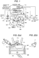
- Fig. 1 shows a schematic view of a system of an internal combustion engine on which a fuel injector 1 is mounted.
- An intake air system comprises an air flow sensor 310 for measuring an intake air amount, an electronic controlled throttle 320 for controlling the air amount, an air fluidity control valve 330 for generating a tumble in a cylinder 680, a partition plate 340 (this is called, a two stages port) for dividing a downstream passage of the air fluidity control valve 330, and an intake valve 350.
- an exhaust air system is installed successively in a downstream of an exhaust valve 400 and comprises an air-fuel ratio sensor 410, a three way catalyst 420, an exhaust air temperature sensor 430, NOx catalyst 440, and an oxygen concentration sensor 450.
- a passage 460 for circulating a part of an exhaust gas of the combustion gas is provided and restrains a discharge amount of NOx according to a recirculation of the exhaust gas.
- an EGR valve 470 for controlling a circulation amount of the exhaust gas is provided in a midway of this passage 460.
- a fuel system comprises a low pressure feed pump 510 for sucking up a fuel from a fuel tank 500, a compact type high pressure pump 520 for pressuring the low pressure fuel at once and for supplying the fuel to a fuel injector 1, and a fuel sensor 530 for measuring a fuel temperature.
- a piston 690 provided in an internal combustion engine 300 has a flat shape having no cavity, and a swirl flow 670 in a cylinder 680 is a tumble flow 670 which flows into the intake valve 350 and directs for the exhaust valve 400 and a piston 690.
- the fuel injector 1 is provided to a wall under the intake valve 350 with an angle having about 40 degrees from a horizontal plane.
- a fuel spray 100 is a deflection fuel spray having a thick fuel spray which has a wide spread angle in a direction of an ignition plug 700.
- a reference numeral 210 is a control unit 710, this control unit 710 sends signals to the electronic controlled throttle 320, the fuel injector 1, EGR valve 470, etc. under a basis of the operation information of a crank angle being an operation information of the internal combustion engine, an acceleration pedal sensor, the air-fuel sensor 310, the fuel temperature sensor 520 and various kinds sensors in the exhaust air system, and the control unit 710 controls suitably the combustion of the internal combustion engine.
- the stratification combustion is a combustion method in which under a condition in which a pressure in the cylinder 680 during a last half of a compression stroke is raised the fuel is injected and a combustible air-fuel mixture is gathered in a vicinity of the ignition plug 700 and a fuel spray is stratified and ignited.
- the combustion is carried out under the thin air-fuel ratio having about 40 degree in the cylinder 680, accordingly the fuel consumption can be improved.
- the homogenous combustion is a combustion method after the fuel is mixed homogeneously during an intake stroke the ignition is carried out. Since the fuel is injected to form the air-fuel ratio to have a stoichiometric air-fuel ratio as a whole cylinder 680, in comparison with the that of the stratification lean burn, a high output operation can be carried out.
- Fig. 2 is an enlargement view of an internal combustion engine 300, the fuel spray 100 is adopted to a flat piston engine and a relation between the tumble 670 is shown. The tumble flow is introduced into an interior portion of the fuel spray 100.
- the fuel spray 100 (A in figure) having the strong swirl force and injected to direct for the ignition plug direction or a surrounding portion of the ignition plug 700 can reach to the ignition plug 700 without the support of the tumble 670 but according to the tumble 670 the reach to the ignition plug 700 is supported and riding on the tumble 670 the fuel spray 100 can be transported to the ignition plug 700.
- the tumble 670 becomes a little as the resistance and the force for directing toward the piston 690 is restrained and since the reach to the piston 690 of the fuel spray 100 is obstructed, the fuel adhesion can be reduced.
- a part of the fuel spray having the narrow angle and the wide spread in the piston direction 690 is cut out or cut off, the entering of the air to the interior portion of the fuel spray 100 can be promoted.
- the force for directing to the piston 690 is restrained, and the reach to the piston 690 is obstructed, then the fuel adhesion can be reduced.
- Fig. 3 is a view in which a hollow cone shape fuel spray obtained by a conventional fuel injector 200 having a straight fuel injection port is injected when the pressure in the cylinder 680 is raised.
- the fuel spray is crashed and a compact fuel spray 210 having a narrow fuel spray angle is formed.
- this fuel spray is collided with the cavity of the piston and stratified, there is a merit in which the fuel spray is received in the cavity of the piston and stratified easily.
- Fig. 4 is a view showing a date relating to an installation layout. Differing to the kinds of the internal combustion engine 300, an installing angle ⁇ of the fuel injector 1 is a range of 20-40 degrees. A spark generating portion 710 of the ignition plug 700 is installed with 0 - ⁇ °(about 5 degrees) degrees against a horizontal line (a direction for crossing in a right angle the movement direction of the piston) drawn from a center of the fuel injection port of the fuel injector 1.
- An angle formed by an outer edge portion 100a of the deflection fuel spray 100 injected from the fuel injector 1 and said above stated horizontal line, namely an angle ⁇ in the ignition plug direction 700 is set lower than 10 degrees.
- a sum of these ⁇ and ⁇ is named as a deflection angle.
- the fuel spray angle injected from the fuel injector 1 is large in the ignition plug 700 side and the fuel spray angle is narrow, and further the fuel spray portion in the large fuel spray angle side is injected to direct for an opposite side to the piston 690 from the spark generation portion 710.
- the fuel spray injected from the spark generation portion 710 to direct the opposite side to the piston 690 induces the surrounding air and accordingly the air-fuel mixture having a good combustible concentration can be formed to the spark generation portion 710.
- FIG. 5 shows a measurement apparatus of the above stated fuel spray.
- a reference numeral 40 indicates a cylindrical shape fuel spray vessel and three side faces thereof optical glasses are arranged and at one side face the fuel injector 1 is installed.
- a laser irradiation means 41 generates a seat light 42 by a slit which is provided in a light generation portion and since the seat light is rotated and radiates to a longitudinal and lateral cross-section direction of the fuel spray.
- a photography use camera 43 in which an adjustment in a zoom direction and a left and right direction is capable to carry out is provided and according to a monitor 44, then the fuel spray can be observed.
- a reference numeral 45 indicates a personal micro-processor and this personal micro-processor 45 comprises an image take-in means 46 and a pulse generation portion 47 for giving an opening command to the.fuel injector 1.
- a reference numeral 48 indicates a drive circuit and a reference numeral 49 is a fuel tank which is pressurized and adjusted according to N 2 bomb 50.
- a liquid having the characteristic resembled to the gasoline is used as alternatives.
- a pressure in the vessel can be made under a reduced pressure or under an increased pressure according to a vacuum pump or the N 2 bomb.
- a main operating procedure is that a setting of an opening valve command to the fuel injector 100 ⁇ a setting of a timing of irradiating a laser seat ⁇ a setting of the laser seat position ⁇ a drive of an image take-in soft ⁇ an output of the opening valve command ⁇ an image take-in ⁇ an image preservation.
- a fuel spray direction (a deflection angle) of the deflection angle injected from the fuel injector 1 and a reach distance (a penetration) can be set most suitable to the various kinds of the internal combustion engines.
- Fig. 6 shows a combustion stability range in a case in which an injection timing is shown in a horizontal axis and an ignition timing is shown in a vertical axis.
- a combustion stability range 801 in the ignition timing where the fuel consumption becomes best is very narrow. For this reason, responding to the conditions about an individual machine difference in the fuel injectors and the time lapse change, it is difficult to stabilize the combustion.
- Fig. 7 shows an affect of the tumble fluidization in which the strength of the tumble 760 generated in the cylinder is shown in a horizontal axis and HC (the unburned hydrocarbon) and NOx are shown in the vertical axis.
- the strength of the tumble flow 670 is adjusted by an opening area of a passage in a lower side of the partition plate 340 according to an opening degree of an air fluidization control valve 330.
- Fig. 8 shows a longitudinal cross-sectional view of an electromagnetic type fuel injector 1 and using this figure a construction and an operation of the electromagnetic type fuel injector 1 will be explained.
- a magnetic circuit comprises a york 3, a core 2 having a shield body portion 2a for closing an opening end of the york 3 and a pillar shape portion 2b for extending toward a center portion of the york 3, and an anchor 4 for facing to the core 2 by spacing an air gap.
- a valve body 30 comprising the anchor 4 and a rod 5 and a ball 6 is inserted into to push under a pressure to a seat face 9 in an upstream side of a fuel injection hole 8 provided in a nozzle member 7 and for permitting a passage of the fuel and as an elastic member a hole 4A for holding a spring member 10 being as an elastic body member is provided.
- the valve body 30 is driven as one body with the anchor 4, the rod 5 and the ball 6 and between a valve seat the valve body 30 for opening and closing the fuel passage is constituted.
- an upper end of the spring member 10 is contacted to a lower end of a spring member adjuster 11 which is inserted in a center of the core 2 to adjust a set load.
- a seal ring 12 fixed mechanically to between the both is provided.
- the coil 14 for exciting the magnetic circuit is wound to a bobbin 13 and an outer periphery thereof is molded by a plastic body member.
- a terminal 17 of a coil assembly body 15 constituted by these components is inserted to a hole which is provided to a brim portion 2a of the core 2.
- the terminal 17 is combined with a terminal of the control unit not shown in figure.
- a plunger receiving portion 18 for receiving the valve body 30 is opened, and further a nozzle receiving portion 20 having a large diameter of the plunger receiving portion 18 and for receiving a stopper 19 and a nozzle portion member 7 is penetrated through until a tip end of the york 3.
- the valve body 30 comprises the magnetic material anchor 4, the rod 5 in which a tip thereof is formed integrally with the anchor 4, and the ball 6 for joined to a tip end portion of the rod 5 and a side of the anchor 4 of the rod 5 a cavity portion 5A for permitting the passing-through of the fuel is provided.
- a flow-out port 5B of the fuel is provided to the cavity portion 5A.
- valve body 30 since an outer periphery of the anchor 4 contacts to the seal ring 12, a move in the axial direction is guided and also a vicinity of the tip end of the rod 5 to which the ball 6 is joined is guided to an inner peripheral face 23 of the fuel swirl element 22 which is inserted into an inner wall 21 of a hollow portion of the nozzle member 7.
- the stroke (the movement amount to an axial upper portion in Fig. 1) of the valve body 30 is set according to a gap between a receiving face 5C of a neck portion of the rod 5 and the stopper 19. Further, a filter 24 is provided to prevent the entering of the dusts and the foreign matters in the fuel and the piping toward in a side of the valve seat to between the ball 6 and the seat face 9.
- Fig. 9 shows a fuel injector 31 having the two coils comprised of a control coil 111 and a hold coil 112 as a means for generating a drive force of the valve body 30.
- Other constructions except for the coil portion have the same function or the similar function of the fuel injector shown in Fig. 9.
- the characteristic of this fuel injector 31 is that it is driven by a battery voltage.
- the fuel can be injected to a low injection amount region with a good accuracy performance and further it has a characteristic in which a consumption electric power can be lessened.
- Fig. 10 shows an enlargement view of the electro-magnetic type fuel injector 1 or 31 and the nozzle member 7 portion and Fig. 10(a) is a longitudinal cross-sectional view of the nozzle 7 portion and Fig. 10(b) is a plane view taken from an arrow mark N direction of the nozzle member 7 portion.
- a center of the fuel injection hole 8 is coincided with an axial line J (a valve axial center) of the valve body 5 and also a wall face of the fuel injection hole 8 is formed in parallel to the axial line J (the valve axial center) of the valve body 5 and is formed with a largeness of a diameter of do.
- a L type cut-out portion (a L shape 28 cut-off portion) is constituted with faces 7A and 7B which are orthogonal with the axial line J and a face A1 with a substantially parallel to the axial line J and the face 7B and the face A1.
- the L type cut-off portion 28 is constituted by a means for restricting a force which directs for a crossing direction of the valve shaft of the fuel being injected.
- a taper face 7C succession to the face 7A is formed and this face 7C can absorb a shock sound of the valve body 5 and has a function for improving a rigidity performance.
- the "cut-off" in the cutoff face A1 etc. is limited to the processing method but it means the shape in which a part thereof is cut out, as a result it is not limited to a subject which is processed by cutting-off actually using the cutting processing etc.. Namely, it can employ a press processing (an elastic processing) using a die member or a processing using a forging processing. Further, the ball 6 is unnecessary to limit to a sphere shape, but it may employ a cone shape needle valve.
- an axial direction groove 25 in which an outer peripheral portion of the fuel swirl element 22 is formed to a flat face setting and a radial direction groove 26 are provided.
- the axial direction groove 25 is formed with the flat face but it can be formed with other shapes such as a circular passage etc..
- the above stated axial direction groove 25 and the radial direction groove 26 are the fuel passages in which the fuel is introduced from an upper portion of the fuel swirl element 22 and the fuel which has passed through the axial direction groove 25 is introduced eccentrically from an axial center in the radial direction groove 26 and the fuel is imparted the swirl and during the injection of the fuel from the fuel injection hole 8 provided on the nozzle member 7 the atomization performance in the fuel can be promoted.
- the fuel swirl element 22 is pressed and fixed under pressure to an inner peripheral face of the nozzle member 7.
- the swirl strength (a swirl number S) imparted by the fuel swirl element 22 is requested according to a following equation.
- the fuel is flown into the interior portion of the fuel injector 1 from a filter 24 and is passed through an interior portion passage of the core 2, an outer peripheral portion of the anchor 4, a cavity portion 5A which is formed in the anchor 4 and for permitting the passing-through of the fuel, and a flow-out port 5B of the fuel and reaches to the downstream.
- the fuel is passed through further a space between a stopper 19 and the rod 5, the axial direction fuel passage 25 of the fuel swirl element 22, the radial direction fuel passage 26 of the fuel swirl element 22 and is swirl-supplied to the seat portion and then the fuel is injected from the fuel injector 8 during the opening valve time.
- Fig. 4 shows a schematic manner in which the fuel is directly injected into the combustion chamber (the cylinder) of the internal combustion engine.
- the fuel spray which is injected from the fuel injector 1 of this embodiment is deflected in the side of the ignition plug 700 and the deflection angle is shown with ⁇ + ⁇ .
- the correspondence with the face of the nozzle member 7 shown in Fig. 10(b) is that a direction M shown in the figure is corresponded with the deflection direction of the fuel spray.
- the air-fuel mixture having the combustible concentration is thick but in the side of the ignition plug 700 and in the side of the piston 690 the air-fuel mixture having the combustible concentration is not existed. Namely, in the side of the piston 690, a part of the fuel spray has a cut-out shape.
- the fuel spray is determined suitably in accordance with the inner diameter of the cylinder of the internal combustion engine to be subjected, in other words in accordance with the capacity of the internal combustion engine and the installation angle of the fuel injector, in concretely it can set in accordance with the size of (L'-L) and the above stated swirl number S, etc..
- the fuel injector of this embodiment can generate the effective deflection fuel spray having the range of the swirl number of 2-7.
- the comparison condition is the condition in which the fuel spray exists in the ignition plug direction.
- the conventional fuel injector having the straight fuel injection hole if the back pressure is risen, it can not suit because the fuel spray is turned away from the ignition plug direction.
- the fuel spray exists in the ignition plug direction, although it changes a little according to the increase of the atmosphere density. Namely, according to this embodiment, since the combustible air-fuel mixture can be existed stable in the surrounding portion of the ignition plug, accordingly the combustion stability range can be enlarged.
- a fuel injector in which a nozzle portion is formed thin and long.
- this fuel injector is mounted on the internal combustion engine, there is a saving space, since the fuel injector can provide to not interfere another components and the cylinder head, there is a merit in which a freedom degree for installing the fuel injector can be heightened.
- this structure has the merit in which at least one selected from a low cost performance according to a simplification performance of the components and a low cost material utilization, a sure fuel seal, a high accuracy of the fuel injection amount characteristic, a high efficiency performance of the magnetic circuit, and a secondary fuel injection prevention etc. can be responded.
- Fig. 13 is a longitudinal cross-sectional view of a fuel injector 60.
- a hollow shape core 66 In this fuel injector 60, from a center to an outer shape direction a hollow shape core 66, a nozzle holder 69, a coil 68, a yoke 67 are arranged, to the nozzle holder 69 a plunger 80 having a valve body is mounted in an interior portion thereof, and this plunger 80 is forced to a side of an orifice plate 71.
- An outer diameter of a hollow cylindrical portion 66a of the core 66 is formed larger than an inner diameter of a thin diameter portion of the nozzle holder 69.
- this fuel injector 60 As to a basic operation of this fuel injector 60, when the coil 68 is applied with the electric current, the yoke 67, the core 66, an anchor 74 (a part of the plunger 80) and a portion sandwiched by the anchor 74 of the nozzle holder 69 and the core 66 form the magnetic circuit, in accordance with this magnetic circuit since the plunger 80 is attracted against a force of a return spring member 65, an opening valve operation is carried out.
- a lower end face of the core 66 works a role of a stopper for receiving the plunger 80 during the opening valve operation time. For this reason, to the lower end face of the core 66 and an upper end face of the anchor 74 it is preferable to carry out the electrolyte plating manner such as a chrome plating.
- the core 66 is comprised of a hollow cylindrical portion 66a and a hollow disc portion 66b as one body.
- the core 66 can be performed according to a press processing of a magnetic material (an electro-magnetic stainless) of a stainless group and a cutting processing.
- a diameter of the hollow cylindrical portion 66a of the core 66 is larger than an inner diameter of the thin diameter portion of the nozzle holder 69.
- a fuel connector 63 is welded.
- An end face of a side of the core 66 of a connector pipe 63 has an enlarged structure and a welding margin can be obtained fully.
- this welding is carried out on one periphery of a joining boundary portion, for example portions shown with reference numerals 66a and 66c, according to a laser welding etc..
- this pipe 63 has a step-wise difference in which a fuel filter 77 for removing the dusts etc. which are mingled with the fuel from an upstream side of the fuel passage, a spring press member 64 for regulating an initial load of the return spring member 65 are inserted and fixed.
- the above stated step-wise difference can be formed with a low cost according to a pipe squeeze processing.
- the fuel pipe connector 63 is constituted separately with the core 66, this connector 3 can be altered with the various coupling structures.
- the nozzle holder 69 is made from the magnetic material of the stainless (the electro-magnetic stainless).
- the pipe member has the thin and long nozzle portions (from 69a to 69d) and has a step-wise difference of the anchor/core supports (from 69f to 69j) which has the inner diameter larger than the inner diameter of the nozzle portion and is along to an outer diameter of the cylindrical portion 66a of the core 66.
- the nozzle holder 69 is performed integrally according to the pipe squeeze processing and can be manufactured with the low cost compared with the cutting processing.
- the orifice plate 71 and the fuel swirl element 72 are provided, and they are formed with separate members.
- a Teflon seal 70 for performing the combustion gas seal is provided.
- This seal 70 has a step-wise formation portion 69e for connecting the thin diameter nozzle portions (from 69a to 69d) and the anchor/core support portions (from 69f to 69j).
- an angle to an axial direction of the step-wise formation portion 69e is substantially 90 degrees, however it is not limited to this but any angle can be employed.
- the plunger 80 is constituted by a plunger rod 73, the anchor 74 and joint pipes 78 for joining the respective components. Further, between the joint pipe 78 and the anchor 74, a ring shape plate spring member 75 is sandwich-mounted.
- the joint pipe 78 is formed according to the pipe squeeze processing. The joint pipe 78 is inserted under pressure to the plunger rod 73 and fixed according to the laser welding manner.
- the anchor 74 has a hollow structure and the plate spring member 75 is formed with the ring shape and an inner side thereof is a punching portion. Further, to the joint pipe 78, the fuel passage hole is opened. To the plate spring member 75, one end of a mass ring 76 being a cylindrical shape movable mass body is received.
- the mass ring 76 is formed, for example, by a non-magnetic material of stainless material to prevent the magnetic short-circuit formed between the core 66 and the anchor 74.
- the mass ring 76 is positioned extending over one end of an inner periphery of the core 66 and one end of an inner periphery of the anchor 74.
- a hollow hole formed in the core 66 becomes the fuel passage and to the hollow hole from the lower portion in turn the mass ring 76, a return spring member 65 are arranged. Further, in the fuel connector pipe 63, a spring pressing ember 64 for regulating an initial load of the return spring member 65 and the fuel filter 77 are provided in turn.
- the mass ring 76 is intervened movably independently between the return spring member 76 and the plunger 80 in the axial direction. To compensate the independent movable move, between the mass ring 76 and the plunger 80, the plate spring member 75 is intervened and according to the plate spring member 75 the mass ring 76 is received. As stated in above, the mass ring 76 works a role to carry out a dynamic damper action for restraining a backlash operation of the plunger 80 during the closing valve operation time.
- This damper action is that during the closing valve time of the plunger 80 when the plunger 80 collides with the valve seat 78 according to the force of the return spring member 65, the plunger 80 is carried out the backlash but the kinetic energy at this time is absorbed through the inertia of the mass ring 76 and an elastic deformation of the plate spring member 75 and the backlash is attenuated. This damper action can bring out an extremely action effect.
- Fig. 14 is an enlargement cross-sectional view of a vicinity portion of the tip end of the nozzle holder 69 and referring to this figure the generation method and the manufacture method of the deflection fuel spray of the fuel injector according to the present invention will be explained.
- the orifice plate 71 and the fuel swirl element 72 are provided and they are constituted using separated members.
- the orifice plate 71 for example, is formed with a stainless group disc chip and to a center thereof the fuel injection hole (an orifice) is provided and to an upstream portion succession to this the valve seat 78 is formed.
- the orifice plate 71 is installed under pressure to the tip end 69a of the nozzle holder 69.
- the fuel swirl element 72 is inserted under pressure to the tip end 69a of the nozzle holder 69 according to the space fit-into manner and is formed with a sintering alloy such as SUS 416.
- This fuel swirl element 72 is a tip shape near to a substantial disc and at a center thereof a central hole (a guide) 81 for slide-guiding a tip end 73a of the plunger rod 73 is provided and further extending over from an upper face to a lower face a vertical passage 82 for guiding the fuel to the outer periphery is provided.
- a ring shape step-wise difference (a flow passage) 83 is formed to the outer peripheral edge and between this ring shape passage 83 and the central hole 81, plural offset passages for forming the swirl flow of the fuel, for example from four to six, are formed.
- a swirl chamber 85 is formed to obtain stable the swirl flow of the fuel. Further, after the insertion under pressure of the fuel swirl element 72 by pressing the orifice plate 71, the orifice plate 71 is welded and fixed.
- This welding is carried out extending over one periphery of a combined boundary portion according to the laser welding manner etc. to hold the fuel seal performance. Further, to the offset passage 84 of the fuel swirl element 72, a part (a part of the row material) of the side of the orifice plate 71 is rounded in and a rotation dent is carried out surely.
- a L shape cut-off portion 86 for generating the deflection fuel spray is formed.
- the position of the cut-off portion is provided to a portion which coincides substantially with a central position of the fuel injection hole 79.
- a detail formation method of the cut-off portion will be similar to that of the method explained in Fig. 10.
- an outlet end of the fuel injection hole 79 is constituted with a projection shape 87 and this is formed by a structure in which the rigidity performance is heightened and a shock sound when the tip end 73a of the plunger rod 73 to the valve seat can be attenuated.
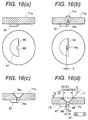
- Fig. 15 and Fig. 16 show one example of forming the method of the orifice plate 71
- Fig. 15 shows a processing flow-chart
- Fig. 16 shows a figure after the formation through the respective processes.
- (a) Through a cold forging processing the outer form 71a of the orifice plate 71 is formed.
- a substantially concentrically semi-circular shape wall 88 is provided in a corresponding portion of the fuel injection hole formation portion and has a larger diameter than the diameter of the fuel injection hole.
- the fuel injection hole 79 is formed.
- the fuel injection hole 79 is formed concentrically through a gap ⁇ with the above stated wall 88. Further, this fuel injection hole 79 is not punched out but formed with a voluntary depth part.
- a raised portion 71 is formed.
- the gap ⁇ is several 10 ⁇ m degree.
- the valve seat for forming a seat portion is formed a cut-off processing etc..
- the processing portion is the above stated raised portion 71b and this portion is taken off.
- the finishing of the essential portion for example, the seat face 78 and the fuel injection hole 79 etc. is carried out.
- Fig. 17 shows a modified example of the orifice plate 71.
- the carrying-out embodiment shown in (a) and (b) is a case in which a wall face 90 for constituting a L shape cut-off face is formed longer and remote from the fuel injection hole 79. Further, the carrying-out embodiment shown in (c) and (d) is a case in which after the face wall 91 has been extended from the fuel injection hole 79 in the same axial direction and a part of the wall is removed with a recessed portion 92.
- Fig. 18 shows an embodiment of a divisional construction of the orifice plate. This figure is an enlarged cross-sectional view of a vicinity portion of the tip end of the nozzle holder 69.
- An orifice plate 93 is formed, for example, with a stainless group disc shape chip and at a center thereof a fuel injection hole 95 (the orifice) is provided, and to an upstream portion succession to this a valve seat 94 is formed.
- the orifice plate 93 is installed under pressure to the tip end 69a of the nozzle holder 69.
- a fuel spray formation use plate 96 which corresponds to a L shape cut-off is provided.
- a semi-circular shape hole 97 is formed according to the punching-out etc. and a wall 97a being concentical to the fuel injection hole 95 and a wall 97b for coinciding substantially with an axial center of the fuel injection hole 95 are provided.
- Fig. 19 shows a carrying-out embodiment in which a nozzle tip end face is adopted to a cone shape fuel injector.
- a fuel injector hole 152 positioned in an end face of a cone shape 151 portion which is positioned in a tip end portion of a nozzle 140.
- a L shape cut-off which is comprised of a wall 154a positioned substantially to a center of the fuel injection hole 152 and a substantially orthogonal to a wall 154b which is cut off with a voluntary depth is formed.
- a fuel swirl element 156 is fixed under pressure by utilizing a nozzle inner wall 150a.
- the fuel is passed through and then the swirl fuel is generated and the fuel is injected from the fuel injection hole 152.
- the deflection fuel spray is generated suitably according to the cut-off.
- Fig. 20 is a carrying-out embodiment of a structure in which a fuel swirl element is divided into two.
- a fuel swirl member comprised of a fuel plate 166 having plural vertical passages 166a and a swirl plate 167 having plural swirl passages 167a is inserted, an orifice plate 161 is inserted and fixed by contacting a lower face of the fuel swirl member.
- a fuel injection hole 162 succession to a valve seat face 163 is provided, to this fuel injection hole 162 portion a L shape cut-off which is comprised of a wall 164a positioned substantially to a center of the fuel injection hole 162 and a substantially orthogonal to a wall 164b which is cut off with a voluntary depth is formed.
- Fig. 21 shows an adoption example to the internal combustion engine having a piston which has a tumble flow preservation cavity.
- An internal combustion engine 800 has a piston 810 which has a shallow dish shape cavity 820 and with this piston 810 a tumble 670 is preserved, a fuel adhesion to a side of piston 810 of the deflection fuel spray 100 can be restrained, and also the fuel spray fluidization to the ignition plug direction 700 can be assisted and the combustible air-fuel mixture is introduced suitably to the ignition plug 700. With this, HC discharge amount can be restrained and the stable combustion can be carried out.
- Fig. 22 shows an adoption example to an internal combustion engine having a piston which has two cavities for guiding the tumble flow preservation use and the fuel spray.
- An internal combustion engine 850 has a piston 890 which has two cavities which are a tumble 860 guiding use cavity 870 and a fuel spray guiding use cavity 880.
- the fuel spray fluidization to the ignition plug 700 direction can be assisted, the fuel spray is guided and the combustible air-fuel mixture can be introduced stable. Accordingly the stable combustion can be carried out.
- the fuel is injected by diving plural times during the intake stroke, and then the penetration of the fuel spray is restrained and further the fuel adhesion to the wall face of the cylinder 680 at the exhaust side and the crest face of the piston 810 can be restrained.
- the fuel is injected with the plural times during the compression stroke and the fuel spray is guided by the tumble 820 and then the stable combustion according to the stratification combustion can be realized.
- the fuel spray embodiment shown in the figure shows the manner during the low load and the low rotation in which the fuel spray 100a injected with the first time is stayed in the surrounding portion of the ignition plug 700, after that before long the fuel spray 100b is caught up, as a result to the surrounding portion of the ignition plug 700, the combustible air-fuel mixture stays during the long period, the stable combustion in the area in which in any internal combustion engine the stratification combustion is difficult can be realized.
- Fig. 24 shows views in which (a) is an explanatory view of a wiring of a drive circuit 400 of the fuel injector 31 used in the above stated tests and (b) is an explanatory of a drive current wave-form.
- a battery voltage is supplied from a battery VB and in accordance with a control signal from an engine controller 41, the electric supply control for the control coil 111 and the hold coil 112 is carried out.
- a hold coil transistor ON/OFF circuit 104 for carrying out the electric supply control of the hold coil 112 and a control coil transistor ON/OFF circuit 114 for carrying out the electric supply control of the control coil 111 are provided.
- the respective transistor ON/OFF circuits has the electric current information to the respective coils 111 and 112 which is detected by a hold coil current detection resistor 103R and a control coil current detection resistance 113R.
- the respective transistor ON/OFF circuits sends an electric supply signal to a hold coil use power transistor 102t and a control coil use power transistor 112t.
- Reference numerals 101R and 111R are equivalent circuits of the interior resistances and drive circuits of the hold coil 112 and the control coil 111.
- the hold coil 112 and the control coil 111 have respectively a different electric characteristic.
- the hold coil 112 and the control coil 111 have a different role in the respective stages of the closing valve, the opening valve, the opening valve hold, and the closing valve.
- the control coil 111 in this embodiment, is a coil which is used exclusively in an opening valve initial condition and the hold coil 112 is a coil which is used in a closing holding condition.
- a winding diameter of the control coil 111 is a bold wiring structure having a small resistance rate.
- the power transistor 112t is formed with a bipolar, CMOS or bi-CMOS and "ON" resistance during the electric supply is reduced, the equivalent interior resistance 111R of the control coil circuit is reduced.
- the winding number is made the vicinity in which a reach magneto-motive force is the maximum.
- the electric supply start to the hold coil 112 is unnecessary at the same time of the fuel injection signal input and it is sufficient with the late time thereof.
- a reach current of a fuel injection rise-up time of the hold coil 112 can be lower from a case in which the electric supply starts at the same time of the fuel injection signal.
- the fuel injection apparatus constituted as stated in above operates as following.
- ECU 41 output to the drive circuit 400 a command Tg of plural time injections in accordance with the operation conditions of the internal combustion engine.
- Tg a command of plural time injections in accordance with the operation conditions of the internal combustion engine.
- the control coil use transistor 112t and the hold coil use transistor 102t are presented to "ON" state.
- a total current viewed from the battery is shown with a bold line of a lower side figure of Fig. 24(b).
- the transistor 102t is made to present "OFF" state after it lapses the time t2.
- the transistor 102t is controlled during the first fuel injection period T2 all the time.
- the valve which has opened by a sum of the holding force of the both coils is maintained to form the opening valve state by the magneto-motive force of the control coil 111.
- the fuel is passed through the fuel swirl element 22 and is injected into the combustion chamber from the fuel injection hole.
- a total current viewed from the battery is shown with a bold line of a lower side figure (left) of Fig. 24(b).
- the transistor 112t is made to present "OFF" state after it lapses the time t2.
- the transistor 112t is controlled to present "OFF" state during the second fuel injection period T3 all the time.
- the valve which has opened by a sum of the magneto-motive force of the both coils is maintained to form the opening valve state by the holding force of the control coil 111.
- the fuel is passed through the fuel swirl element 22 and is injected into the combustion chamber from the fuel injection hole.
- the fuel injector in regardless the fuel injector drives with the high speed, the fuel injector can be driven with the power supply voltage. Further, after the closing valve since it holds the slight holding current, at this during this one fuel injection timing two times or more than two times the fuel injector is opened and closed and then the electric power consumption can be lessened.
- the fuel injector can be made compact.
- Fig. 25 shows the effects according to the two times fuel injection with the combustion stability range.
- This figure shows the combustion stability range compared with the first embodiment according to the present invention by taking in the horizontal axis the fuel injection timing and in the horizontal axis the ignition timing.
- the combustion stability range 900 of the first embodiment which becomes wide extremely compared with the conventional internal combustion engine, since two times fuel injection is carried out, since the combustible air-fuel mixture is stayed in the surrounding portion of the ignition plug ranging over in the long period, the combustible stable range 910 is made wide further.
- the stable combustion can be carried out in regardless the engine rotation number and the fuel consumption can be improved further.
- the good ignition performance of the internal combustion engine can be obtained, and the enlargement in the combustion stability range can be improved and also the discharge amount of the unburned gas components in the combustion can be reduced.
Landscapes
- Engineering & Computer Science (AREA)
- Chemical & Material Sciences (AREA)
- Combustion & Propulsion (AREA)
- Mechanical Engineering (AREA)
- General Engineering & Computer Science (AREA)
- Physics & Mathematics (AREA)
- Electromagnetism (AREA)
- Fuel-Injection Apparatus (AREA)
- Ignition Installations For Internal Combustion Engines (AREA)
- Combustion Methods Of Internal-Combustion Engines (AREA)
- Exhaust-Gas Circulating Devices (AREA)
Applications Claiming Priority (2)
| Application Number | Priority Date | Filing Date | Title |
|---|---|---|---|
| JP2000286854A JP4193346B2 (ja) | 2000-09-18 | 2000-09-18 | 内燃機関 |
| JP2000286854 | 2000-09-18 |
Publications (2)
| Publication Number | Publication Date |
|---|---|
| EP1188920A2 true EP1188920A2 (fr) | 2002-03-20 |
| EP1188920A3 EP1188920A3 (fr) | 2003-04-16 |
Family
ID=18770712
Family Applications (1)
| Application Number | Title | Priority Date | Filing Date |
|---|---|---|---|
| EP01121712A Withdrawn EP1188920A3 (fr) | 2000-09-18 | 2001-09-17 | Moteur à combustion interne |
Country Status (3)
| Country | Link |
|---|---|
| US (1) | US6668793B2 (fr) |
| EP (1) | EP1188920A3 (fr) |
| JP (1) | JP4193346B2 (fr) |
Cited By (3)
| Publication number | Priority date | Publication date | Assignee | Title |
|---|---|---|---|---|
| EP1327771A2 (fr) * | 2001-12-27 | 2003-07-16 | Hitachi, Ltd. | Soupape d'injection avec corps de buse |
| EP1281859A3 (fr) * | 2001-08-03 | 2003-11-19 | Hitachi, Ltd. | Injecteur de combustible électronique |
| EP2749762B1 (fr) * | 2011-08-22 | 2017-03-22 | Toyota Jidosha Kabushiki Kaisha | Soupape d'injection de carburant |
Families Citing this family (9)
| Publication number | Priority date | Publication date | Assignee | Title |
|---|---|---|---|---|
| JP4055360B2 (ja) * | 2000-12-26 | 2008-03-05 | 株式会社日立製作所 | 燃料噴射弁 |
| JP2004036554A (ja) * | 2002-07-05 | 2004-02-05 | Hitachi Ltd | 燃料噴射装置,内燃機関及び燃料噴射装置の制御方法 |
| JP2005248857A (ja) * | 2004-03-04 | 2005-09-15 | Mitsubishi Electric Corp | 内燃機関の燃焼制御装置 |
| JP4941664B2 (ja) * | 2007-09-27 | 2012-05-30 | 三菱自動車工業株式会社 | 筒内噴射型内燃機関 |
| US8431836B2 (en) * | 2008-11-06 | 2013-04-30 | Miretti SpA | Connector apparatus and system for explosion proof engine |
| DE102009015528B4 (de) * | 2009-04-02 | 2021-08-12 | Man Energy Solutions Se | Ventileinheit einer Kraftstoffversorgungsanlage |
| US8351780B2 (en) * | 2011-02-01 | 2013-01-08 | Hamilton Sundstrand Corporation | Imaging system for hollow cone spray |
| JP2014070530A (ja) * | 2012-09-28 | 2014-04-21 | Daihatsu Motor Co Ltd | 内燃機関 |
| DE102019104294A1 (de) * | 2018-03-15 | 2019-09-19 | Denso Corporation | Korrosionsbeständige Vorrichtung |
Citations (2)
| Publication number | Priority date | Publication date | Assignee | Title |
|---|---|---|---|---|
| JPH0681651A (ja) | 1992-02-28 | 1994-03-22 | Mitsubishi Motors Corp | 筒内噴射型内燃機関 |
| JPH0681656A (ja) | 1992-09-02 | 1994-03-22 | Nissan Motor Co Ltd | ガソリンエンジン |
Family Cites Families (9)
| Publication number | Priority date | Publication date | Assignee | Title |
|---|---|---|---|---|
| DE3690388T1 (fr) * | 1985-07-19 | 1987-07-16 | ||
| US4844030A (en) * | 1985-12-12 | 1989-07-04 | Cummins Engine Company, Inc. | Thermal fatigue resistant cylinder head |
| US5392745A (en) * | 1987-02-20 | 1995-02-28 | Servojet Electric Systems, Ltd. | Expanding cloud fuel injecting system |
| US5577481A (en) * | 1995-12-26 | 1996-11-26 | General Motors Corporation | Fuel injector |
| JPH10281039A (ja) * | 1997-04-02 | 1998-10-20 | Hitachi Ltd | 燃料噴射装置とその制御方法 |
| JP3325232B2 (ja) * | 1997-09-29 | 2002-09-17 | マツダ株式会社 | 筒内噴射式エンジン |
| JP3771361B2 (ja) * | 1997-11-26 | 2006-04-26 | 株式会社日立製作所 | 燃料噴射弁 |
| JP3932697B2 (ja) * | 1998-10-01 | 2007-06-20 | 株式会社日立製作所 | 筒内噴射型内燃機関の燃料噴射方法および、燃料噴射弁,内燃機関,燃焼方法 |
| JP4055315B2 (ja) * | 1999-03-17 | 2008-03-05 | 株式会社日立製作所 | 燃料噴射弁およびこれを搭載した内燃機関 |
-
2000
- 2000-09-18 JP JP2000286854A patent/JP4193346B2/ja not_active Expired - Fee Related
-
2001
- 2001-09-17 EP EP01121712A patent/EP1188920A3/fr not_active Withdrawn
- 2001-09-18 US US09/954,268 patent/US6668793B2/en not_active Expired - Fee Related
Patent Citations (2)
| Publication number | Priority date | Publication date | Assignee | Title |
|---|---|---|---|---|
| JPH0681651A (ja) | 1992-02-28 | 1994-03-22 | Mitsubishi Motors Corp | 筒内噴射型内燃機関 |
| JPH0681656A (ja) | 1992-09-02 | 1994-03-22 | Nissan Motor Co Ltd | ガソリンエンジン |
Cited By (7)
| Publication number | Priority date | Publication date | Assignee | Title |
|---|---|---|---|---|
| EP1281859A3 (fr) * | 2001-08-03 | 2003-11-19 | Hitachi, Ltd. | Injecteur de combustible électronique |
| US6918548B2 (en) | 2001-08-03 | 2005-07-19 | Hitachi, Ltd. | Electronic fuel injector |
| EP1327771A2 (fr) * | 2001-12-27 | 2003-07-16 | Hitachi, Ltd. | Soupape d'injection avec corps de buse |
| EP1327771A3 (fr) * | 2001-12-27 | 2003-08-06 | Hitachi, Ltd. | Soupape d'injection avec corps de buse |
| US6845748B2 (en) | 2001-12-27 | 2005-01-25 | Hitachi, Ltd. | Fuel injection valve and its apparatus, method for manufacturing internal combustion engine and fuel injection valve and its nozzle body, and method for manufacturing the same |
| US7124735B2 (en) | 2001-12-27 | 2006-10-24 | Hitachi, Ltd. | Fuel injection valve and its apparatus, method for manufacturing internal combustion engine and fuel injection valve and its nozzle body, and method for manufacturing the same |
| EP2749762B1 (fr) * | 2011-08-22 | 2017-03-22 | Toyota Jidosha Kabushiki Kaisha | Soupape d'injection de carburant |
Also Published As
| Publication number | Publication date |
|---|---|
| US6668793B2 (en) | 2003-12-30 |
| EP1188920A3 (fr) | 2003-04-16 |
| JP2002089269A (ja) | 2002-03-27 |
| US20020050267A1 (en) | 2002-05-02 |
| JP4193346B2 (ja) | 2008-12-10 |
Similar Documents
| Publication | Publication Date | Title |
|---|---|---|
| US6588399B2 (en) | Fuel injection method of internal combustion engine and fuel injection apparatus of internal combustion engine | |
| JP3671785B2 (ja) | 筒内噴射型内燃機関の燃料噴射装置 | |
| EP1571330B1 (fr) | Injecteur de combustible | |
| EP1188920A2 (fr) | Moteur à combustion interne | |
| EP1389679A1 (fr) | Moteur thermique a allumage par compression | |
| US20060191511A1 (en) | Fuel injector and in-cylinder direct-injection gasoline engine | |
| JP2000097129A (ja) | 電磁式燃料噴射弁 | |
| JP2587071B2 (ja) | 燃料噴射弁 | |
| JP2004036554A (ja) | 燃料噴射装置,内燃機関及び燃料噴射装置の制御方法 | |
| US7082921B2 (en) | Fuel injection valve and direct-injection engine with the same | |
| US11136954B2 (en) | Fuel injection valve | |
| WO2004109096A1 (fr) | Reduction des emissions d'hydrocarbures au moyen de la regulation du motif de pulverisation par la commande de pression de carburant dans des systemes a injection de carburant | |
| JP3847558B2 (ja) | 内燃機関の燃料噴射装置 | |
| JP4349374B2 (ja) | 筒内噴射型内燃機関 | |
| JP5274701B1 (ja) | 筒内噴射式内燃機関の制御装置 | |
| JP2004514835A (ja) | 燃料噴射弁 | |
| WO2018221076A1 (fr) | Soupape d'injection de carburant et système de moteur | |
| JP2004511703A (ja) | 燃料噴射弁 | |
| JP3734924B2 (ja) | エンジンの燃料噴射弁 | |
| JP2002130085A (ja) | 燃料噴射弁及びその製作方法と内燃機関 | |
| JP7187341B2 (ja) | 燃料噴射装置および制御装置 | |
| US11143131B2 (en) | Vehicle control device | |
| JP3044876B2 (ja) | 内燃機関用電子制御燃料噴射装置 | |
| JP2001317434A (ja) | 内燃機関の燃料噴射方法および燃料噴射装置 | |
| JP3183027B2 (ja) | 電子制御エアアシスト噴射弁 |
Legal Events
| Date | Code | Title | Description |
|---|---|---|---|
| PUAI | Public reference made under article 153(3) epc to a published international application that has entered the european phase |
Free format text: ORIGINAL CODE: 0009012 |
|
| AK | Designated contracting states |
Kind code of ref document: A2 Designated state(s): AT BE CH CY DE DK ES FI FR GB GR IE IT LI LU MC NL PT SE TR |
|
| AX | Request for extension of the european patent |
Free format text: AL;LT;LV;MK;RO;SI |
|
| RIN1 | Information on inventor provided before grant (corrected) |
Inventor name: ISHIKAWA, TORU Inventor name: FUJII, HIROSHI Inventor name: KUBO, HIROMASA Inventor name: TOGASHI, SHIGENORI Inventor name: ABE, MOTOYUKI Inventor name: KADOMUKAI, YUZO Inventor name: MIYAJIMA, AYUMU Inventor name: OKAMOTO, YOSHIO |
|
| PUAL | Search report despatched |
Free format text: ORIGINAL CODE: 0009013 |
|
| AK | Designated contracting states |
Designated state(s): AT BE CH CY DE DK ES FI FR GB GR IE IT LI LU MC NL PT SE TR |
|
| AX | Request for extension of the european patent |
Extension state: AL LT LV MK RO SI |
|
| 17P | Request for examination filed |
Effective date: 20030813 |
|
| AKX | Designation fees paid |
Designated state(s): DE FR GB IT |
|
| 17Q | First examination report despatched |
Effective date: 20050622 |
|
| GRAP | Despatch of communication of intention to grant a patent |
Free format text: ORIGINAL CODE: EPIDOSNIGR1 |
|
| STAA | Information on the status of an ep patent application or granted ep patent |
Free format text: STATUS: THE APPLICATION IS DEEMED TO BE WITHDRAWN |
|
| 18D | Application deemed to be withdrawn |
Effective date: 20091225 |