EP1188492B1 - Cleaning sponge roller - Google Patents
Cleaning sponge roller Download PDFInfo
- Publication number
- EP1188492B1 EP1188492B1 EP00901955A EP00901955A EP1188492B1 EP 1188492 B1 EP1188492 B1 EP 1188492B1 EP 00901955 A EP00901955 A EP 00901955A EP 00901955 A EP00901955 A EP 00901955A EP 1188492 B1 EP1188492 B1 EP 1188492B1
- Authority
- EP
- European Patent Office
- Prior art keywords
- projection
- base portion
- roller body
- sponge roller
- cleaning
- Prior art date
- Legal status (The legal status is an assumption and is not a legal conclusion. Google has not performed a legal analysis and makes no representation as to the accuracy of the status listed.)
- Expired - Lifetime
Links
- 238000004140 cleaning Methods 0.000 title claims description 37
- 230000002093 peripheral effect Effects 0.000 claims description 25
- 239000000463 material Substances 0.000 claims description 17
- 238000005304 joining Methods 0.000 claims description 4
- 239000010419 fine particle Substances 0.000 claims description 3
- 238000009991 scouring Methods 0.000 claims description 2
- 239000000203 mixture Substances 0.000 description 16
- 239000007788 liquid Substances 0.000 description 13
- 238000000034 method Methods 0.000 description 10
- 230000001680 brushing effect Effects 0.000 description 8
- 238000004519 manufacturing process Methods 0.000 description 8
- 239000011148 porous material Substances 0.000 description 6
- XLYOFNOQVPJJNP-UHFFFAOYSA-N water Substances O XLYOFNOQVPJJNP-UHFFFAOYSA-N 0.000 description 6
- XUIMIQQOPSSXEZ-UHFFFAOYSA-N Silicon Chemical compound [Si] XUIMIQQOPSSXEZ-UHFFFAOYSA-N 0.000 description 5
- 238000005498 polishing Methods 0.000 description 5
- 229910052710 silicon Inorganic materials 0.000 description 5
- 239000010703 silicon Substances 0.000 description 5
- 235000012431 wafers Nutrition 0.000 description 5
- MHAJPDPJQMAIIY-UHFFFAOYSA-N Hydrogen peroxide Chemical compound OO MHAJPDPJQMAIIY-UHFFFAOYSA-N 0.000 description 4
- 239000006061 abrasive grain Substances 0.000 description 4
- 238000004891 communication Methods 0.000 description 4
- DHKHKXVYLBGOIT-UHFFFAOYSA-N acetaldehyde Diethyl Acetal Natural products CCOC(C)OCC DHKHKXVYLBGOIT-UHFFFAOYSA-N 0.000 description 3
- 125000002777 acetyl group Chemical class [H]C([H])([H])C(*)=O 0.000 description 3
- 238000005201 scrubbing Methods 0.000 description 3
- 229920002554 vinyl polymer Polymers 0.000 description 3
- VEXZGXHMUGYJMC-UHFFFAOYSA-N Hydrochloric acid Chemical compound Cl VEXZGXHMUGYJMC-UHFFFAOYSA-N 0.000 description 2
- 238000005520 cutting process Methods 0.000 description 2
- QSHDDOUJBYECFT-UHFFFAOYSA-N mercury Chemical compound [Hg] QSHDDOUJBYECFT-UHFFFAOYSA-N 0.000 description 2
- 229910052753 mercury Inorganic materials 0.000 description 2
- 239000002994 raw material Substances 0.000 description 2
- 239000004065 semiconductor Substances 0.000 description 2
- 239000000758 substrate Substances 0.000 description 2
- VHUUQVKOLVNVRT-UHFFFAOYSA-N Ammonium hydroxide Chemical compound [NH4+].[OH-] VHUUQVKOLVNVRT-UHFFFAOYSA-N 0.000 description 1
- KRHYYFGTRYWZRS-UHFFFAOYSA-N Fluorane Chemical compound F KRHYYFGTRYWZRS-UHFFFAOYSA-N 0.000 description 1
- VYPSYNLAJGMNEJ-UHFFFAOYSA-N Silicium dioxide Chemical compound O=[Si]=O VYPSYNLAJGMNEJ-UHFFFAOYSA-N 0.000 description 1
- 229920002472 Starch Polymers 0.000 description 1
- 238000005299 abrasion Methods 0.000 description 1
- 238000010521 absorption reaction Methods 0.000 description 1
- 239000002253 acid Substances 0.000 description 1
- XAGFODPZIPBFFR-UHFFFAOYSA-N aluminium Chemical compound [Al] XAGFODPZIPBFFR-UHFFFAOYSA-N 0.000 description 1
- 229910052782 aluminium Inorganic materials 0.000 description 1
- PNEYBMLMFCGWSK-UHFFFAOYSA-N aluminium oxide Inorganic materials [O-2].[O-2].[O-2].[Al+3].[Al+3] PNEYBMLMFCGWSK-UHFFFAOYSA-N 0.000 description 1
- QGZKDVFQNNGYKY-UHFFFAOYSA-N ammonia Natural products N QGZKDVFQNNGYKY-UHFFFAOYSA-N 0.000 description 1
- 239000007864 aqueous solution Substances 0.000 description 1
- 238000005266 casting Methods 0.000 description 1
- 239000003054 catalyst Substances 0.000 description 1
- CETPSERCERDGAM-UHFFFAOYSA-N ceric oxide Chemical compound O=[Ce]=O CETPSERCERDGAM-UHFFFAOYSA-N 0.000 description 1
- 229910000422 cerium(IV) oxide Inorganic materials 0.000 description 1
- 230000006835 compression Effects 0.000 description 1
- 238000007906 compression Methods 0.000 description 1
- 238000010276 construction Methods 0.000 description 1
- 239000003431 cross linking reagent Substances 0.000 description 1
- 230000000694 effects Effects 0.000 description 1
- 239000013013 elastic material Substances 0.000 description 1
- 238000005516 engineering process Methods 0.000 description 1
- 125000002485 formyl group Chemical class [H]C(*)=O 0.000 description 1
- 239000011521 glass Substances 0.000 description 1
- 229960002050 hydrofluoric acid Drugs 0.000 description 1
- 229910052500 inorganic mineral Inorganic materials 0.000 description 1
- 239000011707 mineral Substances 0.000 description 1
- 238000000465 moulding Methods 0.000 description 1
- 238000006116 polymerization reaction Methods 0.000 description 1
- 229920002451 polyvinyl alcohol Polymers 0.000 description 1
- 235000019422 polyvinyl alcohol Nutrition 0.000 description 1
- 238000002459 porosimetry Methods 0.000 description 1
- 235000019353 potassium silicate Nutrition 0.000 description 1
- 238000007127 saponification reaction Methods 0.000 description 1
- 238000007493 shaping process Methods 0.000 description 1
- 229910052814 silicon oxide Inorganic materials 0.000 description 1
- 239000008107 starch Substances 0.000 description 1
- 235000019698 starch Nutrition 0.000 description 1
- 239000002344 surface layer Substances 0.000 description 1
- 238000007514 turning Methods 0.000 description 1
Images


Classifications
-
- B—PERFORMING OPERATIONS; TRANSPORTING
- B08—CLEANING
- B08B—CLEANING IN GENERAL; PREVENTION OF FOULING IN GENERAL
- B08B1/00—Cleaning by methods involving the use of tools
- B08B1/30—Cleaning by methods involving the use of tools by movement of cleaning members over a surface
- B08B1/32—Cleaning by methods involving the use of tools by movement of cleaning members over a surface using rotary cleaning members
- B08B1/34—Cleaning by methods involving the use of tools by movement of cleaning members over a surface using rotary cleaning members rotating about an axis parallel to the surface
-
- B—PERFORMING OPERATIONS; TRANSPORTING
- B08—CLEANING
- B08B—CLEANING IN GENERAL; PREVENTION OF FOULING IN GENERAL
- B08B1/00—Cleaning by methods involving the use of tools
- B08B1/10—Cleaning by methods involving the use of tools characterised by the type of cleaning tool
- B08B1/16—Rigid blades, e.g. scrapers; Flexible blades, e.g. wipers
Definitions
- the present invention relates to a cleaning sponge roller capable of scrubbing fine particles off extremely efficiently, such as abrasive grains, cutting dusts, polishing dusts adhered to the surface of an object to be cleaned after a working process such as polishing in a process of manufacturing aluminum disks for magnetic recording, substrates of semiconductor silicon wafers and the like without damaging the surface of an object to be cleaned.
- polishing In a process of producing hard disks, glass disks, silicon wafers, semiconductor devices during a CMP process, photo masks, liquid glass substrates, etc., high accuracy scouring, so called polishing, is carried out with various abrasive grains, such as silicon oxide, alumina or ceria in order to finish the surface thereof extremely accurate.
- RCA cleaning has been known for a cleaning process for silicon wafers where a mixture of aqueous ammonia and hydrogen peroxide, diluted fluoric acid, a mixture of hydrochloric acid and hydrogen peroxide are used in this order.
- a cleaning sponge roller having, on its outer surface, a plurality of projections of a porous material of a polyvinyl acetal (hereinafter abbreviated as PVAt) has been known for cleaning hard disks, silicon wafers and the like after polishing them. More specifically, the tops of the projections of the sponge roller are rotated in contact with the surface to be cleaned of an object, whereby the surface to be cleaned is scrubbed by the projections and the object to be cleaned is cleaned sufficiently.
- PVAt polyvinyl acetal
- the projections of the sponge roller brush the surface to be cleaned, while switching very frequently between a deformation state where they are laterally deformed by the object to be cleaned and a deformation-released state where they are disengaged from the object to be cleaned. Then the tension acting on the projections is localized on the base end of the projections, so that the portion adjacent to the base end of the projections is deformed considerably. Therefore, the portion adjacent to the base end of the projections has a tendency to break. When many of the projections are broken, the sponge roller should be exchanged, since the entire sponge roller is constructed integrally.
- Method for cleaning article by scrubbing with cleaning roll describes a method for cleaning an article by removing cuttings, shavings, turnings, abrasive grains, and the like from the surface of the article, comprising scrubbing the surface of the article by means of a cleaning roll having a surface layer of polyvinyl acetal porous elastic material having a porosity of 85% to 95%, an average pore opening of 10 to 200 ⁇ m, and a 30% compression stress in the state characterized by a water content of 100%, based on the dry weight of the material, of 15 to 150 g/cm 2 . whereby said surface is thoroughly cleaned of even fine particles without causing damage to the fine finish of said surface.
- the cleaning roll has columnar projections on the surface thereof, which would experience the breakage described above.
- the object of the present invention is to provide a PVAt cleaning sponge roller having enhanced durability without a compromise with the cleaning performance.
- German Patent No. 632 357 of Anna Hempel in Berlin entitled “Rubber Brush for Cleaning Garments” discloses a rubber brush having a plurality of rubber spikes, wherein the diameter of each spike changes along its length. This patent does not relate to the field of cleaning sponge rollers.
- the present invention provides a cleaning sponge roller as defined in claim 1.
- the projection base portion may be formed in a generally truncated cone shape and the projection end portion in a generally cylindrical shape.
- the projection base portion of the projection has an outer surface diverging toward the outer peripheral surface of the roller body and the cross section of the projection base portion is largest at the base end (an interface between the outer peripheral surface of the roller body and the projection base portion) and reduces gradually toward the projection end portion.
- the projection end portion in contact with an object to be cleaned can be formed in any shape and size best suited for brushing, since the durability of the projection can be enhanced without affecting the shape of the projection end portion.
- a cleaning sponge roller constructed from a polyvinylacetal porous sponge can be prepared by having a viscous liquid mixture containing raw materials react in a mold.
- a mold corresponding to the shape of the sponge roller described above has a first cavity for forming the roller body and a plurality of second cavities for forming the projections.
- the second cavities each have a base portion-forming cavity in communication with the first cavity for forming the projection base portion and an end portion-forming cavity in communication with the base portion-forming cavity for forming the projection end portion.
- the base portion-forming cavity has a sloping side diverging toward the first cavity from the end portion-forming cavity.
- the base portion-forming cavity of the second cavity has the sloping side diverging toward the first cavity, the liquid mixture is guided by the sloping side of the base portion-forming cavity so as to flow smoothly into the end portion-forming cavity. Simultaneously, air in the second cavity moves smoothly into the first cavity from the end portion forming cavity and is discharged from the first cavity to the atmosphere, to thereby ensure that the liquid mixture is filled into the extreme end of the second cavity so that the manufacturing costs can be reduced on account of improvement of a yield.
- the height of the top of the projection base portion from the outer peripheral surface of the roller body is equal to or less than half the height of the projection, and equal to or more than a fifth of the height of the projection.
- the projection base portion is higher than half the height of the entire projection, deformation of the projection end portion may be kept small and therefore the brushing efficiency in cleaning may be possibly insufficient. Meanwhile, if it is less than a fifth of the height, sufficient strength may not be obtained.
- a crossing angle between a line joining the top and base ends of the outer surface of the projection base portion in any cross section and the outer peripheral surface of the roller body is not less than 30 degrees and not more than 60 degrees.
- the crossing angle is less than 30 degrees, the projection base portion becomes much larger toward the outer peripheral surface, and the area of the bottom surface of the projection base portion increases so that the total number of the projections to be formed on the outer peripheral surface of the roller body might be restricted. Meanwhile, if the crossing angle is over 60 degrees, sufficient strength may not be attained.
- the shape of the outer surface of the projection base portion may be a linear sloping side or curved sloping side.
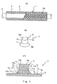
- Figure 1(a) shows an entire, partially sectioned, cleaning sponge roller in accordance with the first embodiment of the present invention
- Figure 1(b) shows an enlarged perspective view of a projection of the sponge roller
- Figure 1(c) shows a cross-sectional view of Figure 1(b).
- the cleaning sponge roller 1 is composed of a porous polyvinyl acetal material (porous PVAt material), which is elastic in a wet state.
- the porous PVAt material is hard in a dry state and soft in a wet state. Additionally, it has excellent water absorption and water-holding properties, shows desirable flexibility and moderate repulsive elasticity in a wet state, and has high abrasion resistance.
- a sponge roller 1 comprises a generally cylindrical-shaped roller body 3 and a plurality of projections 5 formed integrally on the outer peripheral surface 3a of the roller body 3.
- the projection 5 comprises a projection base portion 11 protruding integrally from the outer peripheral surface 3a of the roller body 3 and a projection end portion 13 extending integrally from the top surface 11b of the projection base portion 11.
- the base end surface 11a of the projection base portion 11 is contained in the outer peripheral surface 3a of the roller body 3.
- the top surface 11b of the projection base portion 11 and the base end surface 13a of the projection end portion 13 are substantially in agreement with each other.
- the projection base portion 11 comprises a sloping side (an outer surface) 15 formed in a linearly divergent shape directed toward the outer peripheral surface 3a of the roller body 3.
- the projection base portion 11 is configured to be generally a truncated cone converging toward the top surface 11b from the base end surface 11a.
- the height h from the base end surface 11a of the projection base portion 11 to the top surface 11b is selected in a range of a fifth to half the height H of the projection 5 (the height from the base end surface 11a of the projection base portion 11 to the top surface 13b of the projection end portion 13).
- a line 17 joining the base edge 15a and top edge 15b of the sloping side 15 is substantially in agreement with the sloping side 15 in any cross-sectional plane, and the crossing angle ⁇ 1 between the line 17 and the outer peripheral surface 3a of the roller body 3 is selected in a range of 30 to 60 degrees.
- the projection end portion 13 extends generally perpendicular to the outer peripheral surface 3a of the roller body 3 and is configured in a generally cylindrical shape having substantially the same cross section from the base end surface 13a to the top surface 13b.
- the top surface 13b of the projection end portion 13 intersects generally perpendicularly the outer peripheral surface of the projection end portion 13.
- the cleaning sponge roller 3 is prepared in such a manner that one or more polyvinyl alcohols (raw material) having an average polymerization degree of 300 ⁇ 2000 and a saponification degree of at least 80% are mixed with water to prepare an aqueous solution, to which are added aldehyde as a cross-linking agent, mineral acid as a catalyst, and starch as a pore-forming material, and the mixture is poured into a mold 21 as shown in Figure 2 and reacted at a temperature of 50 ⁇ 80 °C. After it is removed from the mold, it is rinsed with water so as to remove the pore-forming material, etc.
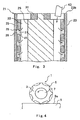
- the mold 21 comprises an outer mold 23, an inner mold 25, a bottom plate 27, a center rod 29, and a cap 31.
- the outer mold 23 and inner mold 25 both are formed in a cylindrical shape.
- the inner mold 25 has an outer diameter equal to or slightly less than an inner diameter of the outer mold 23 and is inserted into the outer mold 23.
- the center rod 29 is inserted generally in the center of the inner mold 25.
- the bottom plate 27 closes bottom edges 23a and 25a of the outer mold 23 and inner mold 25, and also supports the end 29a of the center rod 29.
- the cap 31 is fitted into the inner peripheral surface of the upper end 23b of the outer mold 23.
- the center rod 29 is positioned by the bottom plate 27 and the cap 31.
- a first generally cylindrical cavity 33 for forming the roller body 3 is defined between the inner peripheral surface of the inner mold 25 and the outer peripheral surface of the center rod 33.
- the inner mold 25 has a plurality of through holes (second cavities) 35 for shaping projections 5.
- the through holes 35 each comprise a base-forming cavity 37 for forming the projection base portion 11 in communication with the first cavity 33 and an end-forming cavity 39 for forming the projection end portion 13 in communication with the base-forming cavity 37.
- the base-forming cavity 37 has a sloping side 41 diverging toward the first cavity 33 from the end-forming cavity 39.
- the liquid mixture is injected into the first cavity 33 through a casting nozzle 43 which is inserted between the outer mold 23 and the cap 31 and flows from the first cavity into each through holes 35. Then, the liquid mixture is guided by the sloping side 41 diverging toward the first cavity 33 to flow smoothly into the end-forming cavity 39. At the same time, air in the through holes 35 moves smoothly into the first cavity 33 from the end forming cavities 39 and is discharged out of the upper end of the first cavity 33 into the atmosphere, thereby ensuring that the liquid mixture is filled into the extreme end of the through holes 35 (the end-forming cavities 39). A yield is accordingly improved and manufacturing costs can reduce.
- a porous PVAt material has a 30 % compressive stress of not less than 15 g/cm 2 and not more than 150 g/cm 2 in a proper hydrous condition.
- the proper hydrous condition means a hydrous condition in which the porous PVAt material could exhibit suitable elasticity, which can be obtained in the range of 100 % to 1000% of a water content (weight percent of water based on a dry weight).
- the 30 % compressive stress is obtained in such a manner that a porous PVAt material in a proper hydrous condition is cut to a length of 30 mm between the opposing ends (longitudinal height), which is then placed in a digital load meter with a load exerted on the entire end surfaces; when the length of the material is pressed down by 30% (9mm) in the longitudinal direction, the load is recorded and divided by the area of the end surface to give the 30 % compressive stress.
- the reason why the preferable upper limit of the 30 % compressive stress in a proper hydrous condition is set to 150 g/cm 2 is that if the value is more than 150 g/cm 2 , a porous PVAt material is too hard to exhibit the elasticity required for brushing.
- the reason why the preferable lower limit of the 30 % compressive stress in a proper hydrous condition is set to 15 g/cm 2 is that a porous PVAt material having less than 15 g/cm 2 is too soft, so that deformation takes place when the roller body 3 is rotated.
- the porosity of a porous PVAt material is preferably not less than 85% and not more than 95% with an average pore diameter of 10 ⁇ m to 200 ⁇ m.
- the porosity is less than 85 %, the flexibility in a wet state is insufficient, and if the porosity is more than 95 %, the practical strength is poor. The both cases are not suitable for use in cleaning. Moreover, if an average pore diameter is less than 10 ⁇ m, the elasticity in a wet state is not enough to get a sufficient cleaning effect, and if it is beyond 200 ⁇ m, mesh is too coarse for minute cleaning.
- the average pore diameter is a value measured in accordance with ASTM (Designation: D4404-84), more specifically, determined by pressurized mercury porosimetry using a mercury porosimeter manufactured by PORUS MATERIALS, INC.
- Cleaning of an object 9 to be cleaned is carried out by having the tops 5a of the projections 5 contact with the surface 9a of an object 9 to be cleaned while the projections are being rotationally moved by rotation of the rotational shaft 7.
- the top 5a of the projection 5 comprises a top portion including the top surface 13b of the projection end portion 13.
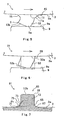
- the top 5a of the projection 5 frequently switches the state between the deformation state where it is laterally pressed by an object 9 to be cleaned (see Figure 5) and the deformation-released state where it is disengaged from the object 9 to be cleaned, thereby brushing the surface 9a to be cleaned.
- the object 9 to be cleaned is satisfactorily cleaned by the brushing function of the projection 5.
- the tensions exerted on projection 5 in contact with the surface 9a to be cleaned is localized on the base end of the projection 5 (the base end surface 11a of the projection base portion 11) similarly as illustrated in Figure 6.
- the projection base portion 11 has the outer surface 15 shaped diverging toward the outer peripheral surface 3a of the roller body 3 and the projection base portion 11 has a cross-section reducing gradually toward the projection end portion 13 from the maximum at the base end surface 11a, and thus, when the projection 5 is pressed laterally, the stress concentration in the vicinity of the base end surface 11a where tension is localized is relaxed. Accordingly, deformation is distributed throughout the projection base portion 11, and it is ensured to prevent breaking of the front end 45 in a moving direction of the base end surface 11a, thereby improving the durability of the projection 5.
- the projection end portion 13 in contact with an object 9 to be cleaned can be configured in any suitable shape without restriction.
- the stress concentration in the vicinity of the base end surface 11a of the projection base portion 11 is relaxed so that deformation is distributed throughout the projection base portion 11and the durability of the projection 5 is improved.
- the projection end portion 13 in contact with an object 9 to be cleaned can be designed in any shape suitable for brushing without restriction and the durability of projection 5 can be improved without compromising a cleaning performance.
- the mold 21 into which a liquid mixture is injected in manufacturing the sponge roller 1 has a first cavity 33 for forming the roller body 3 and through-holes 35 for forming projections 5 comprising base-forming cavities 37 for forming projection base portions 11 and end-forming cavities 39 for forming the projection end portions 13, and the base-forming cavities 37 each have a sloping side 41 diverging toward the first cavity 33.
- the liquid mixture injected into the first cavity 33 is guided by the sloping side 41 to move smoothly into the end-forming cavities 39, and air in the through-holes 35 moves smoothly into the first cavity 33 from the end-forming cavities 39 and is discharged into the atmosphere.
- the liquid mixture reliably fill the closed distal ends of the through-holes 35, thereby reducing the production costs on account of the improved yield.
- Both the subject sample and the comparison sample are composed of a porous PVAt material having a porosity of 90%, an average pore diameter of 130 ⁇ m, and a 30 % compressive stress in a proper hydrous condition of 60g/ cm 2 .
- the projection 5 of the subject sample has an entire height of 4.5mm, an outer diameter of the projection end portion 13 of 7.5mm, a height h of the projection base portion 11 of 1.5mm, and a crossing angle ⁇ of the sloping side 11 with respect to the outer peripheral surface 3a of about 45 degrees (an outer diameter of the base end surface 11a of the projection base portion 11 of 10.5mm).
- the projection 53 of the comparison sample has an entire height of 4.5mm and an outer diameter of 7.5mm.
- the tension strength is measured by clamping the projections 5, 53 with clips (not shown) with the roller body 3 of each of the samples being held by a chuck (not shown) and pulling the clips until a critical point at which fracture occurrs in the projections 5, 53.
- the test results prove that the comparison sample had the tensile strength of 1.59kg whereas the subject sample had the tensile strength of 1.85kg, and thus the tensile strength of the subject sample was increased by 16.4% over the comparison sample.
- Figure 7 is an enlarged sectional view of a main portion showing a projection 63 of a PVAt cleaning sponge roller 61 of the present embodiment. Same numerals are indicated for components similar to those in the first embodiment and detailed description is omitted here.
- the projection 63 according to this embodiment is different from that of the first embodiment in that the projection base portion 65 has a curved outer surface 67 and a curved portion 59 is formed at the boundary between the outer peripheral surface of the projection end portion 13 and the top surface 13b.
- a cross angle ⁇ 2 between a line 75 joining the base end 71 of the outer surface 67 of the projection base portion 65 and the top portion 73 and the outer peripheral surface 3a of the roller body 3 is selected to not less than 30 degrees and not more than 60 degrees.
- the durability of the projection 63 is improved without a compromise with cleaning performance, and the manufacturing costs can be reduced on account of improvement of the yield.
- the projection base portions 11, 65 and the projection end portion 13 were described above with a generally cylindrical shape in cross-section in the first and second embodiments, the present invention should not be limited to that shape, and the cross-section can be of any shape, such as rectangular, ellipse, and oval.
- the stress concentration in the vicinity of the base end of the projection base portion is relaxed, so that deformation is distributed throughout the projection base portion and the durability of the projection is improved.
- the durability of the projection can be improved without changing the shape of the projection end portion
- the projection end portion in contact with an object to be cleaned can be configured without restriction in any shape suitable for brushing and the durability of the projection can be improved without a compromise with cleaning performance.
- a mold into which a liquid mixture is injected in manufacturing a sponge roller comprises a first cavity for forming a roller body and second cavities for forming projections including base-forming cavities for forming projection base portions and end-forming cavities for forming projection end portions, the base-forming cavities each having a sloping side diverging toward the first cavity.
- the liquid mixture injected into the first cavity is guided by the sloping side to move smoothly into the end-forming cavities, and air in the cavities moves smoothly into the first cavity from the end-forming cavities and is discharged into the atmosphere.
- the liquid mixture reliably fills the distal ends of the second cavities, thereby reducing the production cost on account of the improvement of the yield.
Landscapes
- Cleaning In General (AREA)
- Cleaning Or Drying Semiconductors (AREA)
- Cleaning Implements For Floors, Carpets, Furniture, Walls, And The Like (AREA)
- Rolls And Other Rotary Bodies (AREA)
Description
- The present invention relates to a cleaning sponge roller capable of scrubbing fine particles off extremely efficiently, such as abrasive grains, cutting dusts, polishing dusts adhered to the surface of an object to be cleaned after a working process such as polishing in a process of manufacturing aluminum disks for magnetic recording, substrates of semiconductor silicon wafers and the like without damaging the surface of an object to be cleaned.
- In a process of producing hard disks, glass disks, silicon wafers, semiconductor devices during a CMP process, photo masks, liquid glass substrates, etc., high accuracy scouring, so called polishing, is carried out with various abrasive grains, such as silicon oxide, alumina or ceria in order to finish the surface thereof extremely accurate.
- It needs to clean them thoroughly prior to the next process, since the surface of a polished object, such as hard disks, silicon wafers after polished, could be contaminated with abrasive grains, or polishing dusts.
- RCA cleaning has been known for a cleaning process for silicon wafers where a mixture of aqueous ammonia and hydrogen peroxide, diluted fluoric acid, a mixture of hydrochloric acid and hydrogen peroxide are used in this order. Additionally, a cleaning sponge roller having, on its outer surface, a plurality of projections of a porous material of a polyvinyl acetal (hereinafter abbreviated as PVAt) has been known for cleaning hard disks, silicon wafers and the like after polishing them. More specifically, the tops of the projections of the sponge roller are rotated in contact with the surface to be cleaned of an object, whereby the surface to be cleaned is scrubbed by the projections and the object to be cleaned is cleaned sufficiently.
- In cleaning, the projections of the sponge roller brush the surface to be cleaned, while switching very frequently between a deformation state where they are laterally deformed by the object to be cleaned and a deformation-released state where they are disengaged from the object to be cleaned. Then the tension acting on the projections is localized on the base end of the projections, so that the portion adjacent to the base end of the projections is deformed considerably. Therefore, the portion adjacent to the base end of the projections has a tendency to break. When many of the projections are broken, the sponge roller should be exchanged, since the entire sponge roller is constructed integrally.
- It is possible to overcome such a problem by forming the entire shape of the projection larger so as to increase the strength. However, if the entire projection is formed larger, the desired brushing effect could not be achieved and the cleaning efficiency would most provably be reduced. U.S. Patent No. 4566911 of Kanebo Ltd. entitled "Method for cleaning article by scrubbing with cleaning roll" describes a method for cleaning an article by removing cuttings, shavings, turnings, abrasive grains, and the like from the surface of the article, comprising scrubbing the surface of the article by means of a cleaning roll having a surface layer of polyvinyl acetal porous elastic material having a porosity of 85% to 95%, an average pore opening of 10 to 200 µm, and a 30% compression stress in the state characterized by a water content of 100%, based on the dry weight of the material, of 15 to 150 g/cm2. whereby said surface is thoroughly cleaned of even fine particles without causing damage to the fine finish of said surface. In one embodiment, the cleaning roll has columnar projections on the surface thereof, which would experience the breakage described above.
- Thus the object of the present invention is to provide a PVAt cleaning sponge roller having enhanced durability without a compromise with the cleaning performance.
- In an unrelated field of the art, German Patent No. 632 357 of Anna Hempel in Berlin entitled "Rubber Brush for Cleaning Garments" discloses a rubber brush having a plurality of rubber spikes, wherein the diameter of each spike changes along its length. This patent does not relate to the field of cleaning sponge rollers.
- In order to achieve the object mentioned above, the present invention provides a cleaning sponge roller as defined in
claim 1. - The projection base portion may be formed in a generally truncated cone shape and the projection end portion in a generally cylindrical shape.
- In the construction described above, the projection base portion of the projection has an outer surface diverging toward the outer peripheral surface of the roller body and the cross section of the projection base portion is largest at the base end (an interface between the outer peripheral surface of the roller body and the projection base portion) and reduces gradually toward the projection end portion. Thus, when the projection is pressed laterally, the stress concentration in the vicinity of the base end of the projection base portion where tensions is localized is relaxed, and the deformation is distributed throughout the entire projection base portion, so that the durability of the projection can be enhanced.
- Additionally, the projection end portion in contact with an object to be cleaned can be formed in any shape and size best suited for brushing, since the durability of the projection can be enhanced without affecting the shape of the projection end portion.
- Incidentally, a cleaning sponge roller constructed from a polyvinylacetal porous sponge can be prepared by having a viscous liquid mixture containing raw materials react in a mold. A mold corresponding to the shape of the sponge roller described above has a first cavity for forming the roller body and a plurality of second cavities for forming the projections. The second cavities each have a base portion-forming cavity in communication with the first cavity for forming the projection base portion and an end portion-forming cavity in communication with the base portion-forming cavity for forming the projection end portion. The base portion-forming cavity has a sloping side diverging toward the first cavity from the end portion-forming cavity. When the sponge roller is fabricated, the liquid mixture is injected into the first cavity and then flows from the first cavity into each of the second cavities. Since the base portion-forming cavity of the second cavity has the sloping side diverging toward the first cavity, the liquid mixture is guided by the sloping side of the base portion-forming cavity so as to flow smoothly into the end portion-forming cavity. Simultaneously, air in the second cavity moves smoothly into the first cavity from the end portion forming cavity and is discharged from the first cavity to the atmosphere, to thereby ensure that the liquid mixture is filled into the extreme end of the second cavity so that the manufacturing costs can be reduced on account of improvement of a yield.
- The height of the top of the projection base portion from the outer peripheral surface of the roller body is equal to or less than half the height of the projection, and equal to or more than a fifth of the height of the projection.
- If the projection base portion is higher than half the height of the entire projection, deformation of the projection end portion may be kept small and therefore the brushing efficiency in cleaning may be possibly insufficient. Meanwhile, if it is less than a fifth of the height, sufficient strength may not be obtained.
- Furthermore, a crossing angle between a line joining the top and base ends of the outer surface of the projection base portion in any cross section and the outer peripheral surface of the roller body is not less than 30 degrees and not more than 60 degrees.
- If the crossing angle is less than 30 degrees, the projection base portion becomes much larger toward the outer peripheral surface, and the area of the bottom surface of the projection base portion increases so that the total number of the projections to be formed on the outer peripheral surface of the roller body might be restricted. Meanwhile, if the crossing angle is over 60 degrees, sufficient strength may not be attained.
- Incidentally, the shape of the outer surface of the projection base portion may be a linear sloping side or curved sloping side.
-
- Figure 1(a) shows a partially cross-sectional view of the cleaning sponge roller in accordance with the present invention, Figure 1(b) shows an enlarged perspective view of a projection of the sponge roller, and Figure 1(c) shows a cross-sectional view of a projection of the sponge roller of Figure 1(b).
- Figure 2 is a perspective view, partially cutaway, of a mold for molding the sponge roller of Figure 1.
- Figure 3 is a cross-sectional view showing a process of fabricating the sponge roller of Figure 1.
- Figure 4 is a side view schematically showing use of the sponge roller of Figure 1.
- Figure 5 is an enlarged view of a main portion of Figure 4.
- Figure 6 is an enlarged view of a main portion of use of a projection for comparison.
- Figure 7 is a cross-sectional view of a projection of the sponge roller of the second embodiment in accordance with the present invention.
- Figure 8 is a graph showing the results of comparison tests.
- With reference to the drawings, the first embodiment of the present invention will be described hereinafter.
- Figure 1(a) shows an entire, partially sectioned, cleaning sponge roller in accordance with the first embodiment of the present invention, Figure 1(b) shows an enlarged perspective view of a projection of the sponge roller, and Figure 1(c) shows a cross-sectional view of Figure 1(b).
- The cleaning
sponge roller 1 is composed of a porous polyvinyl acetal material (porous PVAt material), which is elastic in a wet state. The porous PVAt material is hard in a dry state and soft in a wet state. Additionally, it has excellent water absorption and water-holding properties, shows desirable flexibility and moderate repulsive elasticity in a wet state, and has high abrasion resistance. - As shown in Figure 1(a), a
sponge roller 1 comprises a generally cylindrical-shaped roller body 3 and a plurality ofprojections 5 formed integrally on the outerperipheral surface 3a of theroller body 3. - As shown in Figures 1(b) and (c), the
projection 5 comprises aprojection base portion 11 protruding integrally from the outerperipheral surface 3a of theroller body 3 and aprojection end portion 13 extending integrally from thetop surface 11b of theprojection base portion 11. Thebase end surface 11a of theprojection base portion 11 is contained in the outerperipheral surface 3a of theroller body 3. Thetop surface 11b of theprojection base portion 11 and thebase end surface 13a of theprojection end portion 13 are substantially in agreement with each other. Theprojection base portion 11 comprises a sloping side (an outer surface) 15 formed in a linearly divergent shape directed toward the outerperipheral surface 3a of theroller body 3. - The
projection base portion 11 is configured to be generally a truncated cone converging toward thetop surface 11b from thebase end surface 11a. The height h from thebase end surface 11a of theprojection base portion 11 to thetop surface 11b is selected in a range of a fifth to half the height H of the projection 5 (the height from thebase end surface 11a of theprojection base portion 11 to thetop surface 13b of the projection end portion 13). As shown in Figure 1 (c), a line 17 joining thebase edge 15a andtop edge 15b of the slopingside 15 is substantially in agreement with the slopingside 15 in any cross-sectional plane, and the crossing angle θ1 between the line 17 and the outerperipheral surface 3a of theroller body 3 is selected in a range of 30 to 60 degrees. - The
projection end portion 13 extends generally perpendicular to the outerperipheral surface 3a of theroller body 3 and is configured in a generally cylindrical shape having substantially the same cross section from thebase end surface 13a to thetop surface 13b. Thetop surface 13b of theprojection end portion 13 intersects generally perpendicularly the outer peripheral surface of theprojection end portion 13. - The
cleaning sponge roller 3 is prepared in such a manner that one or more polyvinyl alcohols (raw material) having an average polymerization degree of 300 ~ 2000 and a saponification degree of at least 80% are mixed with water to prepare an aqueous solution, to which are added aldehyde as a cross-linking agent, mineral acid as a catalyst, and starch as a pore-forming material, and the mixture is poured into amold 21 as shown in Figure 2 and reacted at a temperature of 50 ~ 80 °C. After it is removed from the mold, it is rinsed with water so as to remove the pore-forming material, etc. - The
mold 21 comprises anouter mold 23, aninner mold 25, abottom plate 27, acenter rod 29, and acap 31. Theouter mold 23 andinner mold 25 both are formed in a cylindrical shape. Theinner mold 25 has an outer diameter equal to or slightly less than an inner diameter of theouter mold 23 and is inserted into theouter mold 23. Thecenter rod 29 is inserted generally in the center of theinner mold 25. Thebottom plate 27 closesbottom edges outer mold 23 andinner mold 25, and also supports theend 29a of thecenter rod 29. Thecap 31 is fitted into the inner peripheral surface of theupper end 23b of theouter mold 23. Thecenter rod 29 is positioned by thebottom plate 27 and thecap 31. - As shown in Figure 3, a first generally
cylindrical cavity 33 for forming theroller body 3 is defined between the inner peripheral surface of theinner mold 25 and the outer peripheral surface of thecenter rod 33. - The
inner mold 25 has a plurality of through holes (second cavities) 35 for shapingprojections 5. The through holes 35 each comprise a base-formingcavity 37 for forming theprojection base portion 11 in communication with thefirst cavity 33 and an end-formingcavity 39 for forming theprojection end portion 13 in communication with the base-formingcavity 37. The base-formingcavity 37 has asloping side 41 diverging toward thefirst cavity 33 from the end-formingcavity 39. - The liquid mixture is injected into the
first cavity 33 through a castingnozzle 43 which is inserted between theouter mold 23 and thecap 31 and flows from the first cavity into each through holes 35. Then, the liquid mixture is guided by the slopingside 41 diverging toward thefirst cavity 33 to flow smoothly into the end-formingcavity 39. At the same time, air in the throughholes 35 moves smoothly into thefirst cavity 33 from theend forming cavities 39 and is discharged out of the upper end of thefirst cavity 33 into the atmosphere, thereby ensuring that the liquid mixture is filled into the extreme end of the through holes 35 (the end-forming cavities 39). A yield is accordingly improved and manufacturing costs can reduce. - Incidentally, it is preferred that a porous PVAt material has a 30 % compressive stress of not less than 15 g/cm2 and not more than 150 g/cm2 in a proper hydrous condition. The proper hydrous condition means a hydrous condition in which the porous PVAt material could exhibit suitable elasticity, which can be obtained in the range of 100 % to 1000% of a water content (weight percent of water based on a dry weight). The 30 % compressive stress is obtained in such a manner that a porous PVAt material in a proper hydrous condition is cut to a length of 30 mm between the opposing ends (longitudinal height), which is then placed in a digital load meter with a load exerted on the entire end surfaces; when the length of the material is pressed down by 30% (9mm) in the longitudinal direction, the load is recorded and divided by the area of the end surface to give the 30 % compressive stress.
- The reason why the preferable upper limit of the 30 % compressive stress in a proper hydrous condition is set to 150 g/cm2 is that if the value is more than 150 g/cm2, a porous PVAt material is too hard to exhibit the elasticity required for brushing. On the other hand, the reason why the preferable lower limit of the 30 % compressive stress in a proper hydrous condition is set to 15 g/cm2 is that a porous PVAt material having less than 15 g/cm2 is too soft, so that deformation takes place when the
roller body 3 is rotated. - The porosity of a porous PVAt material is preferably not less than 85% and not more than 95% with an average pore diameter of 10µm to 200µm.
- If the porosity is less than 85 %, the flexibility in a wet state is insufficient, and if the porosity is more than 95 %, the practical strength is poor. The both cases are not suitable for use in cleaning. Moreover, if an average pore diameter is less than 10 µm, the elasticity in a wet state is not enough to get a sufficient cleaning effect, and if it is beyond 200 µm, mesh is too coarse for minute cleaning.
- Here, the porosity is a value calculated by the following equation (1) with an apparent volume and an absolute volume of a rectangular body of a porous PVAt material which has been fully dried in a dryer, determined with a dry-type automatic densimeter:

- The average pore diameter is a value measured in accordance with ASTM (Designation: D4404-84), more specifically, determined by pressurized mercury porosimetry using a mercury porosimeter manufactured by PORUS MATERIALS, INC.
- Now, a cleaning process using the
sponge roller 1 will be explained. - As illustrated in Figure 4, in the hollow of the
sponge roller 1, inserted is arotational shaft 7 on which theroller body 3 is secured. Cleaning of anobject 9 to be cleaned is carried out by having the tops 5a of theprojections 5 contact with thesurface 9a of anobject 9 to be cleaned while the projections are being rotationally moved by rotation of therotational shaft 7. The top 5a of theprojection 5 comprises a top portion including thetop surface 13b of theprojection end portion 13. The top 5a of theprojection 5 frequently switches the state between the deformation state where it is laterally pressed by anobject 9 to be cleaned (see Figure 5) and the deformation-released state where it is disengaged from theobject 9 to be cleaned, thereby brushing thesurface 9a to be cleaned. Theobject 9 to be cleaned is satisfactorily cleaned by the brushing function of theprojection 5. - Incidentally, as illustrated in Figure 6, in the case of a
sponge roller 51 having generally cylindrical shapedprojections 53 each in substantially the same cross section from abase end surface 53a on the outerperipheral surface 3a of aroller body 3 to atop surface 53 b, tensions exerted on theprojection 53 in contact with asurface 9a to be cleaned is localized on thebase end surface 53a so that it is deformed considerably in the vicinity of thebase end surface 53a. In addition, theouter periphery surface 3a is not a perfect plane and is inclined in an arcuate shape toward the direction opposite the projection direction of theprojection 53, and thus it is easily deformed as compared to that in which it projects from a perfect plane. Therefore thefront portion 55 in a moving direction of thebase end surface 53a has a tendency to break. - On the other hand, even in the case of the
sponge roller 1 in accordance with the present embodiment, the tensions exerted onprojection 5 in contact with thesurface 9a to be cleaned is localized on the base end of the projection 5 (thebase end surface 11a of the projection base portion 11) similarly as illustrated in Figure 6. However as illustrated in Figure 5, theprojection base portion 11 has theouter surface 15 shaped diverging toward the outerperipheral surface 3a of theroller body 3 and theprojection base portion 11 has a cross-section reducing gradually toward theprojection end portion 13 from the maximum at thebase end surface 11a, and thus, when theprojection 5 is pressed laterally, the stress concentration in the vicinity of thebase end surface 11a where tension is localized is relaxed. Accordingly, deformation is distributed throughout theprojection base portion 11, and it is ensured to prevent breaking of thefront end 45 in a moving direction of thebase end surface 11a, thereby improving the durability of theprojection 5. - Furthermore, since the durability of the
projection 5 can be improved without affecting the shape of theprojection end portion 13, theprojection end portion 13 in contact with anobject 9 to be cleaned can be configured in any suitable shape without restriction. - As described above, in accordance with the present embodiment, when the top 5a of the
projection 5 is in contact with anobject 9 to be cleaned and is pressed laterally, the stress concentration in the vicinity of thebase end surface 11a of theprojection base portion 11 is relaxed so that deformation is distributed throughout the projection base portion 11and the durability of theprojection 5 is improved. - In addition, since the durability of the
projection 5 can be improved without affecting the shape of theprojection end portion 13, theprojection end portion 13 in contact with anobject 9 to be cleaned can be designed in any shape suitable for brushing without restriction and the durability ofprojection 5 can be improved without compromising a cleaning performance. - Besides, the
mold 21 into which a liquid mixture is injected in manufacturing thesponge roller 1 has afirst cavity 33 for forming theroller body 3 and through-holes 35 for formingprojections 5 comprising base-formingcavities 37 for formingprojection base portions 11 and end-formingcavities 39 for forming theprojection end portions 13, and the base-formingcavities 37 each have asloping side 41 diverging toward thefirst cavity 33. The liquid mixture injected into thefirst cavity 33 is guided by the slopingside 41 to move smoothly into the end-formingcavities 39, and air in the through-holes 35 moves smoothly into thefirst cavity 33 from the end-formingcavities 39 and is discharged into the atmosphere. Thus, the liquid mixture reliably fill the closed distal ends of the through-holes 35, thereby reducing the production costs on account of the improved yield. - The following is an explanation on the tensile strength tests which were carried out on the
projection 5 of the sponge roller 1 (subject sample of the invention) as shown in Figure 1(b) and on theprojection 53 of the sponge roller 51 (sample for comparison) as shown in Figure 6. - Both the subject sample and the comparison sample are composed of a porous PVAt material having a porosity of 90%, an average pore diameter of 130µm, and a 30 % compressive stress in a proper hydrous condition of 60g/ cm2.
- The
projection 5 of the subject sample has an entire height of 4.5mm, an outer diameter of theprojection end portion 13 of 7.5mm, a height h of theprojection base portion 11 of 1.5mm, and a crossing angle θ of the slopingside 11 with respect to the outerperipheral surface 3a of about 45 degrees (an outer diameter of thebase end surface 11a of theprojection base portion 11 of 10.5mm). Theprojection 53 of the comparison sample has an entire height of 4.5mm and an outer diameter of 7.5mm. - In the tests, the tension strength is measured by clamping the
projections roller body 3 of each of the samples being held by a chuck (not shown) and pulling the clips until a critical point at which fracture occurrs in theprojections - As shown in Figure 8, the test results prove that the comparison sample had the tensile strength of 1.59kg whereas the subject sample had the tensile strength of 1.85kg, and thus the tensile strength of the subject sample was increased by 16.4% over the comparison sample.
- Now the second embodiment of the present invention will be described.
- Figure 7 is an enlarged sectional view of a main portion showing a
projection 63 of a PVAtcleaning sponge roller 61 of the present embodiment. Same numerals are indicated for components similar to those in the first embodiment and detailed description is omitted here. - The
projection 63 according to this embodiment is different from that of the first embodiment in that theprojection base portion 65 has a curvedouter surface 67 and acurved portion 59 is formed at the boundary between the outer peripheral surface of theprojection end portion 13 and thetop surface 13b. - In the cross-section shown in Fig. 7, a cross angle θ2 between a
line 75 joining the base end 71 of theouter surface 67 of theprojection base portion 65 and thetop portion 73 and the outerperipheral surface 3a of theroller body 3 is selected to not less than 30 degrees and not more than 60 degrees. - In accordance with the present embodiment, as in the first embodiment, the durability of the
projection 63 is improved without a compromise with cleaning performance, and the manufacturing costs can be reduced on account of improvement of the yield. - Although the
projection base portions projection end portion 13 were described above with a generally cylindrical shape in cross-section in the first and second embodiments, the present invention should not be limited to that shape, and the cross-section can be of any shape, such as rectangular, ellipse, and oval. - As described above, in accordance with the present invention, when the top of a projection is in contact with an object to be cleaned and the projection is pressed laterally, the stress concentration in the vicinity of the base end of the projection base portion is relaxed, so that deformation is distributed throughout the projection base portion and the durability of the projection is improved.
- In addition, since the durability of the projection can be improved without changing the shape of the projection end portion, the projection end portion in contact with an object to be cleaned can be configured without restriction in any shape suitable for brushing and the durability of the projection can be improved without a compromise with cleaning performance.
- Besides, a mold into which a liquid mixture is injected in manufacturing a sponge roller comprises a first cavity for forming a roller body and second cavities for forming projections including base-forming cavities for forming projection base portions and end-forming cavities for forming projection end portions, the base-forming cavities each having a sloping side diverging toward the first cavity. The liquid mixture injected into the first cavity is guided by the sloping side to move smoothly into the end-forming cavities, and air in the cavities moves smoothly into the first cavity from the end-forming cavities and is discharged into the atmosphere. Thus, the liquid mixture reliably fills the distal ends of the second cavities, thereby reducing the production cost on account of the improvement of the yield.
Claims (2)
- A cleaning sponge roller (1, 61) for removing fine particles from a polished surface, the surface having undergone high accuracy scouring, the cleaning sponge roller (1, 61) composed of a porous polyvinylacetal material which is elastic in a wet state, comprising:a generally cylindrical roller body (3), anda plurality of projections (5, 63) formed integrally on an outer peripheral surface (3a) of said roller body (3) for cleaning an object to be cleaned by having tops (5a) of the projections (5) rotate in contact with a surface of the object,characterised in that
each of said projections (5) comprises a tapering projection base portion (11, 65) extending from the outer peripheral surface (3a) of the roller body and a projection end portion (13) having substantially the same cross sectional shape from a top end (11b) of the projection base portion (11, 65) to the top (5a) of the projection (5), and
a height h from the outer peripheral surface (3a) of the roller body (3) to the top end (11b) of the projection base portion (11, 65) is not less than a fifth and not more than a half of a height H of the projection (5), and a crossing angle between a line joining the top end and the base end of the outer surface (15) of the projection base portion and the outer peripheral surface (3a) of the roller body (3) in any cross-sectional plane is not less than 30 degrees and not more than 60 degrees. - A cleaning sponge roller according to claim 1, characterised in that said projection base portion (11, 65) has a generally truncated cone shape and said projection end portion (13) has a generally cylindrical shape.
Applications Claiming Priority (3)
| Application Number | Priority Date | Filing Date | Title |
|---|---|---|---|
| JP5127499 | 1999-02-26 | ||
| JP05127499A JP3403108B2 (en) | 1999-02-26 | 1999-02-26 | Sponge roller for cleaning |
| PCT/JP2000/000441 WO2000051752A1 (en) | 1999-02-26 | 2000-01-27 | Cleaning sponge roller |
Publications (3)
| Publication Number | Publication Date |
|---|---|
| EP1188492A1 EP1188492A1 (en) | 2002-03-20 |
| EP1188492A4 EP1188492A4 (en) | 2003-02-05 |
| EP1188492B1 true EP1188492B1 (en) | 2006-04-26 |
Family
ID=12882378
Family Applications (1)
| Application Number | Title | Priority Date | Filing Date |
|---|---|---|---|
| EP00901955A Expired - Lifetime EP1188492B1 (en) | 1999-02-26 | 2000-01-27 | Cleaning sponge roller |
Country Status (6)
| Country | Link |
|---|---|
| EP (1) | EP1188492B1 (en) |
| JP (1) | JP3403108B2 (en) |
| KR (1) | KR100571640B1 (en) |
| CN (1) | CN1144626C (en) |
| AU (1) | AU2320200A (en) |
| WO (1) | WO2000051752A1 (en) |
Families Citing this family (20)
| Publication number | Priority date | Publication date | Assignee | Title |
|---|---|---|---|---|
| CA2384357C (en) | 2000-07-10 | 2004-08-10 | Yoshinori Tanaka | Cleaning article |
| WO2005065849A1 (en) * | 2003-12-26 | 2005-07-21 | Aion Co., Ltd. | Core for washing sponge roller |
| CN1954929B (en) * | 2005-10-26 | 2011-06-15 | 特伦普夫格吕施股份公司 | Mechanical device for cleaning back plat of workpiece cradle |
| WO2007067348A2 (en) * | 2005-12-06 | 2007-06-14 | Entegris, Inc. | A molded rotatable base for a porous pad |
| KR101579572B1 (en) * | 2008-06-30 | 2015-12-22 | 아이온 가부시키가이샤 | Sponge roller for cleaning |
| CN101639653B (en) * | 2008-08-01 | 2012-01-04 | 深圳市宝安区松岗富士(中国)制品厂 | Manufacturing process for sponge rollers and press-in device thereof |
| JP5538007B2 (en) * | 2009-08-20 | 2014-07-02 | アイオン株式会社 | Cleaning sponge body and cleaning method |
| JP5977175B2 (en) * | 2010-02-22 | 2016-08-24 | インテグリス・インコーポレーテッド | Cleaning brush after CMP |
| KR101118161B1 (en) * | 2011-05-27 | 2012-03-12 | 주식회사 엠원테크 | Pva brush roller for cleansing of lcd glass and thereof manufacturing method |
| US8778087B2 (en) * | 2012-04-03 | 2014-07-15 | Illinois Tool Works Inc. | Conical sponge brush for cleaning semiconductor wafers |
| US20130255721A1 (en) * | 2012-04-03 | 2013-10-03 | Illinois Tool Works Inc. | Concave nodule sponge brush |
| CN103243532B (en) * | 2013-04-26 | 2016-01-20 | 邵卫娟 | A kind of meticulous clearer |
| JP6163081B2 (en) * | 2013-11-05 | 2017-07-12 | アイオン株式会社 | Brush roller |
| US10790167B2 (en) | 2014-02-20 | 2020-09-29 | Entegris, Inc. | Nodule ratios for targeted enhanced cleaning performance |
| JP6366544B2 (en) * | 2014-07-04 | 2018-08-01 | 株式会社荏原製作所 | Cleaning device and roll cleaning member |
| CN107206438A (en) * | 2014-11-24 | 2017-09-26 | 康宁股份有限公司 | Method and apparatus for substrate surface cleaning |
| JP2018141030A (en) * | 2017-02-27 | 2018-09-13 | 株式会社エー・アイ・システムプロダクト | Electronic cigarette cleaning liquid and electronic cigarette cleaning method |
| CN110335837A (en) * | 2019-07-05 | 2019-10-15 | 北京理工大学 | A kind of semiconductor crystal wafer cleaning preparation method of porous hydrophilic material and component |
| CN113385463A (en) * | 2021-05-10 | 2021-09-14 | 华清八度光电集团有限公司 | Belt cleaning device is used in production of flexible brilliant silicon solar cell panel of environment-friendly |
| KR102698859B1 (en) * | 2022-01-27 | 2024-08-27 | 제너셈(주) | Cleaning apparatus and singulation system of package having the same |
Family Cites Families (9)
| Publication number | Priority date | Publication date | Assignee | Title |
|---|---|---|---|---|
| DE632357C (en) * | 1937-02-01 | Anna Hempel | Rubber brush for cleaning clothes, etc. | |
| JPS596974A (en) * | 1982-07-05 | 1984-01-14 | カネボウ株式会社 | Washing method |
| JPS60186085U (en) * | 1984-05-22 | 1985-12-10 | カネボウ株式会社 | Cleaning roll |
| JPH03257456A (en) * | 1990-03-08 | 1991-11-15 | Fuji Electric Co Ltd | Method for washing cylindrical substrate of electrophotographic sensitive body |
| US6004402A (en) * | 1994-10-06 | 1999-12-21 | Xomed Surgical Products, Inc. | Method of cleaning silicon material with a sponge |
| WO1997013590A1 (en) * | 1995-10-13 | 1997-04-17 | Ontrak Systems, Inc. | Method and apparatus for chemical delivery through the brush |
| US5675856A (en) * | 1996-06-14 | 1997-10-14 | Solid State Equipment Corp. | Wafer scrubbing device |
| JP3680185B2 (en) * | 1996-07-19 | 2005-08-10 | アイオン株式会社 | Cleaning roller |
| JPH10180198A (en) * | 1996-10-21 | 1998-07-07 | Ebara Corp | Cleaning device |
-
1999
- 1999-02-26 JP JP05127499A patent/JP3403108B2/en not_active Expired - Lifetime
-
2000
- 2000-01-27 AU AU23202/00A patent/AU2320200A/en not_active Abandoned
- 2000-01-27 EP EP00901955A patent/EP1188492B1/en not_active Expired - Lifetime
- 2000-01-27 CN CNB008042799A patent/CN1144626C/en not_active Expired - Lifetime
- 2000-01-27 KR KR1020017009387A patent/KR100571640B1/en not_active Expired - Lifetime
- 2000-01-27 WO PCT/JP2000/000441 patent/WO2000051752A1/en not_active Ceased
Also Published As
| Publication number | Publication date |
|---|---|
| AU2320200A (en) | 2000-09-21 |
| JP2000246187A (en) | 2000-09-12 |
| CN1144626C (en) | 2004-04-07 |
| JP3403108B2 (en) | 2003-05-06 |
| EP1188492A1 (en) | 2002-03-20 |
| KR100571640B1 (en) | 2006-04-17 |
| EP1188492A4 (en) | 2003-02-05 |
| WO2000051752A1 (en) | 2000-09-08 |
| CN1341045A (en) | 2002-03-20 |
| KR20010101706A (en) | 2001-11-14 |
Similar Documents
| Publication | Publication Date | Title |
|---|---|---|
| EP1188492A1 (en) | Cleaning sponge roller | |
| US6502273B1 (en) | Cleaning sponge roller | |
| US10870132B2 (en) | Cleaning sponge and cleaning method | |
| KR101579572B1 (en) | Sponge roller for cleaning | |
| US7955693B2 (en) | Foam composition roller brush with embedded mandrel | |
| US6467120B1 (en) | Wafer cleaning brush profile modification | |
| US6802877B2 (en) | Polyvinyl acetal composition roller brush with abrasive outer surface | |
| TWI905244B (en) | Cleaning sponge rollers | |
| JP2009117765A (en) | Sponge roller for cleaning | |
| EP0937509A1 (en) | Sponge roller for cleaning | |
| CN115431189B (en) | Polishing sponge pad | |
| JPWO1998020987A1 (en) | Cleaning sponge roller | |
| US20040151890A1 (en) | Polyvinyl acetal composition skinless roller brush | |
| WO2002003833A1 (en) | Injection molded disposable core featuring recessed pores for substrate treatment member | |
| KR102664024B1 (en) | Brush for cleaning of wafer | |
| KR100944882B1 (en) | Flap rollers and manufacturing method | |
| KR20020058985A (en) | Structure of pancake type brush used for cleaning wafer |
Legal Events
| Date | Code | Title | Description |
|---|---|---|---|
| PUAI | Public reference made under article 153(3) epc to a published international application that has entered the european phase |
Free format text: ORIGINAL CODE: 0009012 |
|
| 17P | Request for examination filed |
Effective date: 20010726 |
|
| AK | Designated contracting states |
Kind code of ref document: A1 Designated state(s): AT BE CH CY DE DK ES FI FR GB GR IE IT LI LU MC NL PT SE |
|
| A4 | Supplementary search report drawn up and despatched |
Effective date: 20021227 |
|
| 17Q | First examination report despatched |
Effective date: 20040202 |
|
| RBV | Designated contracting states (corrected) |
Designated state(s): IE |
|
| GRAP | Despatch of communication of intention to grant a patent |
Free format text: ORIGINAL CODE: EPIDOSNIGR1 |
|
| GRAS | Grant fee paid |
Free format text: ORIGINAL CODE: EPIDOSNIGR3 |
|
| GRAA | (expected) grant |
Free format text: ORIGINAL CODE: 0009210 |
|
| AK | Designated contracting states |
Kind code of ref document: B1 Designated state(s): IE |
|
| REG | Reference to a national code |
Ref country code: IE Ref legal event code: FG4D |
|
| PLBE | No opposition filed within time limit |
Free format text: ORIGINAL CODE: 0009261 |
|
| STAA | Information on the status of an ep patent application or granted ep patent |
Free format text: STATUS: NO OPPOSITION FILED WITHIN TIME LIMIT |
|
| 26N | No opposition filed |
Effective date: 20070129 |
|
| PGFP | Annual fee paid to national office [announced via postgrant information from national office to epo] |
Ref country code: IE Payment date: 20190111 Year of fee payment: 20 |
|
| REG | Reference to a national code |
Ref country code: IE Ref legal event code: MK9A |
|
| PG25 | Lapsed in a contracting state [announced via postgrant information from national office to epo] |
Ref country code: IE Free format text: LAPSE BECAUSE OF EXPIRATION OF PROTECTION Effective date: 20200127 |