EP1187397B1 - Reconfiguration d'un réseau ad hoc - Google Patents
Reconfiguration d'un réseau ad hoc Download PDFInfo
- Publication number
- EP1187397B1 EP1187397B1 EP01000437A EP01000437A EP1187397B1 EP 1187397 B1 EP1187397 B1 EP 1187397B1 EP 01000437 A EP01000437 A EP 01000437A EP 01000437 A EP01000437 A EP 01000437A EP 1187397 B1 EP1187397 B1 EP 1187397B1
- Authority
- EP
- European Patent Office
- Prior art keywords
- terminal
- network
- terminals
- sub
- controller
- Prior art date
- Legal status (The legal status is an assumption and is not a legal conclusion. Google has not performed a legal analysis and makes no representation as to the accuracy of the status listed.)
- Expired - Lifetime
Links
Images
Classifications
-
- H—ELECTRICITY
- H04—ELECTRIC COMMUNICATION TECHNIQUE
- H04L—TRANSMISSION OF DIGITAL INFORMATION, e.g. TELEGRAPHIC COMMUNICATION
- H04L12/00—Data switching networks
- H04L12/28—Data switching networks characterised by path configuration, e.g. LAN [Local Area Networks] or WAN [Wide Area Networks]
- H04L12/46—Interconnection of networks
-
- H—ELECTRICITY
- H04—ELECTRIC COMMUNICATION TECHNIQUE
- H04W—WIRELESS COMMUNICATION NETWORKS
- H04W84/00—Network topologies
- H04W84/18—Self-organising networks, e.g. ad-hoc networks or sensor networks
- H04W84/20—Master-slave selection or change arrangements
-
- H—ELECTRICITY
- H04—ELECTRIC COMMUNICATION TECHNIQUE
- H04Q—SELECTING
- H04Q11/00—Selecting arrangements for multiplex systems
- H04Q11/04—Selecting arrangements for multiplex systems for time-division multiplexing
- H04Q11/0428—Integrated services digital network, i.e. systems for transmission of different types of digitised signals, e.g. speech, data, telecentral, television signals
- H04Q11/0478—Provisions for broadband connections
-
- H—ELECTRICITY
- H04—ELECTRIC COMMUNICATION TECHNIQUE
- H04L—TRANSMISSION OF DIGITAL INFORMATION, e.g. TELEGRAPHIC COMMUNICATION
- H04L12/00—Data switching networks
- H04L12/54—Store-and-forward switching systems
- H04L12/56—Packet switching systems
- H04L12/5601—Transfer mode dependent, e.g. ATM
- H04L2012/5603—Access techniques
- H04L2012/5604—Medium of transmission, e.g. fibre, cable, radio
- H04L2012/5607—Radio
-
- H—ELECTRICITY
- H04—ELECTRIC COMMUNICATION TECHNIQUE
- H04L—TRANSMISSION OF DIGITAL INFORMATION, e.g. TELEGRAPHIC COMMUNICATION
- H04L12/00—Data switching networks
- H04L12/54—Store-and-forward switching systems
- H04L12/56—Packet switching systems
- H04L12/5601—Transfer mode dependent, e.g. ATM
- H04L2012/5603—Access techniques
- H04L2012/5609—Topology
- H04L2012/5612—Ring
Definitions
- the invention relates to a wireless adhoc network with multiple terminals.
- ad hoc networks are self-organizing and can be made, for example consist of several sub-networks.
- each terminal calculates the sum of the distances to its respective neighboring terminals and divides this sum by the number of neighboring terminals. The terminal with the lowest value becomes the new controller.
- the ICT Highest In-Cluster Traffic
- the terminal that has the highest traffic with the neighboring terminals is selected as the controller.
- a network which has a fixed installed infrastructure with access points. These access points serve as Controller for control.
- Each controller has a technical conditional, predetermined transmission range. Within this area is wireless, registered terminals data exchange with the access points possible. At predetermined time intervals, the terminals send a topological broadcast every accessible network participant. In this case, a matrix is sent, which the respective network address and a list of all network addresses from the Terminal previously received includes.
- the Controller construct the spatial structure of the network and regularly To update. Is there a terminal in the transmission area of two Access Points, the network addresses are compared, with the access point being the shorter Assigned network address, the controller takes over.
- the invention has for its object to provide a network which Measures to easily find a terminal with a control function (Controller).
- the network Traffic conditions stored at predetermined intervals can for example the measurement of the reception field strength or the measurement of the user data traffic of a Terminals to another terminal. It is also possible that at least that as Controller called terminal with the network control function for storage the traffic conditions between at least part of the terminals in the form of a Matrix is provided.
- a change of network control function from one Terminal, i. the change of controller function, may be required if this based on the stored traffic conditions or the matrix is determined. These Decision may be the previous controller or any terminal under the Make a condition that has been distributed to this the stored matrix.
- a criterion for the controller change can be a value that is the sum divided all receive field strengths of a terminal to its neighboring terminals by the number of adjacent terminals. The terminal with the least Value then takes over the controller function. Another criterion can be a value be the sum of the user traffic of a terminal with the adjacent terminals. The terminal with the highest value then becomes Controller.
- the network can also have multiple subnetworks with one each as a controller denote the respective network control function of the subnetwork Terminal included. These sub-networks exchange via bridge terminals Messages and data. At least one terminal in a subnetwork is used for Storage of own traffic conditions and the traffic conditions of others Sub-networks. When changing the traffic conditions, the sub-networks get other controllers and thus possibly other associated terminals.
- the data transmitted in the network may e.g. after one Be generated packet transmission method.
- the packages can be total or as partial packages after adding more information over the wireless medium.
- Under a wireless transmission is a radio, infrared, ultrasonic transmission, etc. to understand.
- As a packet transmission method for example, the asynchronous Transtermode (ATM), which generates fixed-length packets, the cells to be named.
- ATM asynchronous Transtermode
- each terminal is self-organizing
- Such an ad hoc network can provide access to a fixed network and can be used immediately.
- An ad hoc network is characterized in that the Structure and the number of participants within preset limits not is fixed. For example, a communication device of a subscriber may be off taken or integrated into the network.
- Unlike traditional Mobile networks is not an Ajhoc network on a fixed infrastructure reliant.
- the size of the area of the Ajhoc network is usually much larger than that Transmission area of a terminal.
- a communication between two terminals may therefore require the involvement of additional terminals for this Transfer messages or data between the two communicating terminals can.
- Such adhoc networks that involve forwarding messages and Data through a terminal is necessary as multihop ad hoc networks designated.
- One possible organization of an ad hoc network is to be regular Sub-networks or clusters form.
- a sub-network of the adhoc network can for example, via terminals connected by radio links from around a table be formed sitting participants.
- Such terminals may e.g. communication devices for wireless exchange of documents, images, etc.
- ad hoc networks You can specify two types of ad hoc networks. These are decentralized and centralized ad hoc networks.
- a decentralized ad hoc network the communication between the terminals is decentralized, ie each terminal can communicate directly with each other terminal, provided that the terminals are each in the transmission area of the other terminal.
- the advantage of a decentralized ad hoc network is its simplicity and robustness against errors.
- CC central terminal or central controller
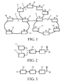
- Fig. 1 is an embodiment of an ad hoc network with three sub-networks. 1 to 3, each containing a plurality of terminals 4 to 16. Part of the subnetwork 1, the terminals 4 to 9, the sub-network 2, the terminals 4 and 10 to 12 and the sub-network 3, the terminals 5 and 13 to 16.
- the respective terminals belonging to a subnetwork exchange data over radio links out.
- the ellipses shown in FIG. 1 indicate the radio range of a subnetwork (1 to 3) in which between the terminals belonging to the subnet a largely problem-free radio transmission is possible.
- Terminals 4 and 5 are called bridge terminals because they exchange data between two sub-networks 1 and 2 or 1 and 3 allow.
- the Bridge Terminal 4 is for traffic between sub-networks 1 and 2 and the bridge terminal 5 for the traffic between the sub-networks 1 and 3 responsible.
- a terminal 4 to 16 of the local area network of FIG. 1 may be mobile or fixed Communication device and contains recordable, at least one station 17, a connection control device 18 and a radio device 19 with antenna 20, as shown in FIG.
- a station 17 may be, for example, a portable computer, Be a telephone, etc.
- a radio device 19 of the terminals 6 to 16 contains, as shown in FIG. 3, except the Antenna 20, a high-frequency circuit 21, a modem 22 and a Protocol device 23.
- the protocol device 23 forms from that of the Connection control device 18 received data stream packet units.
- a Packet unit contains portions of the data stream and additional from the protocol device 23 formed control information.
- LLC Logical Link Control
- MAC Medium Access control
- a subnet 1 to 3 is a centralized adhoc network a specific terminal responsible for the control and management functions and is referred to as a central controller.
- the controller is also working as a normal terminal in the associated sub-network
- the controller is e.g. for the Registration of terminals that operate on the subnetwork for the Establishing a connection between at least two terminals in the radio transmission medium, for resource management and for access control in the radio transmission medium
- a terminal of a subnetwork gets after the Registration and after the registration of a transfer request from the controller Transmission capacity for data (packet units) assigned.
- TDMA Time Division Multiplex Access
- CDMA Frequency Division Multiplex Access
- the procedures can also be combined.
- Each sub-network 1 to 3 of the local area network is assigned a number of designated channels, referred to as channel bundles.
- a channel is determined by a frequency range, a time range and, for example, in the CDMA method by a spreading code.
- each sub-network 1 to 3 for data exchange a certain, each different frequency range with a carrier frequency f i are available. In such a frequency range, for example, data can be transmitted by means of the TDMA method.
- the bridge terminal 4 works on the one hand, in order to be able to carry out a data exchange with the other terminals of the sub-network 1, with the carrier frequency f 1 and on the other hand, in order to be able to exchange data with the other terminals of the sub-network 2, with the Carrier frequency f 2 .
- the second bridge terminal 5 included in the local network, which transmits data between the sub-networks 1 and 3, operates at the carrier frequencies f 1 and f 3 .
- the central controller has, for example, the function of Access control.
- MAC frame MAC layer
- TDMA method applied.
- Such a MAC frame has different channels for control information and user data.
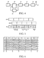
- FIG. 4 A block diagram of an embodiment of a bridge terminal is shown in FIG. 4 shown.
- the radio switching device of this bridge terminal contains one each Protocol device 24, a modem 25 and a radio frequency circuit 26 with antenna 27.
- the protocol device 24 is connected to a radio switching device 28, which is the another to a connection control device 29 and a buffer device 30 is connected.
- the latching device 30 includes therein Embodiment, a memory element and is used for caching data and is implemented as a FIFO building block (First In First Out), i. the data will be in the Order read from the buffer device 30 in which they are written
- the terminal shown in Fig. 4 can also be used as a normal terminal work. Connected to the connection control device 29 stations that are not in 4, then deliver data via the connection control device 29 to the radio switching device 28.
- the bridge terminal of FIG. 4 is alternating with first and second sub-networks synchronized. Under synchronization is the whole process of involvement of a terminal in the sub-network until the exchange of data. If that Bridge terminal is synchronized with the first sub-network, it can data with all terminals and with the controller of this first subnetwork from the connection control device 29 data to the radio switching device 28th whose destination is a terminal or the controller of the first sub-network or a terminal or controller of another subnetwork is over reach the first sub-network, the radio switching device forwards this data directly to the protocol device 24 on. In the protocol device 24, the Cached data until the time specified by the controller for the transmission is achieved.
- the radio transmission must be delayed until the time period in which the bridge terminal is synchronized with the second subnetwork. Therefore, the radio switching device forwards the data whose destination is in the second subnetwork or whose destination can be reached via the second sub-network, to the buffer device 30, which latches the data until the bridge terminal is synchronized with the second subnetwork.
- the MAC frames of two subnetworks SN1 and SN2 are usually not synchronized. Therefore, a bridge terminal BT with a sub-network SN1 or SN2 not only during a switching time Ts but also during a waiting time Tw not connected.
- Fig. 5 shows a sequence of MAC frames sub-networks SN1 and SN2 and the MAC frame structure of the bridge terminal BT shows.
- the switching time Ts is the time required for the Bridge terminal can synchronize with a subnetwork.
- the waiting time Tw gives the time between the end of synchronization with the subnetwork and the Start of a new MAC frame of this subnetwork.
- the bridge terminal BT points BT only a channel capacity of 1/4 of the available channel capacity of a sub-network on.
- the channel capacity is half the available channel capacity of a subnetwork.
- each subnet contains a central controller for Control of the assigned subnetwork.
- commissioning a sub-network It must be ensured that only one terminal has the function of the central controller takes over. It is assumed that not every terminal has the function of the central one Controller can take over. It becomes the determination of a central controller For example, proceeding so that each terminal, which has a controller function can take over, checks whether another terminal is in their reception area, which can perform the controller function. If so, the detecting terminal will stop realizes that it will not become controller. All other terminals also carry these Checks through, remains at the end of a terminal, which no other terminal detected with a controller function and thus assumes the controller function.
- a distance matrix (distance matrix), which via the measurement of the reception field strength RSS2 (Recieved signal strength) directly the distance between two terminals in free space indicates.
- RSS2 received signal strength
- FIG. 6 An example of such a distance matrix is shown in FIG. 6.
- RSS2 (x, y) means the wn of the terminal Tx measured field strength of the Terminals Ty.
- Each terminal calculates the sum of all reception field strengths (RSS2 (x, y)) to its direct neighbors and divides this sum by the number of direct neighbors. The terminal with the least charge Value is then the new controller. This method is hereafter referred to as LDV (lowest distance value).
- each terminal in the environment of the previous one central controller can be determined by this previous controller itself.
- the previous controller itself knows all receive field strengths (RSS2) of the terminals in its previous sub-network. These are during operation of the individual terminals his Sub-NetzMerk determined and communicated to the previous controller. Further the previous controller also knows the distance matrices of its neighboring or even more distant sub-networks. These are the previous controller of the Controllers of other sub-networks have been notified regularly. Likewise, the previous controllers its distance matrix the controllers of other subnetworks transfer. As a result, the previous controller not only knows the Receive fdd strengths of its associated terminals (the terminals in its subnet), but also from other sub-networks.
- Previous controllers calculate which terminal has the lowest removal value (LDV). This can also be the previous controller. If the new controller not the previous controller, there still needs to be an exchange of control information occur.
- LDV lowest removal value
- the previous controller uses the distance matrices in distribution mode (broadcast) to the terminals of its Sub-Nebtechnikes sends and this decide independently who will be the central controller.
- each terminal prefferably broadcast periodically in broadcast mode. its own average receive field strengths (RSS2), which are then transmitted by the neighboring terminals are received. Each terminal then decides independently, whether it turns into the central controller.
- RSS2 average receive field strengths
- One terminal continuously collects the average, from one adjacent Terminal sent receive field strengths (RSS2).
- the received receive field strengths are stored in a terminal and the sum of the receive field strengths is shared calculated by number of neighboring terminals. After a long time, one should stored receive field strength and thus the calculated value of a terminal deleted if it has not been received by it for the specified period of time. This is to avoid that terminals are not considered long are no longer active
- the terminal then becomes the central controller when the own calculated value is smaller than the smallest value of the other terminals.
- the new Central controller must then have all necessary control information from the received previous controller.
- ICT method Highest In-Cluster Traffic
- This is the sum of the user traffic, a terminal with all neighboring terminals has calculated. The device with the highest user traffic is then central controller. It is then guaranteed that a large part of the user traffic in any case within the sub-network is handled and thus the transfer of data via at least one bridge terminal is reduced.
- LDV method specified - used to identify a central controller become.
- the formation of a matrix is required, which is the user data traffic of the jewilligen terminals with each other and is called traffic matrix. In one The intersection point of the matrix is then a value indicating the useful data traffic of one to the other terminal indicates.
Landscapes
- Engineering & Computer Science (AREA)
- Computer Networks & Wireless Communication (AREA)
- Signal Processing (AREA)
- Small-Scale Networks (AREA)
- Mobile Radio Communication Systems (AREA)
Claims (5)
- Réseau ad hoc sans fil avec plusieurs terminaux dont au moins un terminal est prévu à l'aide des relations de trafic enregistrées pour constater si un changement de la fonction de commande du réseau est nécessaire d'un terminal vers un autre terminal;
caractérisé en ce qu'au moins un terminal est prévu pour l'enregistrement de relations de trafic mesurées à intervalles déterminés entre au moins une partie du terminal, la mesure des relations de trafic entre deux terminaux ne désignant ni la mesure de l'intensité de champ de réception, ni la mesure du trafic des donnés utiles entre deux terminaux;
qu'au moins le terminal désigné comme contrôleur est prévu avec la fonction de commande de réseau pour l'enregistrement des relations de trafic entre au moins une partie des terminaux sous la forme d'une matrice;
que le contrôleur est prévu pour la répartition de la matrice enregistrée sur tous les terminaux et
qu'un terminal est prévu à l'aide de la matrice pour déterminer s'il doit prendre en charge la fonction de contrôleur. - Réseau ad hoc sans fil selon la revendication 1
caractérisé en ce qu'un terminal est prévu pour le calcul d'une valeur qui se compose de la somme de toutes les intensités de champ de réception d'un terminal pour ses terminaux voisins divisée par le nombre des terminaux voisins et
que le terminal avec la valeur minimale est prévu pour la prise en charge de la fonction de commande de réseau. - Réseau ad hoc sans fil selon la revendication 1,
caractérisé en ce qu'un terminal est prévu pour le calcul d'une valeur qui se compose de la somme du trafic de données utiles d'un terminal avec le terminal voisin et que le terminal avec la valeur maximale est prévu pour la prise en charge de la fonction de commande de réseau. - Réseau ad hoc sans fil selon la revendication 1,
caractérisé en ce que plusieurs sous-réseaux sont contenus avec, à chaque fois, un terminal exerçant la fonction respective de commande de réseau du sous-réseau et désigné comme contrôleur, que les sous-réseaux sont prévus par l'intermédiaire de terminaux de pont pour l'échange de messages et de données entre les sous-réseaux;
qu'au moins un terminal dans un sous-réseau est prévu pour l'enregistrement des relations de trafic respectives et des relations de trafic des autres sous-réseaux et
que les relations de trafic de chaque sous-réseau enregistrées dans un terminal sont prévues pour déterminer si un changement de la fonction de commande de réseau est nécessaire d'un terminal vers un autre terminal. - Réseau ad hoc sans fil selon la revendication 1,
caractérisé en ce qu'après un changement de la fonction de commande de réseau d'un terminal vers un autre terminal, le terminal jusqu'à présent avec la fonction de commande de réseau est prévu pour la transmission d'informations de commande vers le nouveau terminal avec la fonction de commande de réseau.
Applications Claiming Priority (2)
| Application Number | Priority Date | Filing Date | Title |
|---|---|---|---|
| DE10044994A DE10044994A1 (de) | 2000-09-11 | 2000-09-11 | Neukonfigurierung eines Adhoc-Netzwerks |
| DE10044994 | 2000-09-11 |
Publications (3)
| Publication Number | Publication Date |
|---|---|
| EP1187397A2 EP1187397A2 (fr) | 2002-03-13 |
| EP1187397A3 EP1187397A3 (fr) | 2003-05-14 |
| EP1187397B1 true EP1187397B1 (fr) | 2005-12-14 |
Family
ID=7655884
Family Applications (1)
| Application Number | Title | Priority Date | Filing Date |
|---|---|---|---|
| EP01000437A Expired - Lifetime EP1187397B1 (fr) | 2000-09-11 | 2001-09-07 | Reconfiguration d'un réseau ad hoc |
Country Status (6)
| Country | Link |
|---|---|
| US (1) | US7061895B1 (fr) |
| EP (1) | EP1187397B1 (fr) |
| JP (1) | JP2002158677A (fr) |
| KR (1) | KR20020020848A (fr) |
| CN (1) | CN1227922C (fr) |
| DE (2) | DE10044994A1 (fr) |
Families Citing this family (15)
| Publication number | Priority date | Publication date | Assignee | Title |
|---|---|---|---|---|
| KR100406857B1 (ko) * | 2002-01-09 | 2003-11-21 | 엘지전자 주식회사 | 홈네트워크에서의 구성 매니저 결정방법 |
| EP1328087A1 (fr) * | 2002-01-11 | 2003-07-16 | Alcatel | Méthode permettant la communication de messages dans un système sans fil impliquant la mesure de périodique des caractéristiques du canal de transmission avec une fréquence dépendant de la vitesse du mobile et réseau de communication implémentant cette méthode |
| US8578015B2 (en) * | 2002-04-29 | 2013-11-05 | Harris Corporation | Tracking traffic in a mobile ad hoc network |
| US8780770B2 (en) | 2002-05-13 | 2014-07-15 | Misonimo Chi Acquisition L.L.C. | Systems and methods for voice and video communication over a wireless network |
| US7941149B2 (en) | 2002-05-13 | 2011-05-10 | Misonimo Chi Acquistion L.L.C. | Multi-hop ultra wide band wireless network communication |
| US7957356B2 (en) | 2002-05-13 | 2011-06-07 | Misomino Chi Acquisitions L.L.C. | Scalable media access control for multi-hop high bandwidth communications |
| US7069483B2 (en) * | 2002-05-13 | 2006-06-27 | Kiyon, Inc. | System and method for identifying nodes in a wireless mesh network |
| US7852796B2 (en) | 2002-05-13 | 2010-12-14 | Xudong Wang | Distributed multichannel wireless communication |
| FR2841716B1 (fr) * | 2002-06-28 | 2005-02-04 | Thomson Licensing Sa | Procede de creation d'un nouveau reseau de communication par un terminal sans fil et terminal mettant en oeuvre le procede |
| EP1458139A1 (fr) * | 2003-03-14 | 2004-09-15 | Mitsubishi Electric Information Technology Centre Europe B.V. | Méthode d'accès multiple à répartition par code (CDMA) dans un réseau ad-hoc sans fil (WPAN, scatternet) |
| US8010633B2 (en) * | 2003-10-20 | 2011-08-30 | Sony Computer Entertainment America Llc | Multiple peer-to-peer relay networks |
| US8175613B2 (en) | 2006-08-04 | 2012-05-08 | Misonimo Chi Acquisitions L.L.C. | Systems and methods for determining location of devices within a wireless network |
| KR101102719B1 (ko) | 2006-12-07 | 2012-01-05 | 미소니모 카이 액퀴지션 엘엘씨 | 타임슬롯 및 채널 할당을 위한 시스템 및 방법 |
| US7792059B2 (en) | 2007-09-04 | 2010-09-07 | Motorola, Inc. | Method and system for transitioning between a distributed ad hoc network architecture and a cluster ad hoc network architecture |
| US8769108B2 (en) * | 2009-06-24 | 2014-07-01 | Intel Corporation | Peer-to-peer negotiation in a wireless network |
Family Cites Families (7)
| Publication number | Priority date | Publication date | Assignee | Title |
|---|---|---|---|---|
| CA2129199C (fr) | 1994-07-29 | 1999-07-20 | Roger Y.M. Cheung | Methode et appareil pour raccorder en derivation un reseau local sans fil et un reseau local cable |
| JP3251797B2 (ja) | 1995-01-11 | 2002-01-28 | 富士通株式会社 | ワイヤレスlanシステム |
| US6751196B1 (en) * | 1997-08-27 | 2004-06-15 | Philips Electronics North America Corp. | Apparatus and method for peer-to-peer link monitoring of a wireless network with centralized control |
| DE19848342A1 (de) * | 1998-10-21 | 2000-04-27 | Philips Corp Intellectual Pty | Lokales Netzwerk mit einem Brücken-Terminal zur Übertragung von Daten zwischen mehreren Sub-Netzwerken und zur Schleifendetektion |
| DE19848341A1 (de) * | 1998-10-21 | 2000-04-27 | Philips Corp Intellectual Pty | Automatische Konfigurierung eines Brücken-Terminals zur Übertragung von Daten zwischen mehreren Sub-Netzwerken in einem lokalen Netzwerk |
| AU774602B2 (en) * | 1998-12-23 | 2004-07-01 | Nokia Inc. | A unified routing scheme for ad-hoc internetworking |
| US7342896B2 (en) * | 2003-03-03 | 2008-03-11 | Sharp Laboratories Of America, Inc. | Centralized network organization and topology discover in Ad-Hoc network with central controller |
-
2000
- 2000-09-11 DE DE10044994A patent/DE10044994A1/de not_active Withdrawn
-
2001
- 2001-09-07 DE DE50108371T patent/DE50108371D1/de not_active Expired - Lifetime
- 2001-09-07 CN CNB01137151XA patent/CN1227922C/zh not_active Expired - Lifetime
- 2001-09-07 EP EP01000437A patent/EP1187397B1/fr not_active Expired - Lifetime
- 2001-09-07 US US09/947,775 patent/US7061895B1/en not_active Expired - Lifetime
- 2001-09-08 KR KR1020010055272A patent/KR20020020848A/ko not_active Application Discontinuation
- 2001-09-10 JP JP2001274162A patent/JP2002158677A/ja active Pending
Also Published As
| Publication number | Publication date |
|---|---|
| JP2002158677A (ja) | 2002-05-31 |
| DE50108371D1 (de) | 2006-01-19 |
| CN1343077A (zh) | 2002-04-03 |
| US7061895B1 (en) | 2006-06-13 |
| CN1227922C (zh) | 2005-11-16 |
| EP1187397A3 (fr) | 2003-05-14 |
| EP1187397A2 (fr) | 2002-03-13 |
| DE10044994A1 (de) | 2002-03-21 |
| KR20020020848A (ko) | 2002-03-16 |
Similar Documents
| Publication | Publication Date | Title |
|---|---|---|
| DE60224212T2 (de) | Netzwerk mit mehreren sub-netzwerken | |
| DE10053809A1 (de) | Adhoc-Netzwerk mit mehreren Terminals zur Bestimmung von Terminals als Controller von Sub-Netzwerken | |
| EP0996257B1 (fr) | Réseau avec des terminaux-pont pour la transmission de données entre plusieurs sous-réseaux | |
| EP1187397B1 (fr) | Reconfiguration d'un réseau ad hoc | |
| DE60215340T2 (de) | Verteiltes Funknetzwerk | |
| DE69923981T2 (de) | Verfahren und Anordnung in einem Telekommunikationsnetz | |
| DE602005006171T2 (de) | Kommunikationssystem mit der Fähigkeit ein optimales Gateway für Terminals auszuwählen | |
| DE602004008353T2 (de) | Unlizenzierte funkzugangsnetze in zellularen mobilfunknetzen | |
| DE60131120T2 (de) | Funkbasisstation, Funkbasisstationsauswahlverfahren, Multicast-Signalübertragungsverfahren und Funkendgerät | |
| WO2002067492A1 (fr) | Reseau avec adaptation du procede de modulation | |
| EP3323257B1 (fr) | Création et maintenance d'un réseau | |
| DE202005010770U1 (de) | Logische und physikalische Maschennetztrennung | |
| DE10053854A1 (de) | Netzwerk mit mehreren Sub-Netzwerken zur Bestimmung von Brücken-Terminals | |
| DE202006005732U1 (de) | Vorrichtung zum Koordinieren einer nahtlosen Kanalumschaltung in einem Maschennetz | |
| DE60305372T2 (de) | Verfahren zum implementieren von IU-Flex-basiertem MBMS | |
| DE10122044A1 (de) | Netzwerk mit über Brücken-Terminals verbindbaren Sub-Netzwerken | |
| DE19848342A1 (de) | Lokales Netzwerk mit einem Brücken-Terminal zur Übertragung von Daten zwischen mehreren Sub-Netzwerken und zur Schleifendetektion | |
| DE602005000724T2 (de) | Wegleitung in einem Kommunikationsnetzwerk | |
| EP1246412B1 (fr) | Réseau avec adaptation de la structure de trame des sous-réseaux | |
| EP0996259B1 (fr) | Configuration automatique d'un terminal-pont pour la transmission de données entre plusieurs sous-réseaux dans un réseau local | |
| DE19637026A1 (de) | Lokales Netzwerk mit zur Funkübertragung vorgesehenen Terminals | |
| EP0830049A2 (fr) | Réseau local à mode de transfert asynchrone avec structure à anneau et terminaux sans fil | |
| EP1423948A1 (fr) | Procede pour identifier une station a fonctionnalite particuliere dans un reseau ad hoc assiste par radio et station reseau permettant la mise en oeuvre de ce procede | |
| DE10107816A1 (de) | Netzwerk mit mehreren über Brücken-Terminals verbindbaren Sub-Netzwerken | |
| DE10103103B4 (de) | Verfahren und Vorrichtung zum Wechsel einer mobilen Station zwischen zwei Basisstationen |
Legal Events
| Date | Code | Title | Description |
|---|---|---|---|
| PUAI | Public reference made under article 153(3) epc to a published international application that has entered the european phase |
Free format text: ORIGINAL CODE: 0009012 |
|
| AK | Designated contracting states |
Kind code of ref document: A2 Designated state(s): AT BE CH CY DE DK ES FI FR GB GR IE IT LI LU MC NL PT SE TR |
|
| AX | Request for extension of the european patent |
Free format text: AL;LT;LV;MK;RO;SI |
|
| RAP1 | Party data changed (applicant data changed or rights of an application transferred) |
Owner name: KONINKLIJKE PHILIPS ELECTRONICS N.V. Owner name: PHILIPS CORPORATE INTELLECTUAL PROPERTY GMBH |
|
| PUAL | Search report despatched |
Free format text: ORIGINAL CODE: 0009013 |
|
| AK | Designated contracting states |
Designated state(s): AT BE CH CY DE DK ES FI FR GB GR IE IT LI LU MC NL PT SE TR |
|
| AX | Request for extension of the european patent |
Extension state: AL LT LV MK RO SI |
|
| RAP1 | Party data changed (applicant data changed or rights of an application transferred) |
Owner name: KONINKLIJKE PHILIPS ELECTRONICS N.V. Owner name: PHILIPS INTELLECTUAL PROPERTY & STANDARDS GMBH |
|
| 17P | Request for examination filed |
Effective date: 20031114 |
|
| 17Q | First examination report despatched |
Effective date: 20031211 |
|
| AKX | Designation fees paid |
Designated state(s): DE FR GB IT |
|
| GRAP | Despatch of communication of intention to grant a patent |
Free format text: ORIGINAL CODE: EPIDOSNIGR1 |
|
| GRAS | Grant fee paid |
Free format text: ORIGINAL CODE: EPIDOSNIGR3 |
|
| GRAA | (expected) grant |
Free format text: ORIGINAL CODE: 0009210 |
|
| AK | Designated contracting states |
Kind code of ref document: B1 Designated state(s): DE FR GB IT |
|
| REG | Reference to a national code |
Ref country code: GB Ref legal event code: FG4D Free format text: NOT ENGLISH |
|
| REF | Corresponds to: |
Ref document number: 50108371 Country of ref document: DE Date of ref document: 20060119 Kind code of ref document: P |
|
| GBT | Gb: translation of ep patent filed (gb section 77(6)(a)/1977) |
Effective date: 20060201 |
|
| REG | Reference to a national code |
Ref country code: GB Ref legal event code: 746 Effective date: 20060215 |
|
| ET | Fr: translation filed | ||
| PLBE | No opposition filed within time limit |
Free format text: ORIGINAL CODE: 0009261 |
|
| STAA | Information on the status of an ep patent application or granted ep patent |
Free format text: STATUS: NO OPPOSITION FILED WITHIN TIME LIMIT |
|
| 26N | No opposition filed |
Effective date: 20060915 |
|
| PGFP | Annual fee paid to national office [announced via postgrant information from national office to epo] |
Ref country code: IT Payment date: 20070828 Year of fee payment: 7 |
|
| PG25 | Lapsed in a contracting state [announced via postgrant information from national office to epo] |
Ref country code: IT Free format text: LAPSE BECAUSE OF NON-PAYMENT OF DUE FEES Effective date: 20080907 |
|
| REG | Reference to a national code |
Ref country code: DE Ref legal event code: R081 Ref document number: 50108371 Country of ref document: DE Owner name: PHILIPS LIGHTING HOLDING B.V., NL Free format text: FORMER OWNER: PHILIPS INTELLECTUAL PROPERTY & STANDARDS GMBH, 20099 HAMBURG, DE Effective date: 20140327 Ref country code: DE Ref legal event code: R081 Ref document number: 50108371 Country of ref document: DE Owner name: PHILIPS GMBH, DE Free format text: FORMER OWNER: PHILIPS INTELLECTUAL PROPERTY & STANDARDS GMBH, 20099 HAMBURG, DE Effective date: 20140327 Ref country code: DE Ref legal event code: R081 Ref document number: 50108371 Country of ref document: DE Owner name: PHILIPS DEUTSCHLAND GMBH, DE Free format text: FORMER OWNER: PHILIPS INTELLECTUAL PROPERTY & STANDARDS GMBH, 20099 HAMBURG, DE Effective date: 20140327 |
|
| REG | Reference to a national code |
Ref country code: FR Ref legal event code: CD Owner name: PHILIPS INTELLECTUAL PROPERTY S Effective date: 20141126 Ref country code: FR Ref legal event code: CA Effective date: 20141126 |
|
| REG | Reference to a national code |
Ref country code: DE Ref legal event code: R082 Ref document number: 50108371 Country of ref document: DE Representative=s name: MEISSNER BOLTE PATENTANWAELTE RECHTSANWAELTE P, DE Ref country code: DE Ref legal event code: R082 Ref document number: 50108371 Country of ref document: DE Representative=s name: MEISSNER, BOLTE & PARTNER GBR, DE Ref country code: DE Ref legal event code: R081 Ref document number: 50108371 Country of ref document: DE Owner name: PHILIPS LIGHTING HOLDING B.V., NL Free format text: FORMER OWNER: PHILIPS DEUTSCHLAND GMBH, 20099 HAMBURG, DE Ref country code: DE Ref legal event code: R081 Ref document number: 50108371 Country of ref document: DE Owner name: PHILIPS GMBH, DE Free format text: FORMER OWNER: PHILIPS DEUTSCHLAND GMBH, 20099 HAMBURG, DE |
|
| REG | Reference to a national code |
Ref country code: FR Ref legal event code: PLFP Year of fee payment: 15 |
|
| REG | Reference to a national code |
Ref country code: FR Ref legal event code: PLFP Year of fee payment: 16 |
|
| REG | Reference to a national code |
Ref country code: GB Ref legal event code: 732E Free format text: REGISTERED BETWEEN 20161006 AND 20161012 |
|
| REG | Reference to a national code |
Ref country code: DE Ref legal event code: R082 Ref document number: 50108371 Country of ref document: DE Representative=s name: MEISSNER BOLTE PATENTANWAELTE RECHTSANWAELTE P, DE Ref country code: DE Ref legal event code: R081 Ref document number: 50108371 Country of ref document: DE Owner name: PHILIPS LIGHTING HOLDING B.V., NL Free format text: FORMER OWNER: PHILIPS GMBH, 20099 HAMBURG, DE Ref country code: DE Ref legal event code: R081 Ref document number: 50108371 Country of ref document: DE Owner name: PHILIPS GMBH, DE Free format text: FORMER OWNER: PHILIPS GMBH, 20099 HAMBURG, DE |
|
| REG | Reference to a national code |
Ref country code: FR Ref legal event code: PLFP Year of fee payment: 17 |
|
| REG | Reference to a national code |
Ref country code: FR Ref legal event code: TQ Owner name: PHILIPS LIGHTING HOLDING B.V., NL Effective date: 20171120 Ref country code: FR Ref legal event code: TQ Owner name: KONINKLIJKE PHILIPS N.V., NL Effective date: 20171120 |
|
| REG | Reference to a national code |
Ref country code: FR Ref legal event code: PLFP Year of fee payment: 18 |
|
| REG | Reference to a national code |
Ref country code: GB Ref legal event code: 732E Free format text: REGISTERED BETWEEN 20190307 AND 20190313 |
|
| PGFP | Annual fee paid to national office [announced via postgrant information from national office to epo] |
Ref country code: DE Payment date: 20200928 Year of fee payment: 20 Ref country code: GB Payment date: 20200925 Year of fee payment: 20 Ref country code: FR Payment date: 20200928 Year of fee payment: 20 |
|
| REG | Reference to a national code |
Ref country code: DE Ref legal event code: R071 Ref document number: 50108371 Country of ref document: DE |
|
| REG | Reference to a national code |
Ref country code: GB Ref legal event code: PE20 Expiry date: 20210906 |
|
| PG25 | Lapsed in a contracting state [announced via postgrant information from national office to epo] |
Ref country code: GB Free format text: LAPSE BECAUSE OF EXPIRATION OF PROTECTION Effective date: 20210906 |