EP1187342A2 - Signalverarbeitungsapparat und Verfahren, und Aufzeichnungsträger - Google Patents
Signalverarbeitungsapparat und Verfahren, und Aufzeichnungsträger Download PDFInfo
- Publication number
- EP1187342A2 EP1187342A2 EP01307265A EP01307265A EP1187342A2 EP 1187342 A2 EP1187342 A2 EP 1187342A2 EP 01307265 A EP01307265 A EP 01307265A EP 01307265 A EP01307265 A EP 01307265A EP 1187342 A2 EP1187342 A2 EP 1187342A2
- Authority
- EP
- European Patent Office
- Prior art keywords
- decision
- data rate
- data
- value
- result
- Prior art date
- Legal status (The legal status is an assumption and is not a legal conclusion. Google has not performed a legal analysis and makes no representation as to the accuracy of the status listed.)
- Withdrawn
Links
Images



Classifications
-
- H—ELECTRICITY
- H04—ELECTRIC COMMUNICATION TECHNIQUE
- H04L—TRANSMISSION OF DIGITAL INFORMATION, e.g. TELEGRAPHIC COMMUNICATION
- H04L1/00—Arrangements for detecting or preventing errors in the information received
- H04L1/004—Arrangements for detecting or preventing errors in the information received by using forward error control
- H04L1/0045—Arrangements at the receiver end
- H04L1/0046—Code rate detection or code type detection
-
- G—PHYSICS
- G11—INFORMATION STORAGE
- G11B—INFORMATION STORAGE BASED ON RELATIVE MOVEMENT BETWEEN RECORD CARRIER AND TRANSDUCER
- G11B20/00—Signal processing not specific to the method of recording or reproducing; Circuits therefor
- G11B20/10—Digital recording or reproducing
-
- H—ELECTRICITY
- H03—ELECTRONIC CIRCUITRY
- H03M—CODING; DECODING; CODE CONVERSION IN GENERAL
- H03M13/00—Coding, decoding or code conversion, for error detection or error correction; Coding theory basic assumptions; Coding bounds; Error probability evaluation methods; Channel models; Simulation or testing of codes
- H03M13/03—Error detection or forward error correction by redundancy in data representation, i.e. code words containing more digits than the source words
- H03M13/05—Error detection or forward error correction by redundancy in data representation, i.e. code words containing more digits than the source words using block codes, i.e. a predetermined number of check bits joined to a predetermined number of information bits
- H03M13/09—Error detection only, e.g. using cyclic redundancy check [CRC] codes or single parity bit
-
- H—ELECTRICITY
- H03—ELECTRONIC CIRCUITRY
- H03M—CODING; DECODING; CODE CONVERSION IN GENERAL
- H03M13/00—Coding, decoding or code conversion, for error detection or error correction; Coding theory basic assumptions; Coding bounds; Error probability evaluation methods; Channel models; Simulation or testing of codes
- H03M13/37—Decoding methods or techniques, not specific to the particular type of coding provided for in groups H03M13/03 - H03M13/35
- H03M13/39—Sequence estimation, i.e. using statistical methods for the reconstruction of the original codes
- H03M13/41—Sequence estimation, i.e. using statistical methods for the reconstruction of the original codes using the Viterbi algorithm or Viterbi processors
-
- H—ELECTRICITY
- H03—ELECTRONIC CIRCUITRY
- H03M—CODING; DECODING; CODE CONVERSION IN GENERAL
- H03M13/00—Coding, decoding or code conversion, for error detection or error correction; Coding theory basic assumptions; Coding bounds; Error probability evaluation methods; Channel models; Simulation or testing of codes
- H03M13/37—Decoding methods or techniques, not specific to the particular type of coding provided for in groups H03M13/03 - H03M13/35
- H03M13/39—Sequence estimation, i.e. using statistical methods for the reconstruction of the original codes
- H03M13/41—Sequence estimation, i.e. using statistical methods for the reconstruction of the original codes using the Viterbi algorithm or Viterbi processors
- H03M13/4161—Sequence estimation, i.e. using statistical methods for the reconstruction of the original codes using the Viterbi algorithm or Viterbi processors implementing path management
- H03M13/4169—Sequence estimation, i.e. using statistical methods for the reconstruction of the original codes using the Viterbi algorithm or Viterbi processors implementing path management using traceback
-
- H—ELECTRICITY
- H04—ELECTRIC COMMUNICATION TECHNIQUE
- H04L—TRANSMISSION OF DIGITAL INFORMATION, e.g. TELEGRAPHIC COMMUNICATION
- H04L1/00—Arrangements for detecting or preventing errors in the information received
- H04L1/004—Arrangements for detecting or preventing errors in the information received by using forward error control
- H04L1/0045—Arrangements at the receiver end
- H04L1/0054—Maximum-likelihood or sequential decoding, e.g. Viterbi, Fano, ZJ algorithms
Definitions
- the present invention relates to a signal processing apparatus, a signal processing method and a recording medium, illustrative embodiments of the present invention relate more particularly to those adapted for achieving efficient detection of the data rate of transmitted data.
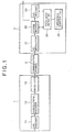
- Fig. 1 is a block diagram showing an exemplary configuration of a communication system which includes a receiver 3 and is capable of transmitting and receiving data at a desired one of plural predetermined data rates.
- a transmitter 1 transmits convolutional coded data to the receiver 3 via a communication channel 2 at a desired one of plural predetermined data rates.
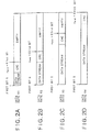
- Fig. 2 shows an exemplary transport format of the data transmitted and received in Fig. 1.
- a CRC code is attached to a data stream. Since the data stream is changed in length in accordance with the data rate, a last bit n end of the CRC code (hereinafter referred to as an end bit position) is different depending on the data rate.
- Fig. 2 For example, in case four data rates R1 to R4 are existent as shown in Fig. 2 (where data rate R1 ⁇ data rate R2 ⁇ data rate R3 ⁇ data rate R4), the last bit n end at the data rate R1, R2, R3 or R4 is Elst bit (Fig. 2A), E2nd bit (Fig. 2B), E3rd bit (Fig. 2C) or E4th bit (Fig. 2D) when counted from a first bit S.
- Fig. 2A the last bit n end at the data rate R1, R2, R3 or R4 is Elst bit (Fig. 2A), E2nd bit (Fig. 2B), E3rd bit (Fig. 2C) or E4th bit (Fig. 2D) when counted from a first bit S.
- the composition is empty from the Elst bit, E2nd bit or E3rd bit, which is the last bit n end at the data rate R1, R2 or R3, to the bit corresponding to the E4th bit which is the last bit n end at the data rate R4.
- the receiver 3 executes Viterbi decoding for the data (Fig. 2) transmitted thereto from the transmitter 1 via the communication channel 2. Further the receiver 3 detects the data rate of the received data and then outputs the decoded data at the detected data rate to an unshown device.
- the transmitter 1 comprises a CRC (cyclic redundancy check) encoder 11, a convolutional encoder 12 and a modulator 13.
- the CRC encoder 11 attaches to the data stream a CRC parity bit of the data to be transmitted, and then supplies the data stream to the convolutional encoder 12.
- the convolutional encoder 12 executes convolutional encoding for the data obtained from the CRC encoder 11, and then supplies the coded data to the modulator 13. Subsequently the modulator 13 modulates the data supplied thereto from the convolutional encoder 12, and transmits the modulated data to the receiver 3 via the communication channel 2.
- the receiver 3 comprises a demodulator 21, a Viterbi decoder 22, a CRC decoder 23 and a data rate detector 24.
- the demodulator 21 demodulates the received data and supplies the demodulated data to the Viterbi decoder 22.
- the Viterbi decoder 22 which is controlled by the data rate detector 24, executes Viterbi decoding for the data obtained from the demodulator 21, and then supplies the resultant data (decoded data) to the CRC decoder 23.
- the Viterbi decoder 22 also supplies, to the data rate detector 24, a maximum pathmetric value, a minimum pathmetric value and a zero-state pathmetric value calculated at this time.
- the Viterbi decoder 22 outputs the resultant Viterbi-decoded data to an unshown device at the data rate detected by the data rate detector 24.
- the CRC decoder 23 which is controlled by the data rate detector 24, executes a CRC decision for the data obtained from the Viterbi decoder 22, and then supplies the result of such a decision to the data rate detector 24.
- the data rate detector 24 controls the Viterbi decoder 22 and the CRC decoder 23 to execute Viterbi decoding and CRC decision respectively, and detects the data rate of the received data on the basis of the maximum pathmetric value, the minimum pathmetric value and the zero-state pathmetric value obtained from the Viterbi decoder 22, and also on the basis of the result of the CRC decision obtained from the CRC decoder 23.
- the data rate detector 24 initializes an internal counter i to 1, a register Smin to D1 which is a predetermined threshold value stored in a threshold register 25, and a register tr to 0, respectively.
- the data rate detector 24 controls the Viterbi decoder 22 to calculate the maximum pathmetric value, the minimum pathmetric value and the zero-state pathmetric value in the range from the first bit S to the last bit n end of the data rate Ri identified by the value of the counter i.
- the Viterbi decoder 22 executes an ACS (add compare select) process including addition, comparison and selection, thereby calculating the maximum pathmetric value, the minimum pathmetric value and the zero-state pathmetric value. Then the Viterbi decoder 22 supplies the calculated data to the data rate detector 24.
- ACS add compare select
- the receiver 3 (data rate detector 24) recognizes the probable data rate Ri in advance and is capable of identifying the data rate Ri by the value of the counter i.
- the maximum pathmetric value, the minimum pathmetric value and the zero-state pathmetric value are calculated in the range from the first bit S to the last Elst (Fig. 2A), E2nd (Fig. 2B), E3rd (Fig. 2C) or E4th (Fig. 2D) bit.
- step S3 the data rate detector 24 executes a calculation of Eq. (1) shown below on the basis of the maximum pathmetric value, minimum pathmetric value and zero-state pathmetric value supplied from the Viterbi decoder 22 at step S2, thereby obtaining an S value.
- S value 10 Log ((a 0 - a min )/((a max - a min ))
- a max denotes the maximum pathmetric value
- a min denotes the minimum pathmetric value
- a 0 denotes a zero-state pathmetric value.
- the maximum of the S value is 0, and the minimum thereof is minus infinite.
- the data rate detector 24 makes a decision as to whether the S value calculated at step S3 is equal to or smaller than the threshold value D1 or not.
- the zero-state pathmetric value calculated in the Viterbi decoder 22 is sufficiently small, so that the S value given by Eq. (1) becomes small. Meanwhile, if the data rate Ri is not the true data rate of the received data, the zero-state pathmetric value calculated in this case is not sufficiently small, so that the S value does not become small. That is, due to the decision of whether the calculated S value is equal to or smaller than the threshold value D1 or not, it becomes possible to make a decision as to whether the data rate Ri identified by the value of the counter i can be regarded or not as the true data rate of the received data (whether there is a probability of the true data rate).
- the threshold value D1 is set to be relatively great so that the S value of the true data rate is not decided to be greater than the threshold value D1.
- step S5 in case the result of the decision at step S4 signifies that the S value is equal to or smaller than the threshold value D1, i.e., when the data rate Ri identified by the value of the counter i at this time can be regarded as the true data rate of the received data (when there is a probability of the true data rate).
- the data rate detector 24 controls the Viterbi decoder 22 to execute a traceback process, thereby generating a data stream which ranges from the first bit S to the last bit n end of the data rate Ri identified by the value of the counter i (e.g., to the Elst bit when the value of the counter i is 1). Subsequently at step S6, the data rate detector 24 controls the CRC decoder 23 to make a CRC decision with respect to the data thus generated.
- the Viterbi decoder 22 generates a data stream ranging from the first bit S to the last bit n end of the data rate Ri, and then supplies the data stream to the CRC decoder 23.
- the CRC decoder 23 divides the decoded data supplied from the Viterbi decoder 22 (i.e., the decoded data from the first bit S to the last bit n end of the data rate Ri) by a generation polynomial, and then finds the remainder thereof.
- the CRC decoder 23 notifies the data rate detector 24 of the remainder as a result of the CRC calculation.
- the data rate detector 24 makes a decision as to whether any error is existent or not in the received data, on the basis of the CRC calculation result obtained from the CRC decoder 23. That is, a decision is made as to whether any error is existent or not in the received data, in accordance with the CRC calculation result obtained when the data rate Ri indicated by the value of the counter i is regarded as the data rate of the received data. And if the CRC calculation result is not zero (i.e., when the data rate Ri is not the true data rate), it is decided that any error is existent. Meanwhile, if the CRC calculation result is zero (i.e., when the data rate Ri is probably the true data rate), it is decided that no error is existent.
- step S7 If the result of the decision at step S7 signifies that no error is existent, the operation proceeds to step S8, where the data rate detector 24 makes a decision as to whether the S value calculated at step S3 is equal to or smaller than the value of the register Smin or not. Since the register Smin is initially set to D1, the S value compared therewith at step S4 and decided first as YES is naturally equal to or smaller than the value of the register Smin.
- step S8 In case the result of the decision at step S8 signifies that the S value is equal to or smaller than the value of the register Smin, the operation proceeds to step S9, where the data rate detector 24 replaces the value of the register Smin with the S value calculated this time. That is, the decision at step S8 is executed to check if the S value calculated this time is the minimum or not out of the entire previous S values obtained heretofore.
- the data rate detector 24 replaces the value of the register tr with that of the counter i obtained this time.
- step S10 if the result of the decision at step S4 signifies that the S value is not equal to or smaller than the threshold value D1, or if the result of the decision at step S7 signifies that some error is existent, or if the result of the decision at step S8 signifies that the S value is not equal to or smaller than the value of the register Smin, or if the values of the registers Smin and tr have been replaced at step S9.
- the data rate detector 24 makes a decision at step S10 as to whether the value of the counter i is maximum (value 4) or not. And if the result of this decision signifies that the counter value is not maximum, the operation proceeds to step S11, where the counter value is increased by 1. Then the operation returns to step S2, and the subsequent processes are executed.
- step S10 the operation proceeds to step S12, where the data rate detector 24 detects the data rate Ri, which is identified by the value of the register tr, as the true data rate of the received data. Then the data rate detector 24 controls the Viterbi decoder 22 to output the decoded data at the detected data rate Ri. The processing routine is thus completed.
- Detecting the data rate of the received data is performed as described above. In this case, calculations of the S value and so forth are executed with respect to the entire data rates R1 to R4 (i.e., the processes at step S2 and subsequent ones are executed). For example, in case the data rate of the received data is R2 and the value of the counter i is 2, the final value of the register tr is determined to be 2. However, the value of the counter i is further increased to 3 and 4, and then the processes at step S2 and subsequent ones are executed.
- the present invention seeks to realize efficient detection of the data rate.
- a signal processing apparatus which comprises an execution means for selecting a plurality of data rates in a predetermined order and executing a maximum likelihood decoding process to regard the data rate of received data as the selected data rate; a calculation means for calculating a predetermined decision value on the basis of a predetermined metric value obtained through the maximum likelihood decoding process; a first decision means for comparing the decision value with a first threshold value, and making a decision, on the basis of the result of such comparison, as to whether the data rate selected by the execution means is the data rate of the received data; a second decision means for comparing the decision value with a second threshold value in response to the result of the decision by the first decision means signifying that the selected data rate is the data rate of the received data, and making another decision, on the basis of the result of such comparison, as to whether the data rate selected by the execution means is the data rate of the received data; and an output means for delivering the output data decoded by the execution means at the data rate selected by the execution means
- a signal processing method which comprises an execution step of selecting a plurality of data rates in a predetermined order and executing a maximum likelihood decoding process to regard the data rate of received data as the selected data rate; a calculation step of calculating a predetermined decision value on the basis of a predetermined metric value obtained through the maximum likelihood decoding process; a first decision step of comparing the decision value with a first threshold value, and making a decision, on the basis of the result of such comparison, as to whether the data rate selected at the execution step is the data rate of the received data; a second decision step of comparing the decision value with a second threshold value in response to the result of the decision at the first decision step signifying that the selected data rate is the data rate of the received data, and making a - decision, on the basis of the result of such comparison, as to whether the data rate selected at the execution step is the data rate of the received data; and an output step of delivering the output data decoded at the execution step at the data rate selected at the data rate selected at
- a recording medium containing a stored program which comprises an execution step of selecting a plurality of data rates in a predetermined order and executing a maximum likelihood decoding process to regard the data rate of received data as the selected data rate; a calculation step of calculating a predetermined decision value on the basis of a predetermined metric value obtained through the maximum likelihood decoding process; a first decision step of comparing the decision value with a first threshold value, and making a decision, on the basis of the result of such comparison, as to whether the data rate selected at the execution step is the data rate of the received data; a second decision step of comparing the decision value with a second threshold value in response to the result of the decision at the first decision step signifying that the selected data rate is the data rate of the received data, and making decision, on the basis of the result of such comparison, as to whether the data rate selected at the execution step is the data rate of the received data; and an output means of delivering the output data decoded at the execution step at the
- a plurality of data rates are selected in a predetermined order, and a maximum likelihood decoding process is executed to regard the data rate of received data as the selected data rate.
- a predetermined decision value is calculated on the basis of a predetermined metric value obtained through the maximum likelihood decoding process, and the decision value is compared with a first threshold value, and then a decision is made, on the basis of the result of such comparison, as to whether the selected data rate is the data rate of the received data.
- the decision value is compared with a second threshold value in response to the result of the decision signifying that the selected data rate is the data rate of the received data, and another decision is made, on the basis of the result of such comparison, as to whether the selected data rate is the data rate of the received data. And in response to the result of the decision signifying that the selected data rate is the data rate of the received data, the decoded data are outputted at the selected data rate.
- Fig. 4 shows a structural example of a communication system including a receiver 51 to which an embodiment of the present invention is applied, wherein data are transmitted and received at a desired one of plural predetermined data rates.
- any component blocks corresponding to those shown in Fig. 1 are denoted by the same reference numerals, and a repeated explanation thereof will be omitted in the following description.
- the receiver 51 has a data rate detector 61 instead of the aforementioned data rate detector 24 in the receiver 3 of Fig. 1, and also has a second threshold register 62 in addition to the aforementioned first threshold register 25.
- the receiver 51 executes Viterbi decoding for the data transmitted thereto from the transmitter 1 via the communication channel 2 (e.g., as in Fig. 2).
- the receiver 51 detects the data rate of the received data through an undermentioned process of data rate detection, and then outputs the decoded data at the detected data rate to an unshown device.
- two threshold values D1 and D2 are stored in separate registers individually, it is a matter of course that D1 and D2 may be stored at separate addresses in one register.
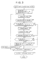
- the data rate detector 61 initializes an internal counter i to 1, a register Smin to D1 which is a predetermined threshold value stored in a threshold register 25, and a register tr to 0, respectively.
- the data rate detector 61 controls the Viterbi decoder 22 to calculate the maximum pathmetric value, the minimum pathmetric value and the zero-state pathmetric value in the range from the first bit S to the last bit n end of the data rate Ri identified by the value of the counter i.
- the Viterbi decoder 22 executes an ACS process including addition, comparison and selection, thereby calculating the maximum pathmetric value, the minimum pathmetric value and the zero-state pathmetric value. Then the Viterbi decoder 22 supplies the calculated data to the data rate detector 61.
- the receiver 51 (data rate detector 61) recognizes the probable data rate Ri in advance and is capable of identifying the data rate Ri by the value of the counter i.
- the data rate detector 61 executes the calculation of Eq. (1) on the basis of the maximum pathmetric value, minimum pathmetric value and zero-state pathmetric value supplied from the Viterbi decoder 22 at step S22, thereby obtaining an S value.
- the data rate detector 61 makes a decision as to whether the S value calculated at step S23 is equal to or smaller than the threshold value D1 or not.
- the operation proceeds to step S25 in case the result of the above decision signifies that the S value is equal to or smaller than the threshold value D1, i.e., when the data rate Ri identified by the value of the counter i at this time can be regarded as the true data rate of the received data (when there is a probability of the true data rate).
- the data rate detector 61 controls the Viterbi decoder 22 to execute a traceback process, thereby generating a data stream which ranges from the first bit S to the last bit n end of the data rate Ri identified by the value of the counter i (e.g., to the Elst bit when the value of the counter i is 1). Subsequently at step S26, the data rate detector 61 controls the CRC decoder 23 to make a CRC decision with respect to the decoded data.
- the Viterbi decoder 22 generates a data stream ranging from the first bit S to the last bit n end of the data rate Ri, and then supplies the data stream to the CRC decoder 23.
- the CRC decoder 23 divides the decoded data supplied from the Viterbi decoder 22 (i.e., the decoded data from the first bit S to the last bit n end of the data rate Ri) by a generation polynomial, then finds the remainder thereof, and notifies the data rate detector 61 of the remainder as a result of the CRC calculation.
- step S27 the data rate detector 61 makes a decision as to whether any error is existent or not in the received data, on the basis of the CRC calculation result obtained from the CRC decoder 23. And if the result of the above decision signifies that no error is existent, the operation proceeds to step S28, where the data rate detector 61 makes a decision as to whether the S value calculated at step S23 is smaller than the threshold value D2 stored in the threshold register 62.
- the threshold value D2 is set to be smaller than the threshold value D1.
- step S28 the operation proceeds to step S29, where the data rate detector 61 replaces the value of the register tr with the value of the counter i obtained this time. Thereafter the operation proceeds to step S30, where the data rate detector 61 detects the data rate Ri, which is identified by the value of the register tr, as the true data rate of the received data. Then the data rate detector 61 controls the Viterbi decoder 22 to output the decoded data at the detected data rate Ri. The processing routine is thus completed.
- step S28 if the result of the decision at step S28 signifies that the S value is not smaller than the threshold value D2, the operation proceeds to step S31, where the data rate detector 61 makes another decision as to whether the S value calculated at step S23 is equal to or smaller than the value of the register Smin. That is, a decision is made as to whether the S value calculated this time is the minimum of the entire S values calculated heretofore.
- step S31 In case the result of the decision at step S31 signifies that the calculated S value is equal to or smaller than the value of the register Smin, the operation proceeds to step S32, where the data rate detector 61 replaces the value of the register Smin with the S value calculated this time. Further the data rate detector 61 replaces the value of the register tr with that of the counter i obtained at this time.
- step S33 if the result of the decision at step S24 signifies that the S value is not equal to or smaller than the threshold value D1, or if the result of the decision at step S27 signifies that any error is existent, or if the result of the decision at step S31 signifies that the S value is not equal to or smaller than the value of the register Smin, or if the values of the registers Smin and tr have been replaced at step S32.
- the data rate detector 61 makes a decision at step S33 as to whether the value of the counter i is maximum (value 4) or not. And if the result of this decision signifies that the counter value is not maximum, the operation proceeds to step S34, where the counter value is increased by 1. Then the operation returns to step S22, and the subsequent processes are executed.
- step S33 in case the result of the decision at step S33 signifies that the value of the counter i is maximum, the operation returns to step S30.
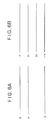
- the S value is compared merely with the threshold value D1 which is relatively great as shown in Fig. 6A, so that it becomes necessary to execute the processes of step S2 and and subsequent ones (Fig. 1) with respect to the entire data rates Ri for detection of the desired data rate Ri having the minimum S value.
- the threshold value D1 which is relatively great as shown in Fig. 6A
- the data rate having such S value is compared also with the threshold value D2 which is proper for regarding the same as the true data rate of the received data.
- the data rate Ri having the S value smaller than the threshold value D2 has been detected (i.e., if the result of the decision at step S28 is affirmative or YES), it is possible to immediately regard the relevant data rate Ri as the true data rate of the received data. Consequently, it is no longer necessary, in embodiments of the present invention, to execute the remaining processes for finding the S value with respect to the other data rates Ri, hence achieving efficient detection of the data rate of the received data.
- the processing routine mentioned above can be carried out by software as well as by hardware.
- a program constituting such software is installed in a computer, and the program is executed by the computer to eventually realize the above-described receiver 51 functionally.
- Fig. 7 is a block diagram showing a structural example of a computer 101 which represents an embodiment to function as the above-described receiver 51.
- An input-output interface 116 is connected to a CPU (central processing unit) 111 via a bus 115.
- the CPU 111 loads into a RAM (random access memory) 113 the program which is stored in a ROM (read only memory) 112, a hard disk 114, or a recording medium mounted on a drive 120, such as a magnetic disk 131, an optical disk 132, a magneto-optical disk 133 or a semiconductor memory 134.
- the CPU 111 executes the program thus loaded, whereby the aforementioned processing routine (e.g., the routine shown in the flowchart of Fig. 5) is carried out. Further the CPU 111 delivers, when necessary, the result via the input-output interface 116 to a display device 117 consisting of an LCD (liquid crystal display) or the like.
- the program may be stored previously in the hard disk 114 or the ROM 112 so as to be provided for the user together with the computer 101, or may be provided as package media including the magnetic disk 131, optical disk 132, magneto-optical disk 133 and semiconductor memory 134, or may be provided to the hard disk 114 from a satellite, network or the like via the communicator 119.
- the steps that describe the program provided by the recording medium are executed in time series in accordance with the mentioned sequence, or may be executed in parallel or individually without being restricted to the time series processing.
Landscapes
- Engineering & Computer Science (AREA)
- Physics & Mathematics (AREA)
- Probability & Statistics with Applications (AREA)
- Theoretical Computer Science (AREA)
- Signal Processing (AREA)
- Computer Networks & Wireless Communication (AREA)
- Artificial Intelligence (AREA)
- Error Detection And Correction (AREA)
- Detection And Correction Of Errors (AREA)
- Detection And Prevention Of Errors In Transmission (AREA)
Applications Claiming Priority (2)
| Application Number | Priority Date | Filing Date | Title |
|---|---|---|---|
| JP2000260211 | 2000-08-30 | ||
| JP2000260211A JP2002076923A (ja) | 2000-08-30 | 2000-08-30 | 信号処理装置および方法、並びに記録媒体 |
Publications (2)
| Publication Number | Publication Date |
|---|---|
| EP1187342A2 true EP1187342A2 (de) | 2002-03-13 |
| EP1187342A3 EP1187342A3 (de) | 2004-02-04 |
Family
ID=18748254
Family Applications (1)
| Application Number | Title | Priority Date | Filing Date |
|---|---|---|---|
| EP01307265A Withdrawn EP1187342A3 (de) | 2000-08-30 | 2001-08-28 | Signalverarbeitungsapparat und Verfahren, und Aufzeichnungsträger |
Country Status (5)
| Country | Link |
|---|---|
| US (1) | US20020025009A1 (de) |
| EP (1) | EP1187342A3 (de) |
| JP (1) | JP2002076923A (de) |
| KR (1) | KR20020018092A (de) |
| CN (1) | CN1340924A (de) |
Cited By (1)
| Publication number | Priority date | Publication date | Assignee | Title |
|---|---|---|---|---|
| EP1206042A3 (de) * | 2000-11-10 | 2004-03-03 | Samsung Electronics Co., Ltd. | Apparat und Verfahren zur Dekodierung von Daten deren Rahmenlänge unbekannt ist |
Families Citing this family (4)
| Publication number | Priority date | Publication date | Assignee | Title |
|---|---|---|---|---|
| JP3852401B2 (ja) | 2002-12-18 | 2006-11-29 | ソニー・エリクソン・モバイルコミュニケーションズ株式会社 | 信号処理装置及び方法 |
| JP5219699B2 (ja) * | 2007-08-30 | 2013-06-26 | パナソニック株式会社 | 符号化装置及び復号装置 |
| WO2009028207A1 (ja) * | 2007-08-30 | 2009-03-05 | Panasonic Corporation | 符号化装置及び復号装置 |
| WO2017160592A1 (en) | 2016-03-18 | 2017-09-21 | Cummins Filtration Ip, Inc. | Interlocked stable filter assembly |
Family Cites Families (3)
| Publication number | Priority date | Publication date | Assignee | Title |
|---|---|---|---|---|
| US5796757A (en) * | 1995-09-15 | 1998-08-18 | Nokia Mobile Phones Ltd. | Methods and apparatus for performing rate determination with a variable rate viterbi decoder |
| US6567466B1 (en) * | 1999-02-16 | 2003-05-20 | Agere Systems Inc. | Method and apparatus for determining the data rate of a received signal in a variable data rate orthogonal spread spectrum communication system |
| JP3613448B2 (ja) * | 1999-06-21 | 2005-01-26 | 株式会社エヌ・ティ・ティ・ドコモ | データ伝送方法、データ伝送システム、送信装置および受信装置 |
-
2000
- 2000-08-30 JP JP2000260211A patent/JP2002076923A/ja not_active Withdrawn
-
2001
- 2001-08-27 US US09/940,555 patent/US20020025009A1/en not_active Abandoned
- 2001-08-28 EP EP01307265A patent/EP1187342A3/de not_active Withdrawn
- 2001-08-28 CN CN01126053A patent/CN1340924A/zh active Pending
- 2001-08-29 KR KR1020010052384A patent/KR20020018092A/ko not_active Withdrawn
Cited By (2)
| Publication number | Priority date | Publication date | Assignee | Title |
|---|---|---|---|---|
| EP1206042A3 (de) * | 2000-11-10 | 2004-03-03 | Samsung Electronics Co., Ltd. | Apparat und Verfahren zur Dekodierung von Daten deren Rahmenlänge unbekannt ist |
| US7450667B2 (en) | 2000-11-10 | 2008-11-11 | Samsung Electronics Co., Ltd. | Apparatus and method for decoding data of unknown frame length |
Also Published As
| Publication number | Publication date |
|---|---|
| KR20020018092A (ko) | 2002-03-07 |
| EP1187342A3 (de) | 2004-02-04 |
| JP2002076923A (ja) | 2002-03-15 |
| US20020025009A1 (en) | 2002-02-28 |
| CN1340924A (zh) | 2002-03-20 |
Similar Documents
| Publication | Publication Date | Title |
|---|---|---|
| RU2216851C2 (ru) | Итеративный декодер и способ итеративного декодирования для коммуникационной системы | |
| US7296209B2 (en) | Apparatus for encoding and decoding | |
| EP1107499B1 (de) | Datenübertragungsverfahren, datenübertragungseinrichtung, sendeinrichtung und empfangseinrichtung | |
| US20080086675A1 (en) | Method and system for ldpc code erasure decoding | |
| JPH05145431A (ja) | ビタビ復号装置 | |
| GB2216755A (en) | A Syndrome Sequential Decoder | |
| CA1320582C (en) | Sequential decoder | |
| KR100212833B1 (ko) | 가변레이트 비터비 복호기 | |
| JP2001024527A (ja) | 受信シンボルのシーケンスを復号化する方法 | |
| EP1187342A2 (de) | Signalverarbeitungsapparat und Verfahren, und Aufzeichnungsträger | |
| US6058501A (en) | Error detecting device for viterbi decoder | |
| JP2004201030A (ja) | 信号処理装置及び方法 | |
| JP2006505983A (ja) | フォーマット検出 | |
| US7085992B2 (en) | Method and device for decoding a sequence of physical signals, reliability detection unit and viterbi decoding unit | |
| US6915474B2 (en) | Turbo decoding apparatus and decoding iteration count controlling method in turbo decoding | |
| US6282691B1 (en) | CRC coding system and CRC coding method | |
| US7173985B1 (en) | Method and apparatus for implementing a Viterbi decoder | |
| US7184409B2 (en) | Blind rate detection method and device in asynchronous mobile communication system | |
| US5402447A (en) | Speech decoding in a zero BER environment | |
| JPH06232768A (ja) | 畳込み符号化データ復号装置 | |
| KR20070034532A (ko) | 확장형 컨벌루션 인코더 디바이스, 무선 시스템, 컨벌루션코드 확장 방법 | |
| US20020124220A1 (en) | Transmission data loss detection system | |
| EP0655843B1 (de) | Empfänger für Digitaldaten mit einem Indexregister für Minimumwert der Kosten | |
| JP2004222196A (ja) | 信号処理装置及び方法 | |
| US20030212949A1 (en) | Apparatus for back-tracking survivor paths of trellis code data and method thereof |
Legal Events
| Date | Code | Title | Description |
|---|---|---|---|
| PUAI | Public reference made under article 153(3) epc to a published international application that has entered the european phase |
Free format text: ORIGINAL CODE: 0009012 |
|
| AK | Designated contracting states |
Kind code of ref document: A2 Designated state(s): AT BE CH CY DE DK ES FI FR GB GR IE IT LI LU MC NL PT SE TR |
|
| AX | Request for extension of the european patent |
Free format text: AL;LT;LV;MK;RO;SI |
|
| PUAL | Search report despatched |
Free format text: ORIGINAL CODE: 0009013 |
|
| AK | Designated contracting states |
Kind code of ref document: A3 Designated state(s): AT BE CH CY DE DK ES FI FR GB GR IE IT LI LU MC NL PT SE TR |
|
| AX | Request for extension of the european patent |
Extension state: AL LT LV MK RO SI |
|
| RIC1 | Information provided on ipc code assigned before grant |
Ipc: 7H 04L 25/02 B Ipc: 7H 04L 1/00 B Ipc: 7H 03M 13/41 A |
|
| AKX | Designation fees paid | ||
| REG | Reference to a national code |
Ref country code: DE Ref legal event code: 8566 |
|
| STAA | Information on the status of an ep patent application or granted ep patent |
Free format text: STATUS: THE APPLICATION IS DEEMED TO BE WITHDRAWN |
|
| 18D | Application deemed to be withdrawn |
Effective date: 20040805 |