EP1186355B1 - Bottle cleaning machine - Google Patents
Bottle cleaning machine Download PDFInfo
- Publication number
- EP1186355B1 EP1186355B1 EP01120680A EP01120680A EP1186355B1 EP 1186355 B1 EP1186355 B1 EP 1186355B1 EP 01120680 A EP01120680 A EP 01120680A EP 01120680 A EP01120680 A EP 01120680A EP 1186355 B1 EP1186355 B1 EP 1186355B1
- Authority
- EP
- European Patent Office
- Prior art keywords
- cleaning machine
- bottle cleaning
- machine according
- eddy
- intake opening
- Prior art date
- Legal status (The legal status is an assumption and is not a legal conclusion. Google has not performed a legal analysis and makes no representation as to the accuracy of the status listed.)
- Expired - Lifetime
Links
- 238000004140 cleaning Methods 0.000 title claims abstract description 24
- 239000003517 fume Substances 0.000 claims 1
- 239000000126 substance Substances 0.000 claims 1
- HEMHJVSKTPXQMS-UHFFFAOYSA-M Sodium hydroxide Chemical compound [OH-].[Na+] HEMHJVSKTPXQMS-UHFFFAOYSA-M 0.000 description 9
- 239000007789 gas Substances 0.000 description 5
- 238000005406 washing Methods 0.000 description 5
- XAGFODPZIPBFFR-UHFFFAOYSA-N aluminium Chemical compound [Al] XAGFODPZIPBFFR-UHFFFAOYSA-N 0.000 description 4
- 229910052782 aluminium Inorganic materials 0.000 description 4
- UFHFLCQGNIYNRP-UHFFFAOYSA-N Hydrogen Chemical compound [H][H] UFHFLCQGNIYNRP-UHFFFAOYSA-N 0.000 description 3
- 238000000605 extraction Methods 0.000 description 2
- 208000035415 Reinfection Diseases 0.000 description 1
- AZDRQVAHHNSJOQ-UHFFFAOYSA-N alumane Chemical group [AlH3] AZDRQVAHHNSJOQ-UHFFFAOYSA-N 0.000 description 1
- 239000007864 aqueous solution Substances 0.000 description 1
- QVGXLLKOCUKJST-UHFFFAOYSA-N atomic oxygen Chemical compound [O] QVGXLLKOCUKJST-UHFFFAOYSA-N 0.000 description 1
- 235000013405 beer Nutrition 0.000 description 1
- 230000015572 biosynthetic process Effects 0.000 description 1
- 239000002775 capsule Substances 0.000 description 1
- 239000007799 cork Substances 0.000 description 1
- 238000009795 derivation Methods 0.000 description 1
- 238000007599 discharging Methods 0.000 description 1
- 230000008030 elimination Effects 0.000 description 1
- 238000003379 elimination reaction Methods 0.000 description 1
- 238000004880 explosion Methods 0.000 description 1
- 238000003197 gene knockdown Methods 0.000 description 1
- 230000035784 germination Effects 0.000 description 1
- 239000001257 hydrogen Substances 0.000 description 1
- 229910052739 hydrogen Inorganic materials 0.000 description 1
- 239000000203 mixture Substances 0.000 description 1
- 239000001301 oxygen Substances 0.000 description 1
- 229910052760 oxygen Inorganic materials 0.000 description 1
- 238000005192 partition Methods 0.000 description 1
Images
Classifications
-
- B—PERFORMING OPERATIONS; TRANSPORTING
- B08—CLEANING
- B08B—CLEANING IN GENERAL; PREVENTION OF FOULING IN GENERAL
- B08B15/00—Preventing escape of dirt or fumes from the area where they are produced; Collecting or removing dirt or fumes from that area
-
- B—PERFORMING OPERATIONS; TRANSPORTING
- B08—CLEANING
- B08B—CLEANING IN GENERAL; PREVENTION OF FOULING IN GENERAL
- B08B9/00—Cleaning hollow articles by methods or apparatus specially adapted thereto
- B08B9/08—Cleaning containers, e.g. tanks
- B08B9/20—Cleaning containers, e.g. tanks by using apparatus into or on to which containers, e.g. bottles, jars, cans are brought
Definitions
- the invention relates to a bottle cleaning machine with an up and Dispensing station and several arranged in the direction of flow of the bottles treatment stations and a suction channel for steam or other air masses.
- Container washing machines in particular high-performance washing machines for the cellar industry
- Laugenstation a so-called Laugenstation on, immersed in the container to be cleaned in a tub which is filled with cleaning liquor.
- an aqueous Solution of NaOH used as lye.
- the tub is heated to the lye temperature to, for example, 80 ° C hold.
- To be cleaned containers often have aluminum equipment.
- one-liter liter crown cork beer bottles are usually in the head area with one so-called aluminum capsule provided, the largest part of the cleaning yet is available.
- Even labels may consist entirely or partially of aluminum.
- the object of the invention is to provide a device with which in a cleaning machine accumulated and to be eliminated air masses more targeted and broader sucked and can be derived.
- suction channel runs transversely to the direction of movement of the bottles and as a vortex hood is formed with a Vorbelsenkenabsaugung.
- the formation of the invention is a particularly advantageous derivation of gases to be removed from the housing of a bottle washing machine, Swaths, air masses and the like. guaranteed.
- the air masses can be fast and targeted on the entire width of the longitudinal or transversely installed suction ducts are detected and derived by this.
- the Throughput of the suction duct is the machine performance appropriate automatically adaptable.
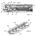
- a bottle washer with the feeding station 1 and the dispensing station 2 shown.
- the bottles 3 are in bottle cells 4 by the individual cleaning departments 5,6 out and in the area of the dispensing station 2, for example, by rotating discharge surfaces underpinned and down to discontinued or pushed onto a drain conveyor.
- a steam extraction duct 7 arranged, the inside wall is practically used as a partition for Machine housing 8 may be formed.
- suction channels 9,10 in the individual treatment zones and divisions 5,6 of such a cleaning machine be provided.
- suction 7.7 'with a slit-shaped suction port 11 which according to the embodiment runs transversely to the bottle conveying direction. But this can also be longitudinal to the bottle conveying direction run.
- the suction port 11 is part of a swirling flow generating vortex hood 12, which at least laterally on one side a support tube 13 for discharging the sucked air masses.
- a swirling flow generating vortex hood 12 which at least laterally on one side a support tube 13 for discharging the sucked air masses.
- very wide cleaning machines or long vortex hoods 12 can laterally provided on both sides and also in the middle of the vortex hood 12 more support tubes 13 be.
- the gap width of the intake passage 7 may be adjustable and depending on the machine throughput can be changed.
- At least a portion of the vortex hood 12 can directly shape the housing or part of the housing. Incidentally, any cross-sectional shapes can be provided be.
Landscapes
- Engineering & Computer Science (AREA)
- Mechanical Engineering (AREA)
- Cleaning In General (AREA)
- Centrifugal Separators (AREA)
Abstract
Description
Die Erfindung bezieht sich auf eine Flaschenreinigungsmaschine mit einer Auf- und Abgabestation und mehreren in Durchlaufrichtung der Flaschen angeordneten Behandlungsstationen sowie einem Absaugkanal für Schwaden oder andere Luftmassen.The invention relates to a bottle cleaning machine with an up and Dispensing station and several arranged in the direction of flow of the bottles treatment stations and a suction channel for steam or other air masses.
Es ist bekannt, den Schwaden, der im Inneren von Flaschenreinigungsmaschinen verstärkt auftritt, vor der Flaschenabgabe durch entsprechende Kaltwassernachspritzungen niederzuschlagen oder den Schwaden noch vor .der Flaschenabgabe aus dem Inneren der Maschine abzusaugen. Hierzu sind Abzugskanäle vorgesehen, die unter Einbindung eines Ventilators den im Maschinenbereich anfallenden Schwaden ansaugen und ins Freie abführen. Solche Kanäle sind meist unmittelbar vor dem Austritt der Flaschen aus der Reinigungsmaschine angeordnet, wodurch die im Abgabebereich anstehende Luft ebenfalls angesaugt und über die abgegebenen Flaschen hinweg in das Innere der Maschine geleitet wird. So eine Absaugseinrichtung ist von Dokument EP-A-0 590 509 bekannt. Diese meist biologisch nicht einwandfreie Luft gelangt dabei auch in den Bereich der Flaschen und kann durch ihre Keimhaltigkeit möglicherweise zu einer Reinfektion der befüllten Flaschen führen.It is well known the swaths inside of bottle washing machines occurs more intensively, before the bottle delivery by appropriate Kaltwassernachspritzungen knock down or the swaths before. The bottle delivery to suck the inside of the machine. For this purpose, discharge channels are provided, the with the involvement of a fan, the swaths occurring in the machine area suck in and remove to the outside. Such channels are usually immediately before Exit of the bottles from the cleaning machine arranged, whereby the in the delivery area Pending air sucked in and over the bottles delivered into the interior of the machine. Such a suction device is of document EP-A-0 590 509 known. These are not usually biological impeccable air gets into the area of the bottles and can through their germination may possibly lead to reinfection of the filled bottles.
Behälterwaschmaschinen, insbesondere Hochleistungswaschmaschinen für die Kellereiindustrie, weisen schließlich als wesentliche Reinigungsstation eine sogenannte Laugenstation auf, in der die zu reinigenden Behälter in einen Laugenbehälter eingetaucht werden, der mit Reinigungslauge gefüllt ist. Üblicherweise wird eine wäßrige Lösung von NaOH als Lauge verwendet. Zur Steigerung der Reinigungswirkung ist der Laugenbehälter beheizt, um die Laugentemperatur auf beispielsweise 80°C zu halten.Container washing machines, in particular high-performance washing machines for the cellar industry, Finally, as an essential cleaning station a so-called Laugenstation on, immersed in the container to be cleaned in a tub which is filled with cleaning liquor. Usually, an aqueous Solution of NaOH used as lye. To increase the cleaning effect the tub is heated to the lye temperature to, for example, 80 ° C hold.
Zu reinigende Behälter weisen häufig Aluminiumausstattungen auf. Beispielsweise sind Eindrittelliter-Kronkorkenbierflaschen üblicherweise im Kopfbereich mit einer sogenannten Aluminiumkapsel versehen, deren größter Teil bei der Reinigung noch vorhanden ist. Auch Etiketten können ganz oder teilweise aus Aluminium bestehen. To be cleaned containers often have aluminum equipment. For example For example, one-liter liter crown cork beer bottles are usually in the head area with one so-called aluminum capsule provided, the largest part of the cleaning yet is available. Even labels may consist entirely or partially of aluminum.
Aluminium wird in Lauge, insbesondere in heißer Lauge, schnell aufgelöst. Dieser Effekt ist zur Entfernung der Aluminiumreste durchaus erwünscht. Es entsteht dabei aber Wasserstoffgas (H2), das aus der Lauge in den darüber befindlichen Gasraum entweicht. Mit dem dort vorhandenen Luftsauerstoff bildet sich dann sehr schnell (bei H2-Konzentrationen oberhalb etwa 4%) ein zündfähiges Knallgasgemisch, das heftige Explosionen hervorrufen kann.Aluminum is rapidly dissolved in lye, especially in hot liquor. This effect is quite desirable for removing the aluminum residues. However, it produces hydrogen gas (H 2 ), which escapes from the liquor into the gas space above it. With the atmospheric oxygen present there then forms very quickly (at H 2 concentrations above about 4%) an ignitable oxyhydrogen gas mixture, which can cause violent explosions.
Im Stand der Technik sind daher Wasserstoffbeseitigungseinrichtungen bekannt, die aus Sicherheitsgründen zwingend erforderlich sind. Bei den bekannten Behälterwaschmaschinen der eingangs genannten Art sind zur Beseitigung des Wasserstoffgases Absaugeinrichtungen vorgesehen, die unter Ansaugen von Frischluft Gas aus dem Gasraum über dem Laugenbehälter absaugen und ins Freie blasen.In the prior art, therefore, hydrogen removal devices are known which for safety reasons are absolutely necessary. In the known container washing machines of the type mentioned are for the elimination of the hydrogen gas Extraction devices provided, the under suction of fresh air gas Extract the gas space above the tub and blow into the air.
Aufgabe der Erfindung ist es, eine Vorrichtung aufzuzeigen, mit der die in einer Reinigungsmaschine anfallenden und zu beseitigenden Luftmassen gezielter und breitflächiger angesaugt und abgeleitet werden können.The object of the invention is to provide a device with which in a cleaning machine accumulated and to be eliminated air masses more targeted and broader sucked and can be derived.
Diese Aufgabe wird bei einer Flaschenreinigungsmaschine der eingangs genannten Art dadurch gelöst, daß der Absaugkanal mindestens teilweise mit einer schlitzförmigen Ansaugöffnung ausgebildet ist, die quer und/oder längs im Reinigungsmaschinengehäuse verläuft und als Teil einer eine Drallströmung erzeugenden Wirbelhaube ausgebildet ist.This object is achieved in a bottle cleaning machine of the aforementioned Art solved by the fact that the suction channel at least partially with a slot-shaped Suction opening is formed, the transverse and / or longitudinal in the cleaning machine housing runs and as part of a vortex flow generating vortex hood is trained.
In selbständiger Ausbildung der Erfindung wird ferner vorgeschlagen, daß der Absaugkanal quer zur Bewegungsrichtung der Flaschen verläuft und als Wirbelhaube mit einer Wirbelsenkenabsaugung ausgebildet ist.In independent training of the invention is also proposed that the suction channel runs transversely to the direction of movement of the bottles and as a vortex hood is formed with a Vorbelsenkenabsaugung.
Mit der erfindungsgemäßen Ausbildung ist eine besonders vorteilhafte Ableitung der aus dem Gehäuse einer Flaschenreinigungsmaschine zu entfernenden Gase, Schwaden, Luftmassen u.dgl. gewährleistet. Durch die aufgezeigte Ausführungsform können die Luftmassen schnell und gezielt auf der gesamten Breite des längs oder quer installierten Absaugkanals erfaßt und durch diesen abgeleitet werden. Die Durchsatzleistung des Absaugkanals ist der Maschinenleistung zweckmäßig automatisch anpaßbar. With the formation of the invention is a particularly advantageous derivation of gases to be removed from the housing of a bottle washing machine, Swaths, air masses and the like. guaranteed. By the embodiment shown The air masses can be fast and targeted on the entire width of the longitudinal or transversely installed suction ducts are detected and derived by this. The Throughput of the suction duct is the machine performance appropriate automatically adaptable.
Im nachfolgenden wird die Erfindung anhand eines in Fig. 1 und 2 der Zeichnung dargestellten Ausführungsbeispiels näher erläutert.In the following the invention with reference to a in Figs. 1 and 2 of the drawing illustrated embodiment illustrated.
In der Zeichnung ist eine Flaschenreinigungsmaschine mit der Aufgabestation 1 und
der Abgabestation 2 dargestellt. Die Flaschen 3 werden in Flaschenzellen 4 durch
die einzelnen Reinigungsabteilungen 5,6 geführt und im Bereich der Abgabestation
2, beispielsweise durch rotierende Abgabeflächen unterfangen und nach unten auf
einen Ablauftransporteur abgesetzt bzw. auf diesen abgedrängt. Gemäß dem dargestellten
Ausführungsbeispiel ist kopfseitig an der Abgabestation 2 ein Schwadenabzugskanal
7 angeordnet, dessen innenseitige Wand praktisch als Trennwand zum
Maschinengehäuse 8 ausgebildet sein kann.In the drawing is a bottle washer with the feeding station 1 and
the
Wie aus der Zeichnung Figur 1 ersichtlich, können weitere Absaugkanäle 9,10 in den
einzelnen Behandlungszonen und -Abteilungen 5,6 einer solchen Reinigungsmaschine
vorgesehen sein. Zweckmäßig ist dabei der Absaugkanal 7,7' mit einer
schlitzförmigen Ansaugöffnung 11 ausgestattet, die gemäß dem Ausführungsbeispiel
quer zur Flaschenförderrichtung verläuft. Diese kann aber auch längs zur Flaschenförderrichtung
verlaufen. Die Ansaugöffnung 11 ist dabei als Teil einer eine Drallströmung
erzeugende Wirbelhaube 12 ausgebildet, die mindestens seitlich einseitig
ein Stützrohr 13 zur Ableitung der angesaugten Luftmassen aufweist. Insbesondere
bei sehr breiten Reinigungsmaschinen oder langen Wirbelhauben 12 können seitlich
auf beiden Seiten und auch mittig der Wirbelhaube 12 weitere Stützrohre 13 vorgesehen
sein.As can be seen from the drawing Figure 1, further suction channels 9,10 in the
individual treatment zones and
Die Spaltbreite des Ansaugkanals 7 kann einstellbar sein und in Abhängigkeit von
der Maschinendurchsatzleistung verändert werden.The gap width of the
Je nach Ausbildung des Reinigungsmaschinengehäuses 8 und dort, wo es sich anbietet,
kann mindestens ein Teil der Wirbelhaube 12 direkt das Gehäuse mitgestalten
oder Teil des Gehäuses sein. Im übrigen können beliebige Querschnittsformen vorgesehen
sein.Depending on the design of the cleaning machine housing 8 and where it lends itself,
At least a portion of the
Claims (6)
- Bottle cleaning machine provided with a loading station and an unloading station and a plurality of treatment stations, disposed in the direction of the movement of the bottles, as well as at least one suction duct for fumes and/or other air substances, characterised in that the suction duct is configured at least partially with a slit-shaped intake opening (7, 7'), which extends transversely and/or longitudinally in the cleaning machine housing (8) and is in the form of a portion of an eddy cover (12) generating a swirling current.
- Bottle cleaning machine according to the main preamble of claim 1, characterised in that the suction duct (7, 7') extends transversely relative to the direction of movement of the bottles and is in the form of an eddy cover (12) provided with an eddy reducing suction means.
- Bottle cleaning machine according to the preceding claims, characterised in that the clearance of the slit-shaped intake opening (7, 7') is changeable.
- Bottle cleaning machine according to the preceding claims, characterised in that the clearance of the slit-shaped intake opening (7, 7') is changeable in a manual and/or motor-driven manner in dependence on the machine throughput rate.
- Bottle cleaning machine according to the preceding claims, characterised in that a support pipe (13) for conducting away the inducted air is provided at least laterally on one side and/or centrally.
- Bottle cleaning machine according to the preceding claims, characterised in that at least one portion of the eddy cover (12) is formed from housing parts (8) of the cleaning machine.
Applications Claiming Priority (2)
| Application Number | Priority Date | Filing Date | Title |
|---|---|---|---|
| DE10045083A DE10045083A1 (en) | 2000-09-12 | 2000-09-12 | Bottle washer |
| DE10045083 | 2000-09-12 |
Publications (3)
| Publication Number | Publication Date |
|---|---|
| EP1186355A2 EP1186355A2 (en) | 2002-03-13 |
| EP1186355A3 EP1186355A3 (en) | 2003-08-20 |
| EP1186355B1 true EP1186355B1 (en) | 2004-07-21 |
Family
ID=7655933
Family Applications (1)
| Application Number | Title | Priority Date | Filing Date |
|---|---|---|---|
| EP01120680A Expired - Lifetime EP1186355B1 (en) | 2000-09-12 | 2001-09-03 | Bottle cleaning machine |
Country Status (3)
| Country | Link |
|---|---|
| EP (1) | EP1186355B1 (en) |
| AT (1) | ATE271427T1 (en) |
| DE (2) | DE10045083A1 (en) |
Family Cites Families (4)
| Publication number | Priority date | Publication date | Assignee | Title |
|---|---|---|---|---|
| GB514293A (en) * | 1937-05-06 | 1939-11-03 | Cherry Burrell Corp | Improvements in or relating to machines for washing bottles or similar containers |
| US4208761A (en) * | 1978-01-24 | 1980-06-24 | New England Machinery, Inc. | Bottle conveying and cleaning apparatus |
| DE3914412A1 (en) * | 1989-04-29 | 1990-10-31 | Seitz Enzinger Noll Masch | Heat recycling system for bottle cleaning machines - has two circuits with heat exchangers, hydrogen gas suction unit and fluid pipe to remove condensation |
| DE4232986C2 (en) * | 1992-10-01 | 1996-10-31 | Khs Masch & Anlagenbau Ag | Bottle washer with a loading and unloading station |
-
2000
- 2000-09-12 DE DE10045083A patent/DE10045083A1/en not_active Withdrawn
-
2001
- 2001-09-03 AT AT01120680T patent/ATE271427T1/en not_active IP Right Cessation
- 2001-09-03 EP EP01120680A patent/EP1186355B1/en not_active Expired - Lifetime
- 2001-09-03 DE DE50102907T patent/DE50102907D1/en not_active Expired - Lifetime
Also Published As
| Publication number | Publication date |
|---|---|
| DE10045083A1 (en) | 2002-03-28 |
| EP1186355A2 (en) | 2002-03-13 |
| ATE271427T1 (en) | 2004-08-15 |
| EP1186355A3 (en) | 2003-08-20 |
| DE50102907D1 (en) | 2004-08-26 |
Similar Documents
| Publication | Publication Date | Title |
|---|---|---|
| DE102011119171B3 (en) | Apparatus for treating containers with a suction device | |
| DE2612958A1 (en) | DEVICE FOR REMOVING OXYGEN FROM PACKAGING CONTAINERS | |
| DE10207499A1 (en) | Pipette tip or dispensing unit cleansing system, involves introducing pipette tip into a cleaning chamber, and spraying with a cleaning fluid | |
| WO2010037356A1 (en) | Filling method and device | |
| EP3067126B1 (en) | Device for flushing a container with a flushing medium | |
| EP1692072B1 (en) | Container treatment device with a gas curtain | |
| EP2688689B1 (en) | Device for blowing off bottle bottoms | |
| DE102020129774A1 (en) | Device for conveying and cleaning small parts with an open cavity | |
| DE2645464C2 (en) | Device for the direct conveyance of light objects in a channel | |
| DE10045083A1 (en) | Bottle washer | |
| EP1513761B1 (en) | Device for removing extraneous air from a clean room | |
| DE102008049296A1 (en) | Blowing or drying device for container i.e. box, has drying station with nozzle head, which is insertable for blowing and/or sucking into container, where nozzle head is movable relative to container arranged at respective drying station | |
| AT396737B (en) | DEVICE FOR SEPARATING FUME, FAT AND DUST PARTICLES FROM AN AIRFLOW | |
| DE60026397T2 (en) | Vacuum cleaner with liquid bath | |
| EP0387526B1 (en) | Apparatus for the electrolytic treatment of work-pieces through a succession of baths | |
| DE19916233C1 (en) | Rolling mill stand for cold rolling steel strip, which is enclosed by housing with air inlet and outlet openings for directional air flow through it | |
| DE4203786A1 (en) | Removing pieces of broken bottles in filling machine - using circulating rotor with fittings which do not rotate with it for removal of glass pieces from bottle carrier | |
| DE3145168A1 (en) | Apparatus for the automatic brushing-off of bottle caps | |
| EP1226087B1 (en) | Foaming device for beverage containers | |
| DE19733582B4 (en) | Method and device for treating bottles or the like in a liquid bath | |
| DE4035786A1 (en) | BLOW HEAD OF A DEVICE FOR WASHING SEMICONDUCTOR MATERIALS | |
| DE1801797A1 (en) | Bottle washing machine | |
| EP0590509B1 (en) | Bottle cleaning machine with a load and an unload section | |
| WO2023089004A1 (en) | Air blade device | |
| DE3939601A1 (en) | DEVICE FOR DRYING SMALL PARTS |
Legal Events
| Date | Code | Title | Description |
|---|---|---|---|
| PUAI | Public reference made under article 153(3) epc to a published international application that has entered the european phase |
Free format text: ORIGINAL CODE: 0009012 |
|
| 17P | Request for examination filed |
Effective date: 20010926 |
|
| AK | Designated contracting states |
Kind code of ref document: A2 Designated state(s): AT BE CH CY DE DK ES FI FR GB GR IE IT LI LU MC NL PT SE TR |
|
| AX | Request for extension of the european patent |
Free format text: AL;LT;LV;MK;RO;SI |
|
| PUAL | Search report despatched |
Free format text: ORIGINAL CODE: 0009013 |
|
| AK | Designated contracting states |
Designated state(s): AT BE CH CY DE DK ES FI FR GB GR IE IT LI LU MC NL PT SE TR |
|
| AX | Request for extension of the european patent |
Extension state: AL LT LV MK RO SI |
|
| GRAP | Despatch of communication of intention to grant a patent |
Free format text: ORIGINAL CODE: EPIDOSNIGR1 |
|
| GRAS | Grant fee paid |
Free format text: ORIGINAL CODE: EPIDOSNIGR3 |
|
| AKX | Designation fees paid |
Designated state(s): AT BE CH CY DE DK ES FI FR GB GR IE IT LI LU MC NL PT SE TR |
|
| GRAA | (expected) grant |
Free format text: ORIGINAL CODE: 0009210 |
|
| AK | Designated contracting states |
Kind code of ref document: B1 Designated state(s): AT BE CH CY DE DK ES FI FR GB GR IE IT LI LU MC NL PT SE TR |
|
| PG25 | Lapsed in a contracting state [announced via postgrant information from national office to epo] |
Ref country code: CY Free format text: LAPSE BECAUSE OF FAILURE TO SUBMIT A TRANSLATION OF THE DESCRIPTION OR TO PAY THE FEE WITHIN THE PRESCRIBED TIME-LIMIT Effective date: 20040721 Ref country code: TR Free format text: LAPSE BECAUSE OF FAILURE TO SUBMIT A TRANSLATION OF THE DESCRIPTION OR TO PAY THE FEE WITHIN THE PRESCRIBED TIME-LIMIT Effective date: 20040721 Ref country code: FI Free format text: LAPSE BECAUSE OF FAILURE TO SUBMIT A TRANSLATION OF THE DESCRIPTION OR TO PAY THE FEE WITHIN THE PRESCRIBED TIME-LIMIT Effective date: 20040721 Ref country code: IE Free format text: LAPSE BECAUSE OF FAILURE TO SUBMIT A TRANSLATION OF THE DESCRIPTION OR TO PAY THE FEE WITHIN THE PRESCRIBED TIME-LIMIT Effective date: 20040721 |
|
| REG | Reference to a national code |
Ref country code: GB Ref legal event code: FG4D Free format text: NOT ENGLISH |
|
| REG | Reference to a national code |
Ref country code: CH Ref legal event code: EP |
|
| GBT | Gb: translation of ep patent filed (gb section 77(6)(a)/1977) |
Effective date: 20040721 |
|
| REG | Reference to a national code |
Ref country code: IE Ref legal event code: FG4D Free format text: GERMAN |
|
| REF | Corresponds to: |
Ref document number: 50102907 Country of ref document: DE Date of ref document: 20040826 Kind code of ref document: P |
|
| PG25 | Lapsed in a contracting state [announced via postgrant information from national office to epo] |
Ref country code: LU Free format text: LAPSE BECAUSE OF NON-PAYMENT OF DUE FEES Effective date: 20040903 Ref country code: AT Free format text: LAPSE BECAUSE OF NON-PAYMENT OF DUE FEES Effective date: 20040903 |
|
| PG25 | Lapsed in a contracting state [announced via postgrant information from national office to epo] |
Ref country code: MC Free format text: LAPSE BECAUSE OF NON-PAYMENT OF DUE FEES Effective date: 20040930 |
|
| PG25 | Lapsed in a contracting state [announced via postgrant information from national office to epo] |
Ref country code: DK Free format text: LAPSE BECAUSE OF FAILURE TO SUBMIT A TRANSLATION OF THE DESCRIPTION OR TO PAY THE FEE WITHIN THE PRESCRIBED TIME-LIMIT Effective date: 20041021 Ref country code: GR Free format text: LAPSE BECAUSE OF FAILURE TO SUBMIT A TRANSLATION OF THE DESCRIPTION OR TO PAY THE FEE WITHIN THE PRESCRIBED TIME-LIMIT Effective date: 20041021 Ref country code: SE Free format text: LAPSE BECAUSE OF FAILURE TO SUBMIT A TRANSLATION OF THE DESCRIPTION OR TO PAY THE FEE WITHIN THE PRESCRIBED TIME-LIMIT Effective date: 20041021 |
|
| PG25 | Lapsed in a contracting state [announced via postgrant information from national office to epo] |
Ref country code: ES Free format text: LAPSE BECAUSE OF FAILURE TO SUBMIT A TRANSLATION OF THE DESCRIPTION OR TO PAY THE FEE WITHIN THE PRESCRIBED TIME-LIMIT Effective date: 20041101 |
|
| REG | Reference to a national code |
Ref country code: IE Ref legal event code: FD4D |
|
| ET | Fr: translation filed | ||
| PLBE | No opposition filed within time limit |
Free format text: ORIGINAL CODE: 0009261 |
|
| STAA | Information on the status of an ep patent application or granted ep patent |
Free format text: STATUS: NO OPPOSITION FILED WITHIN TIME LIMIT |
|
| 26N | No opposition filed |
Effective date: 20050422 |
|
| PG25 | Lapsed in a contracting state [announced via postgrant information from national office to epo] |
Ref country code: CH Free format text: LAPSE BECAUSE OF NON-PAYMENT OF DUE FEES Effective date: 20050930 Ref country code: LI Free format text: LAPSE BECAUSE OF NON-PAYMENT OF DUE FEES Effective date: 20050930 |
|
| REG | Reference to a national code |
Ref country code: CH Ref legal event code: PL |
|
| REG | Reference to a national code |
Ref country code: FR Ref legal event code: ST Effective date: 20070531 |
|
| REG | Reference to a national code |
Ref country code: FR Ref legal event code: RN |
|
| REG | Reference to a national code |
Ref country code: FR Ref legal event code: FC |
|
| PG25 | Lapsed in a contracting state [announced via postgrant information from national office to epo] |
Ref country code: PT Free format text: LAPSE BECAUSE OF NON-PAYMENT OF DUE FEES Effective date: 20041221 |
|
| PG25 | Lapsed in a contracting state [announced via postgrant information from national office to epo] |
Ref country code: FR Free format text: LAPSE BECAUSE OF NON-PAYMENT OF DUE FEES Effective date: 20061002 |
|
| PGRI | Patent reinstated in contracting state [announced from national office to epo] |
Ref country code: FR Effective date: 20071017 |
|
| REG | Reference to a national code |
Ref country code: NL Ref legal event code: TD Effective date: 20111114 |
|
| REG | Reference to a national code |
Ref country code: FR Ref legal event code: CD Owner name: KHS GMBH Effective date: 20111121 Ref country code: FR Ref legal event code: CD Owner name: KHS GMBH Effective date: 20111122 |
|
| BECN | Be: change of holder's name |
Owner name: KHS G.M.B.H. Effective date: 20120314 |
|
| REG | Reference to a national code |
Ref country code: FR Ref legal event code: PLFP Year of fee payment: 16 |
|
| REG | Reference to a national code |
Ref country code: FR Ref legal event code: PLFP Year of fee payment: 17 |
|
| PGFP | Annual fee paid to national office [announced via postgrant information from national office to epo] |
Ref country code: GB Payment date: 20170921 Year of fee payment: 17 |
|
| PGFP | Annual fee paid to national office [announced via postgrant information from national office to epo] |
Ref country code: NL Payment date: 20170921 Year of fee payment: 17 |
|
| REG | Reference to a national code |
Ref country code: FR Ref legal event code: PLFP Year of fee payment: 18 |
|
| REG | Reference to a national code |
Ref country code: NL Ref legal event code: MM Effective date: 20181001 |
|
| GBPC | Gb: european patent ceased through non-payment of renewal fee |
Effective date: 20180903 |
|
| PG25 | Lapsed in a contracting state [announced via postgrant information from national office to epo] |
Ref country code: NL Free format text: LAPSE BECAUSE OF NON-PAYMENT OF DUE FEES Effective date: 20181001 |
|
| PG25 | Lapsed in a contracting state [announced via postgrant information from national office to epo] |
Ref country code: GB Free format text: LAPSE BECAUSE OF NON-PAYMENT OF DUE FEES Effective date: 20180903 |
|
| PGFP | Annual fee paid to national office [announced via postgrant information from national office to epo] |
Ref country code: FR Payment date: 20200914 Year of fee payment: 20 Ref country code: DE Payment date: 20200925 Year of fee payment: 20 |
|
| PGFP | Annual fee paid to national office [announced via postgrant information from national office to epo] |
Ref country code: BE Payment date: 20200925 Year of fee payment: 20 Ref country code: IT Payment date: 20200922 Year of fee payment: 20 |
|
| REG | Reference to a national code |
Ref country code: DE Ref legal event code: R071 Ref document number: 50102907 Country of ref document: DE |
|
| REG | Reference to a national code |
Ref country code: BE Ref legal event code: MK Effective date: 20210903 |