EP1186275A1 - Implant dentaire et prothèse - Google Patents
Implant dentaire et prothèse Download PDFInfo
- Publication number
- EP1186275A1 EP1186275A1 EP00119812A EP00119812A EP1186275A1 EP 1186275 A1 EP1186275 A1 EP 1186275A1 EP 00119812 A EP00119812 A EP 00119812A EP 00119812 A EP00119812 A EP 00119812A EP 1186275 A1 EP1186275 A1 EP 1186275A1
- Authority
- EP
- European Patent Office
- Prior art keywords
- implant
- jaw
- thread
- external thread
- jaw implant
- Prior art date
- Legal status (The legal status is an assumption and is not a legal conclusion. Google has not performed a legal analysis and makes no representation as to the accuracy of the status listed.)
- Granted
Links
Images


Classifications
-
- A—HUMAN NECESSITIES
- A61—MEDICAL OR VETERINARY SCIENCE; HYGIENE
- A61C—DENTISTRY; APPARATUS OR METHODS FOR ORAL OR DENTAL HYGIENE
- A61C8/00—Means to be fixed to the jaw-bone for consolidating natural teeth or for fixing dental prostheses thereon; Dental implants; Implanting tools
- A61C8/0048—Connecting the upper structure to the implant, e.g. bridging bars
-
- A—HUMAN NECESSITIES
- A61—MEDICAL OR VETERINARY SCIENCE; HYGIENE
- A61C—DENTISTRY; APPARATUS OR METHODS FOR ORAL OR DENTAL HYGIENE
- A61C8/00—Means to be fixed to the jaw-bone for consolidating natural teeth or for fixing dental prostheses thereon; Dental implants; Implanting tools
- A61C8/0018—Means to be fixed to the jaw-bone for consolidating natural teeth or for fixing dental prostheses thereon; Dental implants; Implanting tools characterised by the shape
- A61C8/0022—Self-screwing
-
- A—HUMAN NECESSITIES
- A61—MEDICAL OR VETERINARY SCIENCE; HYGIENE
- A61C—DENTISTRY; APPARATUS OR METHODS FOR ORAL OR DENTAL HYGIENE
- A61C8/00—Means to be fixed to the jaw-bone for consolidating natural teeth or for fixing dental prostheses thereon; Dental implants; Implanting tools
- A61C8/0048—Connecting the upper structure to the implant, e.g. bridging bars
- A61C8/005—Connecting devices for joining an upper structure with an implant member, e.g. spacers
- A61C8/0069—Connecting devices for joining an upper structure with an implant member, e.g. spacers tapered or conical connection
-
- A—HUMAN NECESSITIES
- A61—MEDICAL OR VETERINARY SCIENCE; HYGIENE
- A61C—DENTISTRY; APPARATUS OR METHODS FOR ORAL OR DENTAL HYGIENE
- A61C8/00—Means to be fixed to the jaw-bone for consolidating natural teeth or for fixing dental prostheses thereon; Dental implants; Implanting tools
- A61C8/0048—Connecting the upper structure to the implant, e.g. bridging bars
- A61C8/005—Connecting devices for joining an upper structure with an implant member, e.g. spacers
- A61C8/0068—Connecting devices for joining an upper structure with an implant member, e.g. spacers with an additional screw
Definitions
- the invention relates to a jaw implant for a denture according to the preamble of claim 1 and a denture according to the preamble of claim 11.
- Natural teeth experience various impairments over time, for example due to poor oral hygiene, age-related wear and tear or accidents. These impairments manifest themselves as damage to individual tooth areas Teeth or as the absence of whole teeth and groups of teeth. Conventionally missing areas of teeth replaced by onlays, inlays or crowns, and missing teeth or tooth groups are replaced either by bridges or by prostheses. onlays, Inlays and crowns are firmly attached to the remaining tooth while bridges firmly attached to the still existing adjacent to the missing teeth and groups of teeth Teeth are mounted. Prostheses are for daily cleaning and for rest at night removable and are either attached to still existing dental material or are designed so that they are supported on the jaw and palate by their shape.
- a serious disadvantage is the need to see what still exists and in general sacrifice healthy dental material.
- the area where a dental prosthesis is too must be prepared beforehand.
- Tooth material of the rest of the tooth to be supplemented or of the adjacent teeth grinding replacement teeth or groups of teeth Once tooth material is removed is not reproduced by the body, every removal of healthy tooth material of course undesirable and should be avoided if possible, especially with regard to further tooth repairs in the same jaw area, which are usually necessary after some time because the tooth replacement parts are subject to a certain amount of wear, of additional tooth material.
- tooth groups of two or more adjacent teeth have to be replaced, this means that not every tooth to be replaced has its own replacement tooth root; it must a jaw implant cannot therefore be provided at every point of a tooth to be replaced, two jaw implants are generally sufficient to replace several attach multiple teeth; depending on the circumstances, even a single jaw implant is sufficient to secure the replacement of two adjacent teeth.
- a significant advantage of dentures with an implant base can be seen in the fact that provided the jaw bone remains healthy, the fixation of the jaw implant with Continuous improvement while other dentures such as inlays, onlays, crowns and bridges tend to loosen over time.
- Dentures made with the help of jaw implants consist of several components, which are not all assembled at the same time or in one piece in the patient's oral cavity become. Basically, it is advantageous to design the dentures so that they definitely implanted and therefore no longer replaceable components in their minimal form or are limited to the actual implant area.
- a denture includes a jaw implant and a superstructure.
- the Jaw implant is the first thing that is definitely placed in the patient's jawbone where it grows over time or, better said, cooking substance that forms will grow over.
- the second is the superstructure on this jaw implant the dentures attached; the superstructure includes at least the visible or part of the denture protruding beyond the gums.
- Jaw implant and superstructure must be connected to each other using a connector body which is either integral with the jaw implant or with the superstructure or the one forms an independent part.
- the superstructure can consist of one or more elements; common are superstructures made up of three elements, namely firstly a connecting body, secondly a scaffold and thirdly a veneer, with the framework and veneer also be called a cap.
- the connector body is not visible in the finished state; As already mentioned, it is attached to the jaw implant, with one for each jaw implant Connection body is provided.
- the scaffold is with one or more connecting bodies connected and forms the structure of the part of the denture protruding into the oral cavity.
- the veneer covers the scaffolding and forms the only one that is actually visible Part of dentures; a veneer belongs to a scaffolding and can belong to one or more connecting bodies and corresponding to one or more jaw implants belong. When using a suitable material, the scaffold and the veneer can also be made integrally.
- the jaw implant thus forms the most prostal part and the veneer the most distal part of the dentures.
- Jaw implants can either be implanted in the jawbone or in the jawbone are screwed in, the latter method being preferred and carried out more frequently because there is a very high risk of local jaw destruction when pegging.
- Known Jaw implants that are screwed in generally have a significant one Part of their length has an external thread and are mostly of theirs on the patient the distal end to the proximal end of the patient End tapered.
- they have the disadvantage that cutting of threads in the jawbone and screwing the jaw implant into the cut Bone nut threads are not easy to do, and that the jaw implants must be screwed in to a certain depth, so that they are actually firmly and permanently fixed in the jawbone.
- the new jaw implant can be thanks to its specially trained self-tapping Implant the external thread relatively easily, i.e. screw it into the jawbone, there is practically no risk that the jawbone will be damaged or is blown up. Since the external thread is self-tapping, it must be in the jawbone No thread previously cut, but only one of the core body of the implant corresponding hole will be created. This greatly facilitates the dentist’s work, not just because drilling a hole is far easier than cutting one Thread, but also because implanting it in a hole is much easier than that Screwing into a previously created thread.
- the jaw implant according to the invention differs primarily in the shape its external thread from conventional screw-in jaw implants.
- the new External thread is designed so that the thread cross section along the thread changes continuously and continuously.
- the thread cross-section In the proximal area, where the diameter of the conical, middle part of the jaw implant, which is also referred to as the implant body, is small, the thread cross-section has approximately the shape of a trapezoid with a broad base line; in the distal area of the implant body, the thread cross section has the shape of a trapezoid narrow baseline or, in extreme cases, the shape of an acute-angled triangle; the in between Thread cross sections form a transition from the proximal, wide trapezoidal thread cross-section for distal, narrow, acute-angled, triangular thread cross section.
- All thread cross sections are based on the same fictitious acute-angled triangle, which is like a helix around a fictitious cylindrical Body twists, its axis of rotation with the longitudinal axis of the jaw implant coincides.
- the inner surface of rotation of the thread core or the respective local core diameter, while the outer surface of rotation is only fictitious and the respective local outside diameter of the thread cross section is determined or forms an enveloping surface on the self-tapping external thread. It is preferably these rotating surfaces are frustoconical surfaces that run parallel or not parallel can.
- the pitch of the thread of course in relation to the thread cross section, chosen so that there is always a section between two adjacent threads the surface of rotation is present. This improves the placement of the jaw implant in the jawbone.
- the angle of the fictitious triangle which provides the basis for the thread cross sections, and the at the distal end of the implant body the actual tip angle of the thread cross-section there forms, is almost unlimited downwards; it can be minimal and at are less than 1 °; however, it can also be larger and is at most in the range of approximately 40 °. If the implant body is made tapering, then the angles are more acute choose than in cases where the implant body is more cylindrical.
- the fictitious triangle which can be used as the basis for the thread cross-sections, does not have to be isosceles; the opposite flanks of the thread cross section a thread can therefore face the frustoconical surface of revolution of the implant body have different inclinations. In this way you get a thread with a sawtooth-like contour.
- the threads can be interrupted by recesses. These recesses can be along a generatrix of the surface of revolution or along one extend steep helix on the surface of revolution.
- the resulting cutting edges can be edited in such a way that a clearance angle is created.
- the distal part of the jaw implant is preferably conical on the outside. Thereby one achieves a tight fit of the jaw implant in the jaw bone and avoids it the entry of inflammation-causing contamination into the space between the gums and jaw bone on the one hand and jaw implant on the other.
- the dental prosthesis according to the invention is designed so that both a problem-free implantation of the jaw implant in the jaw bone as well as a flawless mutual Location and attachment of jaw implant and superstructure can be realized.
- the special design of the self-tapping thread and the tapered serve this purpose and thus sealing shape of the head of the jaw implant in combination with the Training of the areas of the jaw implant coming into mutual contact and the superstructure.
- the jaw implant a relatively small and the superstructure a relatively large Represents dentures.
- the proportion of the jaw implant should be as big as necessary but also as small as possible, or, in other words, the interface between the jaw implant and the superstructure should be as distal as necessary but lie as prostally as possible.
- the dentures to be designed in such a way that the replaceable components are designed to be as extensive as possible are.
- the means for mutual attachment of jaw implants include and superstructure a thread on the jaw implant and a complementary one Thread on a connecting body of the superstructure, whereby it is of course advantageous is the thread of the jaw implant as an internal thread and therefore the thread of the Form connecting body as an external thread.
- the screwing of the jaw implant and connecting body can be facilitated by two oppositely tapering surfaces touching when screwed together, the means a surface on the jaw implant and a complementary surface on the connecting body. Due to the tapering surfaces, one obtains above all a sealing mutual Attachment of connecting body and jaw implant so that no contamination in the penetrate the space delimited by the connecting body and the jaw implant, deposit there and can thus become inflammation-causing foci.
- the superstructure includes the connection body already mentioned and a cap, which essentially forms the visible part of the denture.
- the connector body and cap can be made integrally, but generally exist from two parts fastened together.
- a sealing connection of the connector body and cap and to facilitate their mutual attachment is it favorable, a positioning surface on the connecting body and a complementary surface on the cap to provide that touch when connected. These areas are preferably designed to run in opposite directions.
- the positioning surface and / or the complementary surface is one Have recess, such that a cavity is formed in the assembled state, which is limited by the positioning surface and the complementary surface.
- This cavity is used to hold cement or glue, with the help of which the cap on the connecting body is attached.
- the connection between cap and connecting body can also by means of a screw that can be screwed in transversely to the longitudinal axis of the denture, the front into this cavity, can be realized.
- Another variant of the connection of the cap and connecting body is the thermal production of a press fit.
- the cap is made up of two components, namely a framework and a veneer that encases the scaffold.
- a denture has a single or two jaw implants and a corresponding superstructure and forms a replacement for one or more missing neighboring ones original teeth.
- FIGS. 2A, 2B, 3A and 3B show a section of a lower jaw 2 of a patient with a jawbone 4 and the gum 6 surrounding the jawbone 4 .
- a denture 10 which essentially consists of a jaw implant 12 and a superstructure 14 .
- the more precise structure of the dental prosthesis 10 and in particular the superstructure 14 can be seen from FIGS. 2A, 2B, 3A and 3B .
- 2A shows a denture 10, which replaces a single missing tooth and comprises a jaw implant 12 and a superstructure 14 .
- 2B shows a dental prosthesis 10, which to a certain extent replaces four neighboring teeth like a bridge, with two jaw implants 12 and a superstructure 14 supported thereon ;
- the end 14.1 of the superstructure 14 shown on the right in FIG. 2B replaces a posterior posterior tooth and is to some extent overhanging, while the portions of the superstructure 14 designated in FIG. 2B with 14.4 and 14.2 are somewhat crown-like and the portion designated in FIG. 2B with 14.3 Superstructure 14 are arranged to a certain extent like a bridge.
- the superstructure 14 according to FIG. 2A comprises a connecting body 16, a framework 18 and a facing 20, wherein the framework 18 and the facing 20 together form a cap 19 , as can be seen from FIG. 3B .
- the veneer 20 is the only component of the dental prosthesis 10 that is visible in the patient's oral cavity when correctly installed.
- the proximal end 16.1 of the connecting body 16 is screwed into the jaw implant 12 and the distal end 16.2 of the connecting body 16 is connected to the framework 18 , which in turn is encased by the facing 20 .
- the jaw implant 12 according to the invention is shown in more detail in FIG. 3A . It has an implant foot 12.1, an implant body 12.2 and an implant head 12.3 .
- the outer surface of the jaw implant 12 is essentially a rotating surface, which is tapered, the diameter of the end intended for the proximal position on the patient, hereinafter referred to as the proximal implant end, is smaller and the diameter of the end intended for the distal position on the patient, im hereinafter referred to as the distal end of the implant, is larger.
- the implant foot 12.1 is rounded in longitudinal section and its outer surface has approximately or exactly the shape of a spherical surface; the axial dimension of the implant foot 12.1 can be changed, if necessary, in order to adapt the total height of the jaw implant 12 to the height available in the jaw bone or to take account of any bone loss.
- the outer surface of the implant body 12.2 has the shape of a truncated cone surface, which means that the generatrix of the implant body 12.2 is a straight line; however, it is also possible to design the implant body 12.2 such that the generator is a curve.
- the implant head 12.3 has an outer surface in the form of a truncated cone surface, but is more to wake the outer surface of the implant head 12.3 to form a sealing contact surface in the assembled state of the jaw implant 10 in order to prevent that between the gums 6 or jaw bone 4 on the one hand and the jaw implant 10 on the other hand Pollution can penetrate, which could cause inflammation.
- Both the implant foot 12.1 and the implant head 12.3 can also have other suitable shapes than those described above.
- the implant body 12.2 is provided with a self-tapping external thread 12.4 , the exact design of which is explained below with reference to FIG. 4 . It should only be noted here that in order to adapt to the mirror-symmetrical structure of the jaw and the mirror-symmetrical stress on the half of the teeth, it may be advantageous to provide a right-hand thread on the jaw implants for one jaw side and a left-hand thread for the other, opposite jaw side, although this increases it Requirements regarding the manufacture, storage and skill of the dentist occur.
- the jaw implant 12 has an essentially rotationally symmetrical, cylindrical longitudinal recess 12.5 , in the present example the longitudinal axis A of the self-tapping external thread 12.4 coinciding with the longitudinal axis of the longitudinal recess 12.5 , but this need not be the case in every case.
- the longitudinal recess 12.5 extends essentially over the area of the implant body 12.2 and the implant head 12.3. In the area of the implant body 12.2 , the longitudinal recess has an internal thread 12.6 and in the area of the implant head 12.3 as a sealing contact surface after assembly and as a centering and guide surface during assembly of the connecting body 16, an inner cone 12.7 .
- the internal thread 12.6 is preferably selected as a left-hand or right-hand thread such that screwing into this internal thread 12.6 does not result in loosening of the jaw implant 12 screwed into the jawbone 4 .
- unscrewing the connecting body 16 which may be necessary at a later time, tends to loosen the seat of the implant body 12 relative to the jawbone 4 ; however, this is not serious, since at such a later point in time the jaw implant 12 is already surrounded by new bone substance and is thus held.
- the implantation of the jaw implant 12 takes place as follows: after the extraction of the remnants of the tooth to be replaced, including, of course, the root, a recess is pre-drilled in the jawbone to accommodate the jaw implant 12 .
- a drill (not shown) is used, the outer surface of which is essentially the same as the rotational surface of the jaw implant 12 and which therefore has three areas which correspond to the implant foot 12.1, the implant body 12.2 and the implant head 12.3 .
- the self-tapping external thread 12.4 cuts into the jawbone 6, starting from the inner wall of this bore. There is no deformation of the jawbone 6, which would stress it too much and possibly blow it up.
- a low tension in the jawbone 6 promotes the formation of bone substance and thus the regrowth of the jaw implant 12 by the bone substance of the jawbone.
- 3B shows the superstructure 14, which here comprises the connecting body 16 and the cap 19 .
- the boundary between the frame 18 and the cap 19 is indicated by a dashed line.
- the cap 19 could also integrate the framework 18 and the facing 20 .
- the connecting body 16 has a part 16.1 which lies proximally and which has an external thread 16.2 which is complementary to the internal thread 12.6 of the jaw implant 12 and which is screwed into the already implanted jaw implant 12 in order to fix the connecting body 16 to the jaw implant 12 .
- the connecting body 16 also has, in the longitudinal direction adjoining the external thread 16.1 , a tapering surface 16.2 or a conical region 16.2 , which is complementary to the conical surface 12.7 or the inner cone 12.7 of the jaw implant 12 .
- the purpose of the conical formation of the surfaces 12.7 and 16.2 is to obtain a sealing mutual contact.
- a second conical region adjoins the conical region 16.2 of the connecting body tapering in the proximal direction as the positioning surface 16.3 , which is tapered in the distal direction.
- This second conical region contains a recess 16.4 in the vicinity of its distal end , for example in the form of a circumferential groove. At the location of this recess 16.4 there is a cavity 17 which is delimited by the connecting body 16 and the frame 18 which cap 19 , and which is intended for receiving an adhesive or cement or the front end of a transversely screw-in fixing screw, of which only the Axis B is shown.
- the cap 19 has an inner cone which forms a complementary surface 19.1 which matches the positioning surface 16.3 or is here designed to be complementary to the inner cone 16.3 of the connecting body 16 , but which has no collar corresponding to the groove 16.4 of the connecting body 16 .
- the annular cavity 17 thus formed between the connecting body 16 and the cap 19 serves, as mentioned above, for receiving adhesive or cement (not shown), with the aid of which the cap 19 is fastened to the connecting body 16 in a conventional manner.
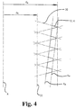
- the external thread 12.4 of the jaw implant 12 has a special shape according to the invention.
- the cross-section of the external thread 12.4 is derived from a fictitious thread, the cross-section of which is an acute-angled triangle 30 which runs helically around a fictitious cylindrical body 32 . 4 , these acute-angled triangles 30 are rotated into the sectional plane or into the plane of the drawing, which is geometrically not entirely correct but very clear.
- the axis of this fictitious cylindrical body 32 coincides with the axis A of the jaw implant 12 and is therefore also marked with A.
- the core diameter of the fictitious thread is denoted by dk and its outside diameter by da .
- the actually existing thread differs from the fictitious thread described above in that the cross section of the actual thread is in each axial position in each case by a certain section from the triangle 30 of the cross section of the fictitious Thread is formed.
- the continuously changing core diameter and the continuously changing outside diameter of the actual thread are determined by two parallel and conical surfaces Kk and Ka here , the opening angle of the corresponding cones being summarized above as the opening angle of the truncated cone surface that forms the implant body 12.2 .
- the conical surface Ka forms the envelope surface on the implant body 12.2, and the conical surface Kk delimits the actual conical implant body 12.2.
- FIG. 5 shows a side view of the jaw implant 12 with the special self-tapping external thread, which was described with reference to FIG. 4 , in a geometrically correct representation. It can be clearly seen that the pitch of the self-tapping external thread 12.4 is selected such that a region of the conical outer surface Kk of the implant body 12.2 is present between adjacent thread turns.
- a jaw implant 12 according to the invention is shown in a side view or in a section perpendicular to the axis A.
- the suspended tapping 12.4 in a plurality of longitudinal regions 40 being shown in Figure 6A, only one of these regions 40..; the longitudinal regions 40 form flutes for the bone chips of the jaw bone 4 that arise during the implantation of the jaw implant 12.
- cutting edges 42 of the self-tapping thread 12.4 are formed at the boundaries of the remaining thread.
- the longitudinal regions 40 shown in FIG. 6A run along the generatrix of the surface of rotation of the implant body 12.4, but could also have the shape of a helix, for example, with a pitch angle that is somewhat larger than the pitch angle of the self-tapping external thread 12.4.
Landscapes
- Health & Medical Sciences (AREA)
- Oral & Maxillofacial Surgery (AREA)
- Orthopedic Medicine & Surgery (AREA)
- Dentistry (AREA)
- Epidemiology (AREA)
- Life Sciences & Earth Sciences (AREA)
- Animal Behavior & Ethology (AREA)
- General Health & Medical Sciences (AREA)
- Public Health (AREA)
- Veterinary Medicine (AREA)
- Dental Prosthetics (AREA)
Priority Applications (2)
| Application Number | Priority Date | Filing Date | Title |
|---|---|---|---|
| EP00119812A EP1186275B1 (fr) | 2000-09-12 | 2000-09-12 | Implant dentaire |
| DE50014816T DE50014816D1 (de) | 2000-09-12 | 2000-09-12 | Kieferimplantat |
Applications Claiming Priority (1)
| Application Number | Priority Date | Filing Date | Title |
|---|---|---|---|
| EP00119812A EP1186275B1 (fr) | 2000-09-12 | 2000-09-12 | Implant dentaire |
Publications (2)
| Publication Number | Publication Date |
|---|---|
| EP1186275A1 true EP1186275A1 (fr) | 2002-03-13 |
| EP1186275B1 EP1186275B1 (fr) | 2007-11-28 |
Family
ID=8169812
Family Applications (1)
| Application Number | Title | Priority Date | Filing Date |
|---|---|---|---|
| EP00119812A Expired - Lifetime EP1186275B1 (fr) | 2000-09-12 | 2000-09-12 | Implant dentaire |
Country Status (2)
| Country | Link |
|---|---|
| EP (1) | EP1186275B1 (fr) |
| DE (1) | DE50014816D1 (fr) |
Cited By (2)
| Publication number | Priority date | Publication date | Assignee | Title |
|---|---|---|---|---|
| US7726969B2 (en) | 2007-05-12 | 2010-06-01 | Walther Gerd Axel | Dental implant, in particular of ceramic material |
| EP3763320A1 (fr) * | 2019-07-08 | 2021-01-13 | Anthogyr | Implant dentaire auto-taraudant ameliore |
Citations (3)
| Publication number | Priority date | Publication date | Assignee | Title |
|---|---|---|---|---|
| US5000686A (en) * | 1990-01-02 | 1991-03-19 | Implant Innovations, Inc. | Dental implant fixture |
| US5556280A (en) * | 1994-05-31 | 1996-09-17 | Pelak; Mark S. | Method and apparatus for appliance mounting |
| WO1999038451A1 (fr) * | 1998-02-03 | 1999-08-05 | Lifecore Biomedical, Inc. | Implant dentaire de type a vis auto-taraudeuse |
Family Cites Families (2)
| Publication number | Priority date | Publication date | Assignee | Title |
|---|---|---|---|---|
| DE3241963C1 (de) * | 1982-11-12 | 1984-04-26 | Feldmühle AG, 4000 Düsseldorf | Schraubenfoermig ausgebildetes Kieferimplantat |
| IT1307923B1 (it) * | 1999-01-25 | 2001-11-29 | Hofmann S A S Di Roberto Hofma | Dispositivo di impianto dentale endosseo. |
-
2000
- 2000-09-12 EP EP00119812A patent/EP1186275B1/fr not_active Expired - Lifetime
- 2000-09-12 DE DE50014816T patent/DE50014816D1/de not_active Expired - Fee Related
Patent Citations (3)
| Publication number | Priority date | Publication date | Assignee | Title |
|---|---|---|---|---|
| US5000686A (en) * | 1990-01-02 | 1991-03-19 | Implant Innovations, Inc. | Dental implant fixture |
| US5556280A (en) * | 1994-05-31 | 1996-09-17 | Pelak; Mark S. | Method and apparatus for appliance mounting |
| WO1999038451A1 (fr) * | 1998-02-03 | 1999-08-05 | Lifecore Biomedical, Inc. | Implant dentaire de type a vis auto-taraudeuse |
Cited By (3)
| Publication number | Priority date | Publication date | Assignee | Title |
|---|---|---|---|---|
| US7726969B2 (en) | 2007-05-12 | 2010-06-01 | Walther Gerd Axel | Dental implant, in particular of ceramic material |
| EP3763320A1 (fr) * | 2019-07-08 | 2021-01-13 | Anthogyr | Implant dentaire auto-taraudant ameliore |
| WO2021005481A1 (fr) * | 2019-07-08 | 2021-01-14 | Anthogyr | Implant dentaire auto-taraudant ameliore |
Also Published As
| Publication number | Publication date |
|---|---|
| EP1186275B1 (fr) | 2007-11-28 |
| DE50014816D1 (de) | 2008-01-10 |
Similar Documents
| Publication | Publication Date | Title |
|---|---|---|
| DE3241963C1 (de) | Schraubenfoermig ausgebildetes Kieferimplantat | |
| EP1100396B1 (fr) | Implant pour maintenir et/ou former une prothese dentaire ou une articulation artificielle du doigt | |
| EP1100395B1 (fr) | Dispositif pour maintenir et/ou former une prothese dentaire | |
| DE69934313T2 (de) | Dentalimplantat | |
| EP1617783B1 (fr) | Implant dentaire | |
| EP1786354B1 (fr) | Systeme d'implant dentaire | |
| DE3421056A1 (de) | Kieferimplantat zur aufnahme eines zahnersatztraegers | |
| WO2006081815A2 (fr) | Implant dentaire | |
| WO2010048944A1 (fr) | Implant dentaire destiné à être inséré dans une mâchoire pour fixer une dent artificielle | |
| DE102006018726A1 (de) | Dentalimplantat und Verfahren zu seiner Herstellung | |
| DE4326841A1 (de) | Implantat-Bausatz | |
| DE19803172C2 (de) | Subgingivales Kieferimplantat | |
| EP1943979B1 (fr) | Implant dentaire | |
| DE10236125B4 (de) | Einschraubbares selbstschneidendes Dentalimplantat | |
| EP1186275B1 (fr) | Implant dentaire | |
| EP1713411B1 (fr) | Implant dentaire | |
| CH693733A5 (de) | Kieferimplantat und Zahnersatz. | |
| WO2014090358A1 (fr) | Système d'implant en une ou plusieurs parties, muni d'un élément de montage présentant une ou plusieurs bagues extérieures | |
| EP0207211B1 (fr) | Moyen de fixation implantable pour prothèses dentaires | |
| EP1205158A1 (fr) | Implant dentaire | |
| DE3828013C2 (fr) | ||
| DE19719451C1 (de) | Zahntechnische Stiftanordnung mit einem überkronbaren Aufbau | |
| DE4035172C2 (fr) | ||
| DE10114627A1 (de) | Implantat | |
| DE102015103288A1 (de) | Implantatsystem und Verfahren zur Einpflanzung eines Dentalimplantats |
Legal Events
| Date | Code | Title | Description |
|---|---|---|---|
| PUAI | Public reference made under article 153(3) epc to a published international application that has entered the european phase |
Free format text: ORIGINAL CODE: 0009012 |
|
| AK | Designated contracting states |
Kind code of ref document: A1 Designated state(s): AT BE CH CY DE DK ES FI FR GB GR IE IT LI LU MC NL PT SE |
|
| AX | Request for extension of the european patent |
Free format text: AL;LT;LV;MK;RO;SI |
|
| 17P | Request for examination filed |
Effective date: 20020503 |
|
| AKX | Designation fees paid |
Free format text: AT BE CH CY DE DK ES FI FR GB GR IE IT LI LU MC NL PT SE |
|
| 17Q | First examination report despatched |
Effective date: 20031024 |
|
| APBN | Date of receipt of notice of appeal recorded |
Free format text: ORIGINAL CODE: EPIDOSNNOA2E |
|
| APBR | Date of receipt of statement of grounds of appeal recorded |
Free format text: ORIGINAL CODE: EPIDOSNNOA3E |
|
| APBK | Appeal reference recorded |
Free format text: ORIGINAL CODE: EPIDOSNREFNE |
|
| APAF | Appeal reference modified |
Free format text: ORIGINAL CODE: EPIDOSCREFNE |
|
| APBT | Appeal procedure closed |
Free format text: ORIGINAL CODE: EPIDOSNNOA9E |
|
| GRAP | Despatch of communication of intention to grant a patent |
Free format text: ORIGINAL CODE: EPIDOSNIGR1 |
|
| RTI1 | Title (correction) |
Free format text: DENTAL IMPLANT |
|
| GRAS | Grant fee paid |
Free format text: ORIGINAL CODE: EPIDOSNIGR3 |
|
| GRAA | (expected) grant |
Free format text: ORIGINAL CODE: 0009210 |
|
| AK | Designated contracting states |
Kind code of ref document: B1 Designated state(s): AT BE CH CY DE DK ES FI FR GB GR IE IT LI LU MC NL PT SE |
|
| REG | Reference to a national code |
Ref country code: IE Ref legal event code: FG4D Free format text: LANGUAGE OF EP DOCUMENT: GERMAN |
|
| REG | Reference to a national code |
Ref country code: CH Ref legal event code: EP |
|
| REF | Corresponds to: |
Ref document number: 50014816 Country of ref document: DE Date of ref document: 20080110 Kind code of ref document: P |
|
| PG25 | Lapsed in a contracting state [announced via postgrant information from national office to epo] |
Ref country code: ES Free format text: LAPSE BECAUSE OF FAILURE TO SUBMIT A TRANSLATION OF THE DESCRIPTION OR TO PAY THE FEE WITHIN THE PRESCRIBED TIME-LIMIT Effective date: 20080311 Ref country code: SE Free format text: LAPSE BECAUSE OF FAILURE TO SUBMIT A TRANSLATION OF THE DESCRIPTION OR TO PAY THE FEE WITHIN THE PRESCRIBED TIME-LIMIT Effective date: 20080228 Ref country code: NL Free format text: LAPSE BECAUSE OF FAILURE TO SUBMIT A TRANSLATION OF THE DESCRIPTION OR TO PAY THE FEE WITHIN THE PRESCRIBED TIME-LIMIT Effective date: 20071128 |
|
| NLV1 | Nl: lapsed or annulled due to failure to fulfill the requirements of art. 29p and 29m of the patents act | ||
| PG25 | Lapsed in a contracting state [announced via postgrant information from national office to epo] |
Ref country code: FI Free format text: LAPSE BECAUSE OF FAILURE TO SUBMIT A TRANSLATION OF THE DESCRIPTION OR TO PAY THE FEE WITHIN THE PRESCRIBED TIME-LIMIT Effective date: 20071128 |
|
| GBV | Gb: ep patent (uk) treated as always having been void in accordance with gb section 77(7)/1977 [no translation filed] | ||
| PG25 | Lapsed in a contracting state [announced via postgrant information from national office to epo] |
Ref country code: DK Free format text: LAPSE BECAUSE OF FAILURE TO SUBMIT A TRANSLATION OF THE DESCRIPTION OR TO PAY THE FEE WITHIN THE PRESCRIBED TIME-LIMIT Effective date: 20071128 |
|
| EN | Fr: translation not filed | ||
| PG25 | Lapsed in a contracting state [announced via postgrant information from national office to epo] |
Ref country code: PT Free format text: LAPSE BECAUSE OF FAILURE TO SUBMIT A TRANSLATION OF THE DESCRIPTION OR TO PAY THE FEE WITHIN THE PRESCRIBED TIME-LIMIT Effective date: 20080428 |
|
| REG | Reference to a national code |
Ref country code: IE Ref legal event code: FD4D |
|
| PLBE | No opposition filed within time limit |
Free format text: ORIGINAL CODE: 0009261 |
|
| STAA | Information on the status of an ep patent application or granted ep patent |
Free format text: STATUS: NO OPPOSITION FILED WITHIN TIME LIMIT |
|
| PG25 | Lapsed in a contracting state [announced via postgrant information from national office to epo] |
Ref country code: FR Free format text: LAPSE BECAUSE OF FAILURE TO SUBMIT A TRANSLATION OF THE DESCRIPTION OR TO PAY THE FEE WITHIN THE PRESCRIBED TIME-LIMIT Effective date: 20080912 Ref country code: IE Free format text: LAPSE BECAUSE OF FAILURE TO SUBMIT A TRANSLATION OF THE DESCRIPTION OR TO PAY THE FEE WITHIN THE PRESCRIBED TIME-LIMIT Effective date: 20071128 |
|
| 26N | No opposition filed |
Effective date: 20080829 |
|
| PG25 | Lapsed in a contracting state [announced via postgrant information from national office to epo] |
Ref country code: GB Free format text: LAPSE BECAUSE OF FAILURE TO SUBMIT A TRANSLATION OF THE DESCRIPTION OR TO PAY THE FEE WITHIN THE PRESCRIBED TIME-LIMIT Effective date: 20071128 |
|
| PG25 | Lapsed in a contracting state [announced via postgrant information from national office to epo] |
Ref country code: GR Free format text: LAPSE BECAUSE OF FAILURE TO SUBMIT A TRANSLATION OF THE DESCRIPTION OR TO PAY THE FEE WITHIN THE PRESCRIBED TIME-LIMIT Effective date: 20080229 |
|
| BERE | Be: lapsed |
Owner name: HERMANN, WERNER Effective date: 20080930 |
|
| PG25 | Lapsed in a contracting state [announced via postgrant information from national office to epo] |
Ref country code: MC Free format text: LAPSE BECAUSE OF NON-PAYMENT OF DUE FEES Effective date: 20080930 |
|
| PGFP | Annual fee paid to national office [announced via postgrant information from national office to epo] |
Ref country code: CH Payment date: 20090318 Year of fee payment: 9 |
|
| PG25 | Lapsed in a contracting state [announced via postgrant information from national office to epo] |
Ref country code: BE Free format text: LAPSE BECAUSE OF NON-PAYMENT OF DUE FEES Effective date: 20080930 Ref country code: CY Free format text: LAPSE BECAUSE OF FAILURE TO SUBMIT A TRANSLATION OF THE DESCRIPTION OR TO PAY THE FEE WITHIN THE PRESCRIBED TIME-LIMIT Effective date: 20071128 |
|
| PG25 | Lapsed in a contracting state [announced via postgrant information from national office to epo] |
Ref country code: DE Free format text: LAPSE BECAUSE OF NON-PAYMENT OF DUE FEES Effective date: 20090401 |
|
| PG25 | Lapsed in a contracting state [announced via postgrant information from national office to epo] |
Ref country code: AT Free format text: LAPSE BECAUSE OF NON-PAYMENT OF DUE FEES Effective date: 20080912 |
|
| REG | Reference to a national code |
Ref country code: CH Ref legal event code: PL |
|
| PG25 | Lapsed in a contracting state [announced via postgrant information from national office to epo] |
Ref country code: LU Free format text: LAPSE BECAUSE OF NON-PAYMENT OF DUE FEES Effective date: 20080912 |
|
| PG25 | Lapsed in a contracting state [announced via postgrant information from national office to epo] |
Ref country code: CH Free format text: LAPSE BECAUSE OF NON-PAYMENT OF DUE FEES Effective date: 20090930 Ref country code: LI Free format text: LAPSE BECAUSE OF NON-PAYMENT OF DUE FEES Effective date: 20090930 |
|
| PG25 | Lapsed in a contracting state [announced via postgrant information from national office to epo] |
Ref country code: IT Free format text: LAPSE BECAUSE OF NON-PAYMENT OF DUE FEES Effective date: 20080930 |