EP1186275A1 - Dental implant and prosthesis - Google Patents
Dental implant and prosthesis Download PDFInfo
- Publication number
- EP1186275A1 EP1186275A1 EP00119812A EP00119812A EP1186275A1 EP 1186275 A1 EP1186275 A1 EP 1186275A1 EP 00119812 A EP00119812 A EP 00119812A EP 00119812 A EP00119812 A EP 00119812A EP 1186275 A1 EP1186275 A1 EP 1186275A1
- Authority
- EP
- European Patent Office
- Prior art keywords
- implant
- jaw
- thread
- external thread
- jaw implant
- Prior art date
- Legal status (The legal status is an assumption and is not a legal conclusion. Google has not performed a legal analysis and makes no representation as to the accuracy of the status listed.)
- Granted
Links
Images


Classifications
-
- A—HUMAN NECESSITIES
- A61—MEDICAL OR VETERINARY SCIENCE; HYGIENE
- A61C—DENTISTRY; APPARATUS OR METHODS FOR ORAL OR DENTAL HYGIENE
- A61C8/00—Means to be fixed to the jaw-bone for consolidating natural teeth or for fixing dental prostheses thereon; Dental implants; Implanting tools
- A61C8/0048—Connecting the upper structure to the implant, e.g. bridging bars
-
- A—HUMAN NECESSITIES
- A61—MEDICAL OR VETERINARY SCIENCE; HYGIENE
- A61C—DENTISTRY; APPARATUS OR METHODS FOR ORAL OR DENTAL HYGIENE
- A61C8/00—Means to be fixed to the jaw-bone for consolidating natural teeth or for fixing dental prostheses thereon; Dental implants; Implanting tools
- A61C8/0018—Means to be fixed to the jaw-bone for consolidating natural teeth or for fixing dental prostheses thereon; Dental implants; Implanting tools characterised by the shape
- A61C8/0022—Self-screwing
-
- A—HUMAN NECESSITIES
- A61—MEDICAL OR VETERINARY SCIENCE; HYGIENE
- A61C—DENTISTRY; APPARATUS OR METHODS FOR ORAL OR DENTAL HYGIENE
- A61C8/00—Means to be fixed to the jaw-bone for consolidating natural teeth or for fixing dental prostheses thereon; Dental implants; Implanting tools
- A61C8/0048—Connecting the upper structure to the implant, e.g. bridging bars
- A61C8/005—Connecting devices for joining an upper structure with an implant member, e.g. spacers
- A61C8/0069—Connecting devices for joining an upper structure with an implant member, e.g. spacers tapered or conical connection
-
- A—HUMAN NECESSITIES
- A61—MEDICAL OR VETERINARY SCIENCE; HYGIENE
- A61C—DENTISTRY; APPARATUS OR METHODS FOR ORAL OR DENTAL HYGIENE
- A61C8/00—Means to be fixed to the jaw-bone for consolidating natural teeth or for fixing dental prostheses thereon; Dental implants; Implanting tools
- A61C8/0048—Connecting the upper structure to the implant, e.g. bridging bars
- A61C8/005—Connecting devices for joining an upper structure with an implant member, e.g. spacers
- A61C8/0068—Connecting devices for joining an upper structure with an implant member, e.g. spacers with an additional screw
Landscapes
- Health & Medical Sciences (AREA)
- Oral & Maxillofacial Surgery (AREA)
- Orthopedic Medicine & Surgery (AREA)
- Dentistry (AREA)
- Epidemiology (AREA)
- Life Sciences & Earth Sciences (AREA)
- Animal Behavior & Ethology (AREA)
- General Health & Medical Sciences (AREA)
- Public Health (AREA)
- Veterinary Medicine (AREA)
- Dental Prosthetics (AREA)
Abstract
Description
Gegenstand der Erfindung ist ein Kieferimplantat für einen Zahnersatz nach dem Oberbegriff
des Anspruchs 1 sowie ein Zahnersatz nach dem Oberbegriff des Anspruchs 11. The invention relates to a jaw implant for a denture according to the preamble of claim 1 and a denture according to the preamble of
Natürliche Zähne erfahren im Laufe der Zeit verschiedenste Beeinträchtigungen, beispielsweise wegen mangelhafter Mundhygiene, altersgemässer Abnutzung oder durch Unfälle. Diese Beeinträchtigungen manifestieren sich als Beschädigungen von Zahnbereichen einzelner Zähne oder als Fehlen ganzer Zähne und Zahngruppen. Herkömmlicherweise werden fehlende Bereiche von Zähnen durch Onlays, Inlays oder Kronen ersetzt, und fehlende Zähne oder Zahngruppen werden entweder durch Brücken oder durch Prothesen ersetzt. Onlays, Inlays und Kronen werden fest am noch vorhandenem Restzahn fixiert, während Brükken fest an den den fehlenden Zähnen und Zahngruppen benachbarten, noch vorhandenen Zähnen montiert werden. Prothesen sind für die tägliche Reinigung und für die Nachtruhe entfernbar und werden entweder an noch vorhandenem echtem Zahnmaterial befestigt oder sind so ausgebildet, dass sie sich durch ihre Formgebung am Kiefer und am Gaumen abstützen.Natural teeth experience various impairments over time, for example due to poor oral hygiene, age-related wear and tear or accidents. These impairments manifest themselves as damage to individual tooth areas Teeth or as the absence of whole teeth and groups of teeth. Conventionally missing areas of teeth replaced by onlays, inlays or crowns, and missing teeth or tooth groups are replaced either by bridges or by prostheses. onlays, Inlays and crowns are firmly attached to the remaining tooth while bridges firmly attached to the still existing adjacent to the missing teeth and groups of teeth Teeth are mounted. Prostheses are for daily cleaning and for rest at night removable and are either attached to still existing dental material or are designed so that they are supported on the jaw and palate by their shape.
Das oben beschriebene Vorgehen zum Ersetzen fehlender Zahnbereiche und Zähne hat zahlreiche Nachteile, die im folgenden beschrieben werden.The procedure described above for replacing missing tooth areas and teeth has numerous disadvantages, which are described below.
Ein gravierender Nachteil ist in der Notwendigkeit zu sehen, noch vorhandenes und im allgemeinen gesundes Zahnmaterial zu opfern. Der Bereich, an welchem ein Zahnersatzteil zu montieren ist, muss vorgängig präpariert werden. Zu diesem Zweck ist es jeweils erforderlich, Zahnmaterial des zu ergänzenden Restzahnes oder der benachbarten Zähne von zu ersetzenden Zähnen oder Zahngruppen abzuschleifen. Da einmal entferntes Zahnmaterial vom Körper nicht nachgebildet wird, ist jedes Abtragen von noch gesundem Zahnmaterial natürlich unerwünscht und sollte möglichst vermieden werden, insbesondere im Hinblick auf weitere Zahnreparaturen im gleichen Kieferbereich, die meist nach einiger Zeit notwendig werden, weil die Zahnersatzteile einem gewissen Verschleiss unterliegen, und die das Abschleifen von weiterem Zahnmaterial nötig machen.A serious disadvantage is the need to see what still exists and in general sacrifice healthy dental material. The area where a dental prosthesis is too must be prepared beforehand. For this purpose, it is necessary Tooth material of the rest of the tooth to be supplemented or of the adjacent teeth grinding replacement teeth or groups of teeth. Once tooth material is removed is not reproduced by the body, every removal of healthy tooth material of course undesirable and should be avoided if possible, especially with regard to further tooth repairs in the same jaw area, which are usually necessary after some time because the tooth replacement parts are subject to a certain amount of wear, of additional tooth material.
Ein weiterer Nachteil der herkömmlich durchgeführten Gebissreparaturen betrifft insbesondere den Ersatz ganzer Zähne und Zahngruppen. Ein Ersatz durch eine Brücke ist häufig nicht sehr dauerhaft und in vielen Fällen auch optisch unbefriedigend, während ein Ersatz durch eine Prothese vor allem wegen mangelndem Tragkomfort und einer Beeinträchtigung der Lebensqualität unerwünscht ist.Another disadvantage of the conventional denture repairs concerns in particular the replacement of entire teeth and groups of teeth. Replacement with a bridge is common not very permanent and in many cases also optically unsatisfactory while a replacement due to a prosthesis mainly because of poor comfort and impairment the quality of life is undesirable.
Die oben beschriebenen herkömmlichen Verfahren zum Ersetzen von beschädigten oder fehlenden Zahnbereichen oder Zähnen beruhen auf dem Prinzip, nur diejenigen fehlenden Partien von Zähnen oder Zahngruppen zu ersetzen, die sichtbar sind bzw. die über das Zahnfleisch hinaus in die Mundhöhle ragen.The conventional methods described above for replacing damaged or missing tooth areas or teeth are based on the principle, only those missing To replace lots of teeth or groups of teeth that are visible or that over the Protrude gums into the oral cavity.
Infolge der erwähnten Nachteile dieser herkömmlichen Verfahren wird seit einiger Zeit versucht, Gebissreparaturen mit Zahnersatz durchzuführen, dessen sichtbare Bereiche sich nicht auf Restzahnbereiche oder Restzähne sondern auf Kieferimplantate abstützen. Ein solcher Zahnersatz ersetzt also einen gesamten Zahn, wobei die Kieferimplantate gewissermassen die Funktion der Zahnwurzel übernehmen. Gegenüber der natürlichen Gebissanlage besteht aber diesbezüglich ein wesentlicher Unterschied. In der natürlichen Gebissanlage besteht aber ein wesentlicher Unterschied. Im natürlichen Gebiss besitzt bekanntlich jeder Zahn seine eigene Zahnwurzel, und entsprechend ist zur Abstützung eines einzelnen Zahnersatzteiles auch stets eine Ersatzzahnwurzel in Form eines Kieferimplantates notwendig. Sind aber Zahngruppen von zwei und mehr benachbarten Zähnen zu ersetzen, so muss nicht jeder zu ersetzende Zahn eine eigene Ersatzzahnwurzel erhalten; es muss also nicht an jeder Stelle eines zu ersetzenden Zahnes ein Kieferimplantat vorgesehen werden, sondern es reichen im allgemeinen zwei Kieferimplantate, um den Ersatz mehrerer mehrerer Zähne zu befestigen; je nach den Verhältnissen reicht sogar ein einziges Kieferimplantat aus, um den Ersatz zweier benachbarter Zähne zu befestigen.Due to the mentioned disadvantages of these conventional methods, attempts have been made for some time to Denture repairs to be carried out with visible dentures Do not rest on residual tooth areas or residual teeth but on jaw implants. On such dentures thus replace an entire tooth, the jaw implants to a certain extent take over the function of the tooth root. Opposite the natural bit system but there is a significant difference in this regard. In the natural bite system but there is an essential difference. As is well known, in natural teeth each tooth has its own tooth root, and is appropriate for supporting an individual Dental prosthesis also always has a replacement tooth root in the form of a jaw implant necessary. However, if tooth groups of two or more adjacent teeth have to be replaced, this means that not every tooth to be replaced has its own replacement tooth root; it must a jaw implant cannot therefore be provided at every point of a tooth to be replaced, two jaw implants are generally sufficient to replace several attach multiple teeth; depending on the circumstances, even a single jaw implant is sufficient to secure the replacement of two adjacent teeth.
Ein bedeutender Vorteil von Zahnersatz mit Implantatbasis ist darin zu sehen, dass sich, vorausgesetzt der Kieferknochen bleibe gesund, die Fixierung des Kieferimplantates mit fortlaufender Zeit verbessert, während andere Zahnersatzteile wie Inlays, Onlays, Kronen und Brücken die Neigung haben, sich im Laufe der Zeit zu lockern.A significant advantage of dentures with an implant base can be seen in the fact that provided the jaw bone remains healthy, the fixation of the jaw implant with Continuous improvement while other dentures such as inlays, onlays, crowns and bridges tend to loosen over time.
Zahnersatz, der mit Hilfe von Kieferimplantaten hergestellt ist, umfasst mehrere Bestandteile, die nicht alle gleichzeitig bzw. an einem Stück in der Mundhöhle des Patienten montiert werden. Grundsätzlich ist es von Vorteil, den Zahnersatz so zu konzipieren, dass die definitiv implantierten und somit nicht mehr ersetzbaren Bestandteile in ihrer minimalsten Form ausgebildet bzw. auf den eigentlichen Implantatbereich beschränkt sind.Dentures made with the help of jaw implants consist of several components, which are not all assembled at the same time or in one piece in the patient's oral cavity become. Basically, it is advantageous to design the dentures so that they definitely implanted and therefore no longer replaceable components in their minimal form or are limited to the actual implant area.
Im allgemeinen umfasst ein Zahnersatz ein Kieferimplantat und eine Suprakonstruktion. Das Kieferimplantat wird als erstes definitiv im Kieferknochen des Patienten angebracht wird, wo es im Laufe der Zeit einwächst oder, besser gesagt, von sich bildender Kochensubstanz umwachsen wird. Auf diesem Kieferimplantat wird dann als zweites die Suprakonstruktion des Zahnersatzes befestigt; die Suprakonstruktion umfasst mindestens den sichtbaren bzw. über das Zahnfleisch hinausragenden Teil des Zahnersatzes. Kieferimplantat und Suprakonstruktion müssen miteinander verbunden werden, wozu ein Verbindungskörper benutzt wird, der entweder mit dem Kieferimplantat oder mit der Suprakonstruktion integral ist oder der ein selbständiges Teil bildet.Generally, a denture includes a jaw implant and a superstructure. The Jaw implant is the first thing that is definitely placed in the patient's jawbone where it grows over time or, better said, cooking substance that forms will grow over. The second is the superstructure on this jaw implant the dentures attached; the superstructure includes at least the visible or part of the denture protruding beyond the gums. Jaw implant and superstructure must be connected to each other using a connector body which is either integral with the jaw implant or with the superstructure or the one forms an independent part.
Die Suprakonstruktion kann aus einem oder mehreren Elementen bestehen; gebräuchlich sind Suprakonstruktionen aus drei Elementen, nämlich erstens einem Verbindungskörper, zweitens einem Gerüst und drittens einer Verblendung, wobei Gerüst und Verblendung auch als Kappe bezeichnet werden. Der Verbindungskörper ist im fertigen Zustand nicht sichtbar; er wird wie schon erwähnt am Kieferimplantat befestigt, wobei für jedes Kieferimplantat ein Verbindungskörper vorgesehen ist. Das Gerüst ist mit einem oder mehreren Verbindungskörpern verbunden und bildet die Struktur des in die Mundhöhle ragenden Teils des Zahnersatzes. Die Verblendung ummantelt das Gerüst und bildet den einzigen tatsächlich sichtbaren Teil des Zahnersatzes; eine Verblendung gehört zu einem Gerüst und kann zu einem oder mehreren Verbindungskörpern und entsprechend zu einem oder mehreren Kieferimplantaten gehören. Bei Verwendung eines geeigneten Werkstoffes können das Gerüst und die Verblendung auch integral gefertigt sein.The superstructure can consist of one or more elements; common are superstructures made up of three elements, namely firstly a connecting body, secondly a scaffold and thirdly a veneer, with the framework and veneer also be called a cap. The connector body is not visible in the finished state; As already mentioned, it is attached to the jaw implant, with one for each jaw implant Connection body is provided. The scaffold is with one or more connecting bodies connected and forms the structure of the part of the denture protruding into the oral cavity. The veneer covers the scaffolding and forms the only one that is actually visible Part of dentures; a veneer belongs to a scaffolding and can belong to one or more connecting bodies and corresponding to one or more jaw implants belong. When using a suitable material, the scaffold and the veneer can also be made integrally.
Das Kieferimplantat bildet somit den prostalsten Teil und die Verblendung den distalsten Teil des Zahnersatzes.The jaw implant thus forms the most prostal part and the veneer the most distal part of the dentures.
Die Verwendung dieser Vielzahl von konstruktiven Elementen zur Erzeugung eines Zahnersatzes bedingt, dass die gegenseitigen Befestigungen von Kieferknochen und Kieferimplantat, von Kieferimplantat und Verbindungskörper, von Verbindungskörper und Gerüst sowie von Gerüst und Verblendung bezüglich Geometrie, Festigkeit und Alterungsbeständigkeit einwandfrei ausgeführt werden. Besonderes sorgfältig muss die Befestigung des Kieferimplantates im Kieferknochen durchgeführt werden; beim Setzen des Kieferimplantates wird ja notwendigerweise die Substanz des Kieferknochens angegriffen; eine Korrektur eines beim Setzen des Kieferimplantates unterlaufenen Fehlers ist daher nicht in jedem Fall möglich und stets schwierig, zeitraubend und schmerzhaft.The use of this multitude of constructive elements for the production of a denture requires that the mutual fixation of jawbone and jaw implant, of jaw implant and connecting body, of connecting body and framework and of framework and veneer with regard to geometry, strength and aging resistance be executed properly. The attachment of the jaw implant must be carried out with particular care be carried out in the jawbone; when placing the jaw implant, yes necessarily attacked the substance of the jawbone; a correction of a It is therefore not always possible to place the mistake made in the jaw implant and always difficult, time consuming and painful.
Kieferimplantate können entweder in den Kieferknochen eingepflockt oder im Kieferknochen eingeschraubt werden, wobei das letztere Verfahren bevorzugt und häufiger durchgeführt wird, da die Gefahr einer lokalen Kieferzertrümmerung beim Einpflocken sehr gross ist. Bekannte Kieferimplantate, die eingeschraubt werden, weisen im allgemeinen über einen bedeutenden Teil ihrer Länge ein Aussengewinde auf und sind meist von ihrem am Patienten distal zu liegen kommenden Ende bis zu ihrem am Patienten proximal zu liegen kommenden Ende zulaufend ausgebildet. Sie haben unter anderem den Nachteil, dass das Schneiden von Gewinden im Kieferknochen und das Einschrauben des Kieferimplantates in das geschnittene Knochen-Muttergewinde nicht einfach durchzuführende Vorgänge sind, und dass die Kieferimplantate jeweils bis zu einer bestimmten Tiefe eingeschraubt werden müssen, damit sie tatsächlich fest und dauerhaft im Kieferknochen fixiert sind. Jaw implants can either be implanted in the jawbone or in the jawbone are screwed in, the latter method being preferred and carried out more frequently because there is a very high risk of local jaw destruction when pegging. Known Jaw implants that are screwed in generally have a significant one Part of their length has an external thread and are mostly of theirs on the patient the distal end to the proximal end of the patient End tapered. Among other things, they have the disadvantage that cutting of threads in the jawbone and screwing the jaw implant into the cut Bone nut threads are not easy to do, and that the jaw implants must be screwed in to a certain depth, so that they are actually firmly and permanently fixed in the jawbone.
Die Aufgabe der Erfindung wird nun darin gesehen,
- ein Kieferimplantat der eingangs genannten Art zu schaffen, welches so ausgebildet ist, dass es sich in einfaacher Weise und kieferknochenschonend einschrauben lässt und welches im implantierten Zustand einwandfrei fixiert ist, ohne dass eine bestimmte Einschraubtiefe genau eingehalten werden muss, und
- einen Zahnersatz mit dem neuen Kieferimplantat vorzuschlagen, bei welchem die Suprakonstruktion so ausgebildet ist, dass der Zahnersatz sowohl bezüglich Ästhetik wie bezüglich Mundhygiene gegenüber dem Stand der Technik verbessert ist.
- to create a jaw implant of the type mentioned, which is designed so that it can be screwed in in a simple manner and is gentle on the jawbone, and which is properly fixed in the implanted state without a specific screw-in depth having to be observed exactly, and
- to propose a denture with the new jaw implant, in which the superstructure is designed in such a way that the denture is improved over the prior art in terms of both aesthetics and oral hygiene.
Die Lösung dieser Aufgabe erfolgt
- für das Kieferimplantat durch die Merkmale des kennzeichnenden Teils des Anspruchs 1, und
- für den Zahnersatz durch die Merkmale des kennzeichnenden Teils des
Anspruchs 11.
- for the jaw implant by the features of the characterizing part of claim 1 , and
- for dentures by the features of the characterizing part of
claim 11.
Vorteilhafte Weiterbildungen des neuen Kieferimplantates und des neuen Zahnersatzes
werden durch die abhängigen Ansprüche 2 bis 10 bzw. 12 bis 20 definiert.Advantageous further developments of the new jaw implant and the new denture are defined by the
Das neue Kieferimplantat lässt sich dank seinem speziell ausgebildeten selbstschneidenden Aussengewinde verhältnismässig leicht implantieren, das heisst in den Kieferknochen einschrauben, wobei praktisch keine Gefahr besteht, dass der Kieferknochen beschädigt bzw. aufgesprengt wird. Da das Aussengewinde selbstschneidend ist, muss im Kieferknochen vorgängig kein Gewinde geschnitten sondern lediglich eine dem Kernkörper des Implantates entsprechende Bohrung erzeugt werden. Dies erleichtert die Arbeit des Dentisten beträchtlich, nicht nur, weil die Erzeugung einer Bohrung weit einfacher ist als das Schneiden eines Gewindes, sondern auch, weil die Implantierung in eine Bohrung viel einfacher ist als das Einschrauben in ein vorgängig erzeugtes Gewinde. Durch das neue Gewinde erfolgt in jedem Falle eine solide Fixierung des Kieferimplantates; wobei es nicht erforderlich ist, dass das Implantat eine genau vorgegebene Rotations-Winkellage einnimmt bzw. dass eine genau vorbestimmte Einschraubtiefe eingehalten wird. Dies trägt weiter dazu bei, den Vorgang der Implantierung des Kieferimplantates zu vereinfachen. Der Vorteil der einfachen Implantierung ist noch ausgeprägter, wenn ein Zahnersatz, natürlich nur für einen einzelnen Zahn, hergestellt wird, bei welchem Kieferimplantat und Suprakonstruktion, ggfs. ohne Verblendung, integral hergestellt sind und zusammen im Kiefer eines Patienten angeordnet werden; der Kieferimplantat-Bereich eines solchen integralen Zahnersatzes kann dann einfach soweit in den Kieferknochen eingeschraubt werden, bis der Suprakonstruktions-Abschnitt des Zahnersatzes seine richtige Rotations-Winkellage und seine richtige axiale Lage gefunden hat.The new jaw implant can be thanks to its specially trained self-tapping Implant the external thread relatively easily, i.e. screw it into the jawbone, there is practically no risk that the jawbone will be damaged or is blown up. Since the external thread is self-tapping, it must be in the jawbone No thread previously cut, but only one of the core body of the implant corresponding hole will be created. This greatly facilitates the dentist’s work, not just because drilling a hole is far easier than cutting one Thread, but also because implanting it in a hole is much easier than that Screwing into a previously created thread. Thanks to the new thread, everyone can Case a solid fixation of the jaw implant; it is not necessary that the implant assumes a precisely specified rotational angular position or that an exactly predetermined screw-in depth is observed. This further contributes to the process to simplify the implantation of the jaw implant. The advantage of simple implantation is even more pronounced if a denture, of course only for a single tooth, is produced, in which jaw implant and superstructure, possibly without veneer, are integrally made and placed together in a patient's jaw; the jaw implant area of such an integral denture can then simply go so far to be screwed into the jawbone until the superstructural section of the Found the correct rotational angular position and its correct axial position Has.
Das erfindungsgemässe Kieferimplantat unterscheidet sich vor allem durch die Formgebung seines Aussengewindes von herkömmlichen einschraubbaren Kieferimplantaten. Das neue Aussengewinde ist so ausgebildet, dass sich der Gewindequerschnitt längs des Gewindes laufend und kontinuierlich ändert. Im proximalen Bereich, wo der Durchmesser des konischen, mittleren Teils des Kieferimplantates, der auch als Implantatkörper bezeichnet wird, gering ist, hat der Gewindequerschnitt etwa die Form eines Trapezes mit breiter Grundlinie; im distalen Bereich des Implantatkörpers hat der Gewindequerschnitt die Form Trapezes mit schmaler Grundlinie oder im Extremalfall die Form eines spitzwinkligen Dreiecks; die dazwischenliegenden Gewindequerschnitte bilden bezüglich ihrer Form einen übergang vom proximalen, breiten trapezartigen Gewindequerschnitt zum distalen, schmalen, spitzwinkligen, dreieckförmigen Gewindequerschnitt. Alle Gewindequerschnitte beruhen auf demselben fiktiven spitzwinkligen Dreieck, welches sich schraubenlinienartig um einen fiktiven zylindrischen Körper windet, dessen Rotationsachse mit der Längsachse des Kieferimplantates zusammenfällt. Durch zwei Rotationsflächen, deren Rotationsachsen ebenfalls mit der Längsachse des Kieferimplantates zusammenfallen, werden dann die tatsächlichen Gewindequerschnitte begrenzt, wobei die innere Rotationsfläche den Gewindekern bzw. den jeweiligen örtlichen Kerndurchmesser bildet, während die äussere Rotationsfläche nur fiktiv ist und den jeweiligen örtlichen Aussendurchmesser des Gewindequerschnittes bestimmt bzw. eine Hüllfläche an das selbstschneidende Aussengewinde bildet. Vorzugsweise handelt es sich bei diesen Rotationsflächen um Kegelstumpfflächen, die parallel oder nicht parallel verlaufen können. Die tatsächlichen Gewindequerschnitte sind also Ausschnitte aus dem beschriebenen fiktiven Dreieck, wobei es sich im proximalen Bereiche um Ausschnitte aus dem Grundlinienbereich und im distalen Bereich um Ausschnitte aus dem Spitzenbereich des fiktiven Dreiecks handelt; hierbei ist es nicht notwendig, dass der distalste Bereich tatsächlich die nach Aussen ragende Spitze des fiktiven Dreiecks umfasst. Trotz seiner verhältnismässig komplizierten Formgebung lässt sich das Kieferimplantat nach der Erfindung bzw. sein Gewinde verhältnismässig einfach auf geeigneten programmierbaren Maschinen herstellen, da es eine geometrisch eindeutig definierbare Form aufweist.The jaw implant according to the invention differs primarily in the shape its external thread from conventional screw-in jaw implants. The new External thread is designed so that the thread cross section along the thread changes continuously and continuously. In the proximal area, where the diameter of the conical, middle part of the jaw implant, which is also referred to as the implant body, is small, the thread cross-section has approximately the shape of a trapezoid with a broad base line; in the distal area of the implant body, the thread cross section has the shape of a trapezoid narrow baseline or, in extreme cases, the shape of an acute-angled triangle; the in between Thread cross sections form a transition from the proximal, wide trapezoidal thread cross-section for distal, narrow, acute-angled, triangular thread cross section. All thread cross sections are based on the same fictitious acute-angled triangle, which is like a helix around a fictitious cylindrical Body twists, its axis of rotation with the longitudinal axis of the jaw implant coincides. Through two surfaces of rotation, whose axes of rotation also with the The actual thread cross-sections then become the longitudinal axis of the jaw implant limited, the inner surface of rotation of the thread core or the respective local core diameter, while the outer surface of rotation is only fictitious and the respective local outside diameter of the thread cross section is determined or forms an enveloping surface on the self-tapping external thread. It is preferably these rotating surfaces are frustoconical surfaces that run parallel or not parallel can. The actual thread cross-sections are therefore excerpts from the one described fictional triangle, with cutouts from the proximal area Baseline area and in the distal area around sections from the tip area of the fictional triangle; it is not necessary that the most distal area actually encompasses the outwardly protruding tip of the fictitious triangle. Despite its proportionate complicated shape, the jaw implant according to the invention or make its thread relatively easily on suitable programmable machines, because it has a geometrically clearly definable shape.
Vorteilhafterweise wird die Steigung des Gewindes, natürlich in Relation zum Gewindequerschnitt, so gewählt, dass zwischen zwei benachbarten Gewindegängen stets ein Abschnitt der Rotationsfläche vorhanden ist. Dadurch verbessert sich die Anlage des Kieferimplantates im Kieferknochen.Advantageously, the pitch of the thread, of course in relation to the thread cross section, chosen so that there is always a section between two adjacent threads the surface of rotation is present. This improves the placement of the jaw implant in the jawbone.
Der Winkel des fiktiven Dreiecks, das die Basis für die Gewindequerschnitte liefert, und der am distalen Ende des Implantatkörpers den tatsächlichen Spitzenwinkel des dortigen Gewindeqürschnittes bildet, ist nach unten nahezu unbegrenzt; er kann minimal sein und bei weniger als 1° liegen; er kann aber auch grösser sein und liegt maximal im Bereich von etwa 40°. Ist der Implantatkörper stark zulaufend ausgebildet, so sind eher spitzere Winkel zu wählen als in Fällen, in denen der Implantatkörper eher zylinderförmig ist.The angle of the fictitious triangle, which provides the basis for the thread cross sections, and the at the distal end of the implant body the actual tip angle of the thread cross-section there forms, is almost unlimited downwards; it can be minimal and at are less than 1 °; however, it can also be larger and is at most in the range of approximately 40 °. If the implant body is made tapering, then the angles are more acute choose than in cases where the implant body is more cylindrical.
Das fiktive Dreieck, welches als Basis für die Gewindequerschnitte angesehen werden kann, muss nicht gleichschenklig sein; die sich gegenüberliegenden Flanken des Gewindequerschnittes eines Gewindeganges können also gegenüber der kegelstumpfförmigen Rotationsfläche des Implantatkörpers unterschiedliche Neigungen aufweisen. Auf diese Weise erhält man ein Gewinde mit einer sägezahnartigen Kontur.The fictitious triangle, which can be used as the basis for the thread cross-sections, does not have to be isosceles; the opposite flanks of the thread cross section a thread can therefore face the frustoconical surface of revolution of the implant body have different inclinations. In this way you get a thread with a sawtooth-like contour.
Um eine Art Schneiden am Aussengewinde und eine Nut für die anfallenden Knochenspäne zu bilden, können die Gewindegänge durch Ausnehmungen unterbrochen sein. Diese Ausnehmungen können sich längs einer Erzeugenden der Rotationsfläche oder längs einer steilen Schraubenlinie an der Rotationsfläche erstrecken. Die so entstehenden Schneidkanten können derart bearbeitet werden, dass ein Freiwinkel entsteht.A kind of cutting on the external thread and a groove for the bone chips to form, the threads can be interrupted by recesses. These recesses can be along a generatrix of the surface of revolution or along one extend steep helix on the surface of revolution. The resulting cutting edges can be edited in such a way that a clearance angle is created.
Der distale Teil des Kieferimplantates ist vorzugsweise aussen konisch ausgebildet. Dadurch erreicht man einen dichtenden Sitz des Kieferimplantates im Kieferknochen und vermeidet den Eintritt von entzündungsauslösenden Verschmutzungen in den Raum zwischen Zahnfleisch und Kieferknochen einerseits und Kieferimplantat anderseits.The distal part of the jaw implant is preferably conical on the outside. Thereby one achieves a tight fit of the jaw implant in the jaw bone and avoids it the entry of inflammation-causing contamination into the space between the gums and jaw bone on the one hand and jaw implant on the other.
Der erfindungsgemässe Zahnersatz ist so ausgebildet, dass sowohl eine problemlose Implantierung des Kieferimplantates im Kieferknochen als auch eine einwandfreie gegenseitige Lage und Befestigung von Kieferimplantat und Suprakonstruktion realisiert werden kann. Dazu dienen die besondere Ausbildung des selbstschneidenden Gewindes und die konische und somit dichtende Formgebung des Kopfes des Kieferimplantates in Kombination mit der Ausbildung der zur gegenseitigen Anlage kommendenden Bereiche des Kieferimplantates und der Suprakonstruktion. The dental prosthesis according to the invention is designed so that both a problem-free implantation of the jaw implant in the jaw bone as well as a flawless mutual Location and attachment of jaw implant and superstructure can be realized. The special design of the self-tapping thread and the tapered serve this purpose and thus sealing shape of the head of the jaw implant in combination with the Training of the areas of the jaw implant coming into mutual contact and the superstructure.
Ein zusätzlicher Vorteil des neuen Zahnersatzes ist darin zu sehen, dass das Kieferimplantat einen verhältnismässig kleinen und die Suprakonstruktion einen verhältnismässig grossen Anteil des Zahnersatzes darstellt. Grundsätzlich sollte nämlich der Anteil des Kieferimplantates zwar so gross wie nötig aber auch so klein wie möglich sein, oder, mit anderen Worten, die Schnittstelle zwischen Kieferimplantat und Suprakonstruktion sollte so distal wie nötig aber so prostal wie möglich liegen. Der Grund dafür ist, dass zwar die Suprakonstruktion relativ leicht ausgetauscht bzw. ersetzt werden kann, dass aber eine Ersetzen des Kieferimplantates möglichst nicht nötig sein sollte, und dass es natürlich vorteilhaft ist, den Zahnersatz so zu gestalten, dass die ersetzbaren Bestandteile möglichst weitreichend ausgebildet sind. Für die gegenseitige Verbindung von Kieferimplantat und Suprakonstruktion wird meist an einem der Teile ein Vorsprung und am anderen der Teile eine Ausnehmung zur Aufnahme des Vorprunges vorgesehen, wobei es in Übereinstimmungen mit den obigen Darlegungen natürlich vorteilhafter ist, den Vorsprung an der Suprakonstruktion und die Ausnehmung am Kieferimplantat auszubilden.An additional advantage of the new dentures is that the jaw implant a relatively small and the superstructure a relatively large Represents dentures. Basically, the proportion of the jaw implant should be as big as necessary but also as small as possible, or, in other words, the interface between the jaw implant and the superstructure should be as distal as necessary but lie as prostally as possible. The reason for this is that although the superstructure can be replaced or replaced relatively easily, but that a replacement of the jaw implant should not be necessary if possible, and that it is of course advantageous, the dentures to be designed in such a way that the replaceable components are designed to be as extensive as possible are. For the mutual connection of jaw implant and superstructure is mostly a projection on one of the parts and a recess for receiving on the other of the parts of the projection provided, in accordance with the above statements is of course more advantageous, the projection on the superstructure and the recess to train on the jaw implant.
Beim neuen Zahnersatz umfassen die Mittel zur gegenseitigen Befestigung von Kieferimplantat und Suprakonstruktion ein Gewinde am Kieferimplantat und ein komplementäres Gewinde an einem Verbindungskörper der Suprakonstruktion, wobei es natürlich vorteilhaft ist, das Gewinde des Kieferimplantates als Innengewinde und demzufolge das Gewinde des Verbindungskörpers als ein Aussengewinde auszubilden.With the new dentures, the means for mutual attachment of jaw implants include and superstructure a thread on the jaw implant and a complementary one Thread on a connecting body of the superstructure, whereby it is of course advantageous is the thread of the jaw implant as an internal thread and therefore the thread of the Form connecting body as an external thread.
Das Verschrauben von Kieferimplantat und Verbindungskörper kann erleichtert werden durch zwei sich im verschraubten Zustand berührende gegensinnig zulaufende Flächen, das heisst eine Fläche am Kieferimplantat und eine komplementäre Fläche am Verbindungskörper. Durch die zulaufenden Flächen erhält man aber vor allem eine dichtende gegenseitige Anlage von Verbindungskörper und Kieferimplantat, so dass keine Verunreinigungen in den von Verbindungskörper und Kieferimplantat begrenzten Raum eindringen , sich dort ablagern und damit zu entzündungsverursachenden Herden werden können.The screwing of the jaw implant and connecting body can be facilitated by two oppositely tapering surfaces touching when screwed together, the means a surface on the jaw implant and a complementary surface on the connecting body. Due to the tapering surfaces, one obtains above all a sealing mutual Attachment of connecting body and jaw implant so that no contamination in the penetrate the space delimited by the connecting body and the jaw implant, deposit there and can thus become inflammation-causing foci.
Die Suprakonstruktion umfasst den bereits erwähnten Verbindungskörper sowie eine Kappe, welche im wesentlichen den sichtbaren Teil des Zahnersatzes bildet.The superstructure includes the connection body already mentioned and a cap, which essentially forms the visible part of the denture.
Verbindungskörper und Kappe können integral hergestellt sein, bestehen aber im allgemeinen aus zwei aneinander befestigten Teilen. Um eine dichtende Verbindung von Verbindungskörper und Kappe zu erhalten und deren gegenseitige Befestigung zu erleichtern, ist es günstig, am Verbindungskörper eine Positionierfläche und an der Kappe eine Komplementärfläche vorzusehen, die sich im verbundenen Zustand berühren. Diese Flächen sind vorzugsweise gegenläufig zulaufend ausgebildet.The connector body and cap can be made integrally, but generally exist from two parts fastened together. For a sealing connection of the connector body and cap and to facilitate their mutual attachment is it favorable, a positioning surface on the connecting body and a complementary surface on the cap to provide that touch when connected. These areas are preferably designed to run in opposite directions.
Besonders günstig ist es, wenn die Positionierfläche und/oder die Komplementärfläche eine Ausnehmung aufweisen, derart, dass im zusammengefügten Zustand ein Hohlraum entsteht, der durch die Positionierfläche und die Komplementärfläche begrenzt ist. Dieser Hohlraum dient zur Aufnahme von Zement oder Klebstoff, mit deren Hilfe die Kappe am Verbindungskörper befestigt wird. Die Verbindung von Kappe und Verbindungskörper kann auch mittels einer quer zur Längsachse des Zahnersatzes einschraubbaren Schraube, die vorne in diesen Hohlraum reicht, realisiert werden. Eine weitere Variante der Verbindung von Kappe und Verbindungskörper ist die thermische Herstellung eines Pressitzes.It is particularly favorable if the positioning surface and / or the complementary surface is one Have recess, such that a cavity is formed in the assembled state, which is limited by the positioning surface and the complementary surface. This cavity is used to hold cement or glue, with the help of which the cap on the connecting body is attached. The connection between cap and connecting body can also by means of a screw that can be screwed in transversely to the longitudinal axis of the denture, the front into this cavity, can be realized. Another variant of the connection of the cap and connecting body is the thermal production of a press fit.
Im allgemeinen ist die Kappe aus zwei Bestandteilen aufgebaut, nämlich aus einem Gerüst und einer Verblendung, die das Gerüst ummantelt.In general, the cap is made up of two components, namely a framework and a veneer that encases the scaffold.
Ein Zahnersatz weist ein einzelnes oder zwei Kieferimplantate und eine entsprechende Suprakonstruktion auf und bildet einen Ersatz für einen oder mehrere fehlende benachbarte ursprüngliche Zähne.A denture has a single or two jaw implants and a corresponding superstructure and forms a replacement for one or more missing neighboring ones original teeth.
Weitere Vorteile und bevorzugte Ausführungsbeispiele der Erfindung werden im folgenden anhand von Ausführungsbeispielen und mit Bezug auf die Zeichnung, die einen integralen Teil der Offenbarung darstellt, ausführlich beschrieben. Es zeigen:
- Fig. 1
- einen Unterkiefer mit einem Zahnersatz einschliesslich eines Kieferimplantates nach der Erfindung, ausschnittweise und vereinfacht, in einem Schaubild;
- Fig. 2A
- einen Unterkiefer mit einem ersten Zahnersatz einschliesslich eines Kieferimplantates nach der Erfindung, in einem die Längsachse des Kieferimplantates enthaltenden Schnitt;
- Fig. 2B
- einen Unterkiefer mit einem zweiten Zahnersatz einschliesslich eines Kieferimplantates nach der Erfindung, in einem die Längsachse des Kieferimplantates enthaltenden Schnitt;
- Fig. 3A
- ein Kieferimplantat nach der Erfindung für einen Zahnersatz nach der Erfindung, in einem Schnitt durch die Längsachse des Kieferimplantates;
- Fig. 3B
- eine Suprakonstruktion für einen Zahnersatz nach der Erfindung, in einem Schnitt durch die Längsachse der Suprakonstruktion;
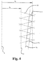
- Fig. 4
- die Ausbildung des Gewindeqürschnittes des selbstsschneidenden Aussengewindes des Kieferimplantates an verschie denen Stellen längs der Achse des Kieferimplantates, in vereinfachter, schematischer Darstellung;
- Fig. 5
- das in Fig. 3A dargestellte Kieferimplantat, in einer seitlichen Ansicht;
- Fig. 6A
- ein Kieferimplantat nach der Erfindung, in einer seitlichen Ansicht; und
- Fig. 6B
- das in Fig. 6A dargestellte Kieferimplantat, in einem Schnitt senkrecht zur Längsachse des Kieferimplantates.
- Fig. 1
- a lower jaw with a denture, including a jaw implant according to the invention, partially and simplified, in a diagram;
- Figure 2A
- a lower jaw with a first tooth replacement, including a jaw implant according to the invention, in a section containing the longitudinal axis of the jaw implant;
- Figure 2B
- a lower jaw with a second tooth replacement, including a jaw implant according to the invention, in a section containing the longitudinal axis of the jaw implant;
- Figure 3A
- a jaw implant according to the invention for a denture according to the invention, in a section through the longitudinal axis of the jaw implant;
- Figure 3B
- a superstructure for a denture according to the invention, in a section through the longitudinal axis of the superstructure;
- Fig. 4
- the formation of the thread cross-section of the self-tapping external thread of the jaw implant at various points along the axis of the jaw implant, in a simplified, schematic representation;
- Fig. 5
- the jaw implant shown in FIG. 3A, in a side view;
- Figure 6A
- a jaw implant according to the invention, in a side view; and
- Figure 6B
- the jaw implant shown in FIG. 6A, in a section perpendicular to the longitudinal axis of the jaw implant.
Es sei an dieser Stelle darauf hingewiesen, dass die Bezeichnungen 'distal' und 'proximal', die eigentlich nur für Teile des menschlichen Körpers oder ggfs. für bereits am menschlichen Körper implantierte Ersatzteile genau zutreffend sind, der Anschaulichkeit wegen auch für das Kieferimplantat und den Zahnersatz verwendet werden.At this point it should be noted that the terms 'distal' and 'proximal', which are actually only for parts of the human body or possibly already on the human Body implanted spare parts are accurate, also for the sake of clarity the jaw implant and dentures are used.
In Fig. 1 ist ausschnittweise ein Unterkiefer 2 eines Patienten mit einem Kieferknochen 4
und dem den Kieferknochen 4 umgebenden Zahnfleisch 6 dargestellt. An der Stelle eines
fehlenden echten Zahnes befindet sich ein Zahnersatz 10, der im wesentlichen aus einem
Kieferimplantat 12 und einer Suprakonstruktion 14 besteht. Der genauere Aufbau des Zahnersatzes
10 und insbesondere der Suprakonstruktion 14 ist aus den Fig. 2A, 2B, 3A und 3B
ersichtlich. 1 shows a section of a
Fig. 2A zeigt einen Zahnersatz 10, der einen einzelnen fehlenden Zahn ersetzt und ein Kieferimplantat
12 sowie eine Suprakonstruktion 14 umfasst. Fig. 2B zeigt einen Zahnersatz
10, welcher gewissermassen brückenartig vier benachbarte Zähne ersetzt, mit zwei Kieferimplantaten
12 und einer darauf abgestützten Suprakonstruktion 14; das in Fig. 2B rechts
dargestellte Ende 14.1 der Suprakonstruktion 14 ersetzt einen hintersten Backenzahn und
ist gewissermassen überhängend angeordnet, während die in Fig. 2B mit 14.4 und 14.2
bezeichneten Anteile der Suprakonstruktion 14 gewissermassen kronenartig und der in Fig.
2B mit 14.3 bezeichnete Anteil der Suprakonstruktion 14 gewissermassen brückenartig angeordnet
sind. 2A shows a
Die Suprakonstruktion 14 gemäss Fig. 2A umfasst einen Verbindungskörper 16, ein Gerüst
18 und eine Verblendung 20, wobei das Gerüst 18 und die Verblendung 20 zusammen eine
Kappe 19 bilden, wie dies aus Fig. 3B ersichtlich ist. Die Verblendung 20 ist der einzige
Bestandteil des Zahnersatzes 10, der bei korrekter Montage in der Mundhöhle des Patienten
sichtbar ist. Das proximale Ende 16.1 des Verbindungskörpers 16 ist im Kieferimplantat 12
verschraubt ist und das distalen Ende 16.2 des Verbindungskörpers 16 ist mit dem Gerüst
18 verbunden, welches seinerseits von der Verblendung 20 ummantelt ist.The
In Fig. 3A ist das Kieferimplantat 12 nach der Erfindung genauer dargestellt. Es weist einen
Implantatfuss 12.1, einen Implantatkörper 12.2 und einen Implantatkopf 12.3 auf. Die Aussenfläche
des Kieferimplantates 12 ist im wesentlichen eine Rotationsfläche, welche zulaufend
ausgebildet ist, wobei der Durchmesser des zur proximalen Lage am Patienten bestimmten
Endes, im folgenden als proximales Implantatende bezeichnet, kleiner ist und der
Durchmesser des zur distalen Lage am Patienten bestimmte Ende, im folgenden als distales
Implantatende bezeichnet, grösser ist.The
Der Implantatfuss 12.1 ist im Längsschnitt abgerundet und seine Aussenfläche weist annähernd
oder genau die Form einer Kugelfläche auf; die axiale Abmessung des der Implantafusses
12.1 kann ggfs. verändert werden, um die totale Höhe des Kieferimplantates 12 an
die im Kieferknochen verfügbare Höhe anzupassen bzw. einen eventuellen Knochenschwund
zu berücksichtigen. Die Aussenfläche des Implantakörpers 12.2 weist im vorliegenden
Ausführungsbeispiel die Form einer Kegelstumpffläche auf, das heisst, dass die Erzeugende
des Implantatkörpers 12.2 eine Gerade ist; es ist aber auch möglich, den Implantatkörper
12.2 so auszubilden, dass die Erzeugende eine Kurve ist. Der Implantatkopf 12.3
besitzt eine Aussenfläche in Form einer Kegelstumpffläche, ist aber stärker der Aussenfläche
des Implantatkopfes 12.3 wecke, im montierten Zustand des Kieferimplantates 10 eine
dichtende Anlagefläche zu bilden, um zu verhindern, dass zwischen Zahnfleisch 6 bzw.
Kieferknochen 4 einerseits und Kieferimplantat 10 anderseits Verschmutzungen eindringen
können, welche Entzündungen verursachen könnten. Sowohl der Implantafuss 12.1 als auch
der Implantakopf 12.3 können auch andere geeignete Formen aufweisen als die oben beschriebenen.The implant foot 12.1 is rounded in longitudinal section and its outer surface has approximately or exactly the shape of a spherical surface; the axial dimension of the implant foot 12.1 can be changed, if necessary, in order to adapt the total height of the
Der Implantatkörper 12.2 ist mit einem selbstschneidenden Aussengewinde 12.4 versehen, dessen genaue Ausbildung weiter unten mit Bezug auf Fig. 4 erläutert wird. Hier sei nur vermerkt, dass es zur Anpassung an den spiegelsymmetrischen Aufbau des Kiefers und die spiegelsymmetrische Beanspruchung der Gebisshälften vorteilhaft sein kann, an den Kieferimplantaten für die eine Kieferseite beispielsweise ein Rechtsgewinde und für die andere, gegenüberliegende Kieferseite entsprechend ein Linksgewinde vorzusehen, obwohl dadurch erhöhte Anforderungen betreffend Herstellung, Lagerhaltung und Fertigkeit des Dentisten auftreten.The implant body 12.2 is provided with a self-tapping external thread 12.4 , the exact design of which is explained below with reference to FIG. 4 . It should only be noted here that in order to adapt to the mirror-symmetrical structure of the jaw and the mirror-symmetrical stress on the half of the teeth, it may be advantageous to provide a right-hand thread on the jaw implants for one jaw side and a left-hand thread for the other, opposite jaw side, although this increases it Requirements regarding the manufacture, storage and skill of the dentist occur.
Das Kieferimplantat 12 weist eine im wesentlichen rotationssymmetrische, zylindrische
Längsausnehmung 12.5 auf, wobei im vorliegenden Beispiel die Längsachse A des selbstschneidenden
Aussengewindes 12.4 mit der Längsachse der Längsausnehmung 12.5 zusammenfallen,
was aber nicht in jedem Falle so sein muss. Die Längsausnehmung 12.5
erstreckt sich im wesentlichen über den Bereich des Implantatkörpers 12.2 und des Implantatkopfes
12.3. Im Bereich des Implantatkörpers 12.2 weist die Längsausnehmung ein Innengewinde
12.6 und im Bereich des Implantatkopfes 12.3 als dichtende Anlagefläche nach
der Montage und als Zentrier- und Führungsfläche während der Montage des Verbindungskörpers
16 einen Innenkonus 12.7 auf.The
Vorzugsweise wird das Innengewinde 12.6 so als Links- bzw. Rechtsgewinde gewählt, dass
ein Einschraubvorgang in dieses Innengewinde 12.6 keine Lockerung des im Kieferknochen
4 eingeschraubten Kieferimplantates 12 zur Folge hat. Zwar hat bei einer solchen Konfiguration
der Gewinde 12.4 und 12.6 ein zu einem späteren Zeitpunkt ggfs. notwendiges Ausschrauben
des Verbindungskörpers 16 tendenziell eine Lockerung des Sitzes des Implantakörpers
12 relativ zum Kieferknochen 4 zur Folge; dies ist aber nicht gravierend, da zu
einem solchen späteren Zeitpunkt das Kieferimplant 12 bereits von neue gebildeter Knochensubstanz
umwachsen und damit gehalten ist.The internal thread 12.6 is preferably selected as a left-hand or right-hand thread such that screwing into this internal thread 12.6 does not result in loosening of the
Die Implantierung des Kieferimplantates 12 spielt sich wie folgt ab: nach der Extraktion der
Reste des zu ersetzenden Zahnes, natürlich einschliesslich der Wurzel, wird im Kieferknochen
eine Ausnehmung zur Aufnahme des Kieferimplantates 12 vorgebohrt. Hierzu wird ein
nicht dargestellter Bohrer verwendet, dessen Aussenfläche im wesentlichen gleich ist wie die
Rotationsfläche des Kieferimplantates 12 und der somit drei Bereiche aufweist, die dem Implantafuss
12.1, dem Implantakörper 12.2 und dem Implantatkopf 12.3 entsprechen. Bei der
anschliessenden Implantierung des Kieferimplantates 12 schneidet sich das selbstschneidende
Aussengewinde 12.4 ausgehend von der Innnenwandung dieser Bohrung in den
Kieferknochen 6 ein. Eine Deformation des Kieferknochens 6, welche diesen zu stark beanspruchen
und ggfs. sprengen würde, findet nicht statt. Eine geringe Spannung im Kieferknochen
6 fördert dagegen erfahrungsgemäss die Bildung von Knochensubstanz und damit das
Umwachsen des Kieferimplantates 12 durch Knochensubstanz des Kieferknochens.The implantation of the
Fig. 3B zeigt die Suprakonstruktion 14, welche hier den Verbindungskörper 16 und die Kappe
19 umfasst. Die Grenze zwischen dem Gerüst 18 und der Kappe 19 ist durch eine gestrichelte
Linie angedeutet. Die Kappe 19 könnte bei geeigneter Materialauswahl auch das Gerüst
18 und die Verblendung 20 integrieren. 3B shows the
Der Verbindungskörper 16 weist einen proximal zu liegen kommenden Teil 16.1 auf, welcher
ein Aussengewinde 16.2 besitzt, das zum Innengewinde 12.6 des Kieferimplantates 12
komplementär ist, und das in das bereits implantierte Kieferimplantat 12 eingeschraubt wird,
um den Verbindungskörper 16 am Kieferimplantat 12 zu fixieren. Der Verbindungskörper 16
besitzt ferner, in Längsrichtung an das Aussengewinde 16.1 anschliessend, eine zulaufende
Fläche 16.2 bzw. einen hier konischen Bereich 16.2 auf, der komplementär zur konischen
Fläche 12.7 bzw. zum Innenkonus 12.7 des Kieferimplantates 12 geformt ist. Der Zweck der
konischen Ausbildung der Flächen 12.7 und 16.2 ist es, eine dichtende gegenseitige Anlage
zu erhalten. Damit vermeidet man das Eindringen von Verunreinigungen zwischen Kieferimplantat
12 und Verbindungskörper 16; wodurch man nicht nur die Bildung von Infektionsherden
verhindert sondern auch ein ggfs. später notwendiges Ausschrauben des Verbindungskörpers
16 aus dem Kieferimplantat 12 erleichtert. An den in proximaler Richtung zulaufenden
konischen Bereich 16.2 des Verbindungskörpers schliesst sich als Positionierungsfläche
16.3 ein zweiter konischer Bereich an, der in distaler Richtung zulaufend ausgebildet ist. The connecting
Dieser zweite konischen Bereich enthält in der Nähe seines distalen Endes eine Ausnehmung
16.4, beispielsweise in Form einer umlaufenden Nut. Am Ort dieser Ausnehmung
16.4 entsteht ein Hohlraum 17, der durch den Verbindungskörper 16 und das Gerüst 18 der
die Kappe 19 begrenzt ist., und der zur Aufnahme eines Klebstoffes oder Zementes oder
des vorderen Endes einer quer einschraubbaren Fixierschraube bestimmt ist, von welcher
nur die Achse B dargestellt ist.This second conical region contains a recess 16.4 in the vicinity of its distal end , for example in the form of a circumferential groove. At the location of this recess 16.4 there is a
Die Kappe 19 weist einen Innenkonus auf, der eine zur Positionierungsfläche 16.3 passende
Komplementärfläche 19.1 bildet bzw. hier komplementär zum Innenkonus 16.3 des Verbindungskörpers
16 ausgebildet ist, der aber keinen der Nut 16.4 des Verbindungskörpers 16
entsprechenden Kragen besitzt. Der dadurch zwischen dem Verbindungskörper 16 und der
Kappe 19 gebildete ringförmige Hohlraum 17 dient wie oben erwähnt zur Aufnahme von
nicht dargestelltem Klebstoff bzw. Zement, mit dessen Hilfe die Kappe 19 in üblicher Weise
am Verbindungskörper 16 befestigt ist.The
Wie schon erwähnt, weist das Aussengewinde 12.4 des Kieferimplanates 12 erfindungsgemäss
eine besondere Form auf. Der Querschnitt des Aussengewindes 12.4 ist abgeleitet
von einem fiktiven Gewinde, dessen Querschnitt ein spitzwinkliges Dreieck 30 ist, das
schraubenlinienförmig um einen fiktiven zylindrischen Körper 32 umläuft. In Fig. 4 sind diese
spitzwinkligen Dreiecke 30 in die Schnittebene bzw. in die Zeichnungsebene gedreht, was
geometrisch nicht ganz korrekt aber sehr anschaulich ist.. Die Achse dieses fiktiven zylindrischen
Körpers 32 fällt mit der Achse A des Kieferimplantates 12 zusammen und ist daher
auch mit A bezeichnet. Der Kerndurchmesser des fiktiven Gewindes ist mit dk und sein
Aussendurchmesser mit da bezeichnet. Das tatsächlich vorhandene Gewinde, dessen Kontur
in Fig. 4 durch einen verdickten Linienzug angegeben ist, unterscheidet sich vom oben
beschriebenen fiktiven Gewinde, indem der Querschnitt des tatsächlichen Gewindes jeweils
an jeder axialen Stelle sein durch einen bestimmten Ausschnitt aus dem Dreieck 30 des
Querschnitts des fiktiven Gewindes gebildet ist. Dabei sind der sich kontinuierlich verändernde
Kerndurchmesser und der sich kontinuierlich verändernde Aussendurchmesser des
tatsächlichen Gewindes durch zwei hier parallele und konische Flächen Kk bzw. Ka bestimmt,
wobei der Öffnungswinkel der entsprechenden Konen weiter oben summarisch als
Öffnungswinkel derjenigen Kegelstumpffläche bezeichnet, die den Implantatkörper 12.2 bildet.
Die konische Fläche Ka bildet die Hüllfläche an den Implantatkörper 12.2, und die konischen
Fläche Kk begrenzt den eigentlichen konischen Implantatkörper 12.2. As already mentioned, the external thread 12.4 of the
Fig. 5 zeigt eine seitliche Ansicht des Kieferimplantates 12 mit dem speziellen selbstschneidenden
Ausssengewinde, das mit Bezug auf Fig. 4 beschrieben wurde, und zwar in geometrisch
korrekter Darstellung. Es ist deutlich zu erkennen, dass die Steigung des selbstschneidenden
Aussengewindes 12.4 so gewählt ist, dass jeweils zwischen benachbarten
Gewindegängen ein Bereich der konischen Aussenfläche Kk des Implantatkörpers 12.2 vorhanden
ist. FIG. 5 shows a side view of the
In den Fig. 6A und 6B ist ein Kieferimplantat 12 nach der Erfindung in einer seitlichen Ansicht
bzw. in einem Schnitt senkrecht zur Achse A dargestellt. Hierbei ist gemäss Fig. 6B
das selbstschneidende Gewinde 12.4 in mehreren Längsbereichen 40 unterbrochen, wobei
in Fig. 6A nur einer dieser Bereiche 40 dargestellt ist; die Längsbereiche 40 bilden Spannuten
für die beim Implantieren des Kieferimplantates 12 entstehenden Knochenspäne des
Kieferknochens 4. Gleichzeitig werden an den Begrenzungen des Restgewindes Schneiden
42 des selbstschneidenden Gewindes 12.4 gebildet. Die in Fig. 6A dargestellten Längsbereiche
40 verlaufen längs den Erzeugenden der Rotationsfläche des Implantakörpers 12.4,
könnten beispielsweise aber auch die Form einer Schraubenlinie haben, mit einem Steigungswinkel,
der einiges grösser ist als der Steigungswinkel des selbstschneidenden Aussengewindes
12.4. 6A and 6B , a
Claims (20)
dadurch gekennzeichnet, dass die Rotationsflächen (Kk , Ka ) im Bereich des Implantatkörpers (12.2) Kegelstumpfflächen sind.Jaw implant ( 12 ) according to claim 1 ,
characterized in that the surfaces of rotation ( K k , K a ) in the region of the implant body ( 12.2 ) are frustoconical surfaces .
dadurch gekennzeichnet, dass die Steigung des selbstschneidenden Aussengewindes (12.4) so gewählt ist, dass einander gegenüberliegende Gewindeflanken benachbarter Gewindegänge im Gewindekern durch Abschnitte der den Implantatkörper (12.2) bildenden Rotationsfläche (Kk ) getrennt sind. Jaw implant ( 12 ) according to at least one of the above claims,
characterized in that the pitch of the self-tapping external thread ( 12.4 ) is selected such that mutually opposite thread flanks of adjacent thread turns in the thread core are separated by sections of the rotary surface ( K k ) forming the implant body ( 12.2 ).
dadurch gekennzeichnet, dass die Flankenwinkel zweier Flanken eines Gewindeganges des selbstschneidenden Aussengewindes (12.4) unter verschiedenen Winkeln zur Rotationsfläche (Kk ) des Implantatkörpers (12.2) angeordnet sind, derart, dass das Aussengewinde (12.4) eine sägezahnähnliche Kontur aufweist.Jaw implant ( 12 ) according to at least one of the above claims,
characterized in that the flank angles of two flanks of a thread of the self-tapping external thread ( 12.4 ) are arranged at different angles to the rotation surface ( K k ) of the implant body ( 12.2 ), such that the external thread ( 12.4 ) has a sawtooth-like contour.
dadurch gekennzeichnet, dass die Flanken eines Gewindeganges des selbstschneidenden Aussengewindes (12.4) unter einem Winkel zusammentreffen, der im Bereich zwischen etwa 0,5° und etwa 40° liegt.Jaw implant ( 12 ) according to at least one of the above claims,
characterized in that the flanks of a thread of the self-tapping external thread ( 12.4 ) meet at an angle which is in the range between approximately 0.5 ° and approximately 40 °.
dadurch gekennzeichnet, dass das selbstschneidende Aussengewinde (12.4) zur Bildung von Schneidkanten (42) längs mindestens eines streifenförmigen Bereiches (40) durch eine Ausnehmung unterbrochen ist, welche in Richtung einer Erzeugenden der Rotationsfläche (Kk ) des Implantatkörpers (12) oder in Richtung einer Schraubenlinie verläuft, deren Steigung grösser ist als die Steigung des selbstschneidenden Aussengewindes (12.4).Jaw implant ( 12 ) according to at least one of the above claims,
characterized in that the self-tapping external thread ( 12.4 ) to form cutting edges ( 42 ) along at least one strip-shaped area ( 40 ) is interrupted by a recess which is in the direction of a generatrix of the surface of rotation ( K k ) of the implant body ( 12 ) or in the direction runs along a helix whose pitch is greater than the pitch of the self-tapping external thread ( 12.4 ).
dadurch gekennzeichnet, dass es einen an das kleindurchmessrige Ende des Implantatkörpers (12.2) anschliessenden Implantatfuss (12.1) aufweist, der sich, vorzugsweise kugelflächenartig, verjüngt. Jaw implant ( 12 ) according to at least one of the above claims,
characterized in that it has an implant foot ( 12.1 ) which adjoins the small-diameter end of the implant body ( 12.2 ) and tapers, preferably in the manner of a spherical surface.
dadurch gekennzeichnet, dass es einen an das grossdurchmessrige Ende des Implantakörpers (12.2) anschliessenden Implantatkopf (12.3) aufweist, dessen Durchmesser mit steigendem Abstand vom Implantatkörper (12,2), vorzugsweise kegelstumpfförmig, zunimmt.Jaw implant ( 12 ) according to at least one of the above claims,
characterized in that it has an implant head ( 12.3 ) adjoining the large-diameter end of the implant body ( 12.2 ), the diameter of which increases with increasing distance from the implant body ( 12,2 ), preferably in the shape of a truncated cone.
dadurch gekennzeichnet, dass es eine sackbohrungsartige Längsausnehmung (12.5) besitzt, welche über mindestens einen Teil ihrer Länge mit einem Innengewinde (12.6) versehen ist.Jaw implant ( 12 ) according to at least one of the above claims,
characterized in that it has a blind bore-like longitudinal recess ( 12.5 ) which is provided with an internal thread ( 12.6 ) over at least part of its length.
dadurch gekennzeichnet, dass die Längsausnehmung (12.5) einen Eintrittsteil (12.7) besitzt, der, vorzugsweise kegelstumpfförmig, zuläuft.Jaw implant ( 12 ) according to at least one of the above claims,
characterized in that the longitudinal recess ( 12.5 ) has an inlet part ( 12.7 ) which tapers, preferably in the shape of a truncated cone.
dadurch gekennzeichnet, dass das Gewinde am Kieferimplantat (12) ein Innengewinde (12.6) und das Gewinde am Verbindungskörper (16) ein Aussengewinde (16.1) ist.Dentures according to claim 11,
characterized in that the thread on the jaw implant ( 12 ) is an internal thread ( 12.6 ) and the thread on the connecting body ( 16 ) is an external thread ( 16.1 ).
dadurch gekennzeichnet, dass die Mittel zum Verbinden des Kieferimplantats (12) mit der Suprakonstruktion (14) ferner einen zulaufenden Bereich (12.7) am distalen Ende des Kieferimplantates (12) und einen komplementären zulaufenden Bereich (16.2) am Verbindungskörper (16) der Suprakonstruktion (14) aufweisen, welcher sich distal an das Aussengewinde (16.1) des Verbindungskörpers (16) anschliesst.Dentures ( 10 ) according to at least one of claims 11 to 12,
characterized in that the means for connecting the jaw implant ( 12 ) to the superstructure ( 14 ) also have a tapering region ( 12.7 ) at the distal end of the jaw implant ( 12 ) and a complementary tapering region ( 16.2 ) on the connecting body ( 16 ) of the superstructure ( 14 ), which connects distally to the external thread ( 16.1 ) of the connecting body ( 16 ).
dadurch gekennzeichnet, dass die Suprakonstruktion (14) den genannten Verbindungskörper (16) sowie eine Kappe (19) aufweist, wobei am Verbindungskörper (16) und an der Kappe (19) Positioniermittel (16.3, 19.1) vorhanden sind, um die Kappe (19) am Verbindungskörper (16) zu positionieren.Dentures ( 10 ) according to at least one of claims 11 to 13,
characterized in that the superstructure ( 14 ) has said connecting body ( 16 ) and a cap ( 19 ), positioning means ( 16.3, 19.1 ) being provided on the connecting body ( 16 ) and on the cap ( 19 ) in order to hold the cap ( 19 ) to position on the connecting body ( 16 ).
dadurch gekennzeichnet, dass die Positioniermittel eine am Verbindungskörper (16) angeordnete Positionierfläche (16.3) und eine an der Kappe (19) angeordnete Komplementärfläche (19.1) umfassen, welche dichtend aneinander anliegen. Dentures ( 10 ) according to claim 14 ,
characterized in that the positioning means comprise a positioning surface ( 16.3 ) arranged on the connecting body ( 16 ) and a complementary surface ( 19.1 ) arranged on the cap ( 19 ), which lie sealingly against one another.
dadurch gekennzeichnet, dass die Positionierfläche (16.3) und die Komplementärfläche (19.1) zulaufend, vorzugsweise kegelstumpfförmig, ausgebildet sind.Dentures ( 10 ) according to claim 15 ,
characterized in that the positioning surface ( 16.3 ) and the complementary surface ( 19.1 ) are tapered, preferably frustoconical.
dadurch gekennzeichnet, dass die Positionierfläche (16.3) und/oder die Komplementärfläche eine Ausnehmung (16.4) aufweisen, derart, dass im Bereich der Ausnehmung (16.4) ein durch die Positionierfläche (16.3) und die Komplementärfläche (19.1) begrenzter Raum (17) gebildet ist.Dentures ( 10 ) according to claim 14 ,
characterized in that the positioning surface ( 16.3 ) and / or the complementary surface have a recess ( 16.4 ) such that in the region of the recess ( 16.4 ) a space ( 17 ) delimited by the positioning surface ( 16.3 ) and the complementary surface ( 19.1 ) is formed is.
dadurch gekennzeichnet, dass die Kappe (19) durch ein Gerüst (18) und eine das Gerüst (18) ummantelnde Verblendung (20) gebildet ist.Dentures ( 10 ) according to at least one of claims 11 to 17,
characterized in that the cap ( 19 ) is formed by a frame ( 18 ) and a veneer ( 20 ) encasing the frame ( 18 ).
dadurch gekennzeichnet, dass auf einem Kieferimplantat (12) eine Suprakonstruktion (14) abgestützt ist, um einen Ersatz für mindestens zwei fehlende Zähne zu bilden.Dentures ( 10 ) according to at least one of claims 11 to 18,
characterized in that a superstructure ( 14 ) is supported on a jaw implant ( 12 ) to form a replacement for at least two missing teeth.
dadurch gekennzeichnet, dass auf zwei Kieferimplantaten (12) eine Suprakonstruktion (14) abgestützt ist, um im Bereich zwischen den Kieferimplantaten (12) und/oder ausserhalb dieses Bereiches einen Ersatz für eine Reihe von fehlenden Zähnen zu bilden.Dentures ( 10 ) according to at least one of claims 11 to 18 ,
characterized in that a superstructure ( 14 ) is supported on two jaw implants ( 12 ) in order to form a replacement for a number of missing teeth in the area between the jaw implants ( 12 ) and / or outside of this area.
Priority Applications (2)
| Application Number | Priority Date | Filing Date | Title |
|---|---|---|---|
| DE50014816T DE50014816D1 (en) | 2000-09-12 | 2000-09-12 | jaw implant |
| EP00119812A EP1186275B1 (en) | 2000-09-12 | 2000-09-12 | Dental implant |
Applications Claiming Priority (1)
| Application Number | Priority Date | Filing Date | Title |
|---|---|---|---|
| EP00119812A EP1186275B1 (en) | 2000-09-12 | 2000-09-12 | Dental implant |
Publications (2)
| Publication Number | Publication Date |
|---|---|
| EP1186275A1 true EP1186275A1 (en) | 2002-03-13 |
| EP1186275B1 EP1186275B1 (en) | 2007-11-28 |
Family
ID=8169812
Family Applications (1)
| Application Number | Title | Priority Date | Filing Date |
|---|---|---|---|
| EP00119812A Expired - Lifetime EP1186275B1 (en) | 2000-09-12 | 2000-09-12 | Dental implant |
Country Status (2)
| Country | Link |
|---|---|
| EP (1) | EP1186275B1 (en) |
| DE (1) | DE50014816D1 (en) |
Cited By (2)
| Publication number | Priority date | Publication date | Assignee | Title |
|---|---|---|---|---|
| US7726969B2 (en) | 2007-05-12 | 2010-06-01 | Walther Gerd Axel | Dental implant, in particular of ceramic material |
| EP3763320A1 (en) * | 2019-07-08 | 2021-01-13 | Anthogyr | Improved self-tapping dental implant |
Citations (3)
| Publication number | Priority date | Publication date | Assignee | Title |
|---|---|---|---|---|
| US5000686A (en) * | 1990-01-02 | 1991-03-19 | Implant Innovations, Inc. | Dental implant fixture |
| US5556280A (en) * | 1994-05-31 | 1996-09-17 | Pelak; Mark S. | Method and apparatus for appliance mounting |
| WO1999038451A1 (en) * | 1998-02-03 | 1999-08-05 | Lifecore Biomedical, Inc. | Self-tapping screw type dental implant |
Family Cites Families (2)
| Publication number | Priority date | Publication date | Assignee | Title |
|---|---|---|---|---|
| DE3241963C1 (en) * | 1982-11-12 | 1984-04-26 | Feldmühle AG, 4000 Düsseldorf | Helical jaw implant |
| IT1307923B1 (en) * | 1999-01-25 | 2001-11-29 | Hofmann S A S Di Roberto Hofma | ENDOSSEO DENTAL IMPLANT DEVICE. |
-
2000
- 2000-09-12 EP EP00119812A patent/EP1186275B1/en not_active Expired - Lifetime
- 2000-09-12 DE DE50014816T patent/DE50014816D1/en not_active Expired - Fee Related
Patent Citations (3)
| Publication number | Priority date | Publication date | Assignee | Title |
|---|---|---|---|---|
| US5000686A (en) * | 1990-01-02 | 1991-03-19 | Implant Innovations, Inc. | Dental implant fixture |
| US5556280A (en) * | 1994-05-31 | 1996-09-17 | Pelak; Mark S. | Method and apparatus for appliance mounting |
| WO1999038451A1 (en) * | 1998-02-03 | 1999-08-05 | Lifecore Biomedical, Inc. | Self-tapping screw type dental implant |
Cited By (3)
| Publication number | Priority date | Publication date | Assignee | Title |
|---|---|---|---|---|
| US7726969B2 (en) | 2007-05-12 | 2010-06-01 | Walther Gerd Axel | Dental implant, in particular of ceramic material |
| EP3763320A1 (en) * | 2019-07-08 | 2021-01-13 | Anthogyr | Improved self-tapping dental implant |
| WO2021005481A1 (en) * | 2019-07-08 | 2021-01-14 | Anthogyr | Improved self-tapping dental implant |
Also Published As
| Publication number | Publication date |
|---|---|
| EP1186275B1 (en) | 2007-11-28 |
| DE50014816D1 (en) | 2008-01-10 |
Similar Documents
| Publication | Publication Date | Title |
|---|---|---|
| DE3241963C1 (en) | Helical jaw implant | |
| EP1100396B1 (en) | Implant for holding and/or forming a dental prosthesis or artificial finger joint | |
| EP1100395B1 (en) | Device for holding and/or creating a dental prosthesis | |
| DE69934313T2 (en) | DENTAL IMPLANT | |
| EP1617783B1 (en) | Dental implant | |
| EP1786354B1 (en) | Dental implant system | |
| DE3421056A1 (en) | JAW IMPLANT FOR THE ADMISSION OF A DENTAL SPARE CARRIER | |
| EP1850784A2 (en) | Tooth implant | |
| WO2010048944A1 (en) | Dental implant for insertion into a jawbone and for fastening a tooth replacement | |
| DE102006018726A1 (en) | Dental implant and process for its preparation | |
| DE4326841A1 (en) | Implant set | |
| DE19803172C2 (en) | Subgingival jaw implant | |
| EP1943979B1 (en) | Dental implant | |
| DE10236125B4 (en) | Screw-in self-tapping dental implant | |
| EP1186275B1 (en) | Dental implant | |
| EP1713411B1 (en) | Dental implant | |
| CH693733A5 (en) | Jaw implant and oral surgery. | |
| WO2014090358A1 (en) | One-part or multi-part implant system comprising a mounting element having one or more outer rings | |
| EP0207211B1 (en) | Implantable fixing means for dentures | |
| EP1205158A1 (en) | Dental implant | |
| DE3828013C2 (en) | ||
| DE19719451C1 (en) | Dental pin arrangement with a crownable structure | |
| DE4035172C2 (en) | ||
| DE10114627A1 (en) | implant | |
| DE102015103288A1 (en) | Implant system and method for implanting a dental implant |
Legal Events
| Date | Code | Title | Description |
|---|---|---|---|
| PUAI | Public reference made under article 153(3) epc to a published international application that has entered the european phase |
Free format text: ORIGINAL CODE: 0009012 |
|
| AK | Designated contracting states |
Kind code of ref document: A1 Designated state(s): AT BE CH CY DE DK ES FI FR GB GR IE IT LI LU MC NL PT SE |
|
| AX | Request for extension of the european patent |
Free format text: AL;LT;LV;MK;RO;SI |
|
| 17P | Request for examination filed |
Effective date: 20020503 |
|
| AKX | Designation fees paid |
Free format text: AT BE CH CY DE DK ES FI FR GB GR IE IT LI LU MC NL PT SE |
|
| 17Q | First examination report despatched |
Effective date: 20031024 |
|
| APBN | Date of receipt of notice of appeal recorded |
Free format text: ORIGINAL CODE: EPIDOSNNOA2E |
|
| APBR | Date of receipt of statement of grounds of appeal recorded |
Free format text: ORIGINAL CODE: EPIDOSNNOA3E |
|
| APBK | Appeal reference recorded |
Free format text: ORIGINAL CODE: EPIDOSNREFNE |
|
| APAF | Appeal reference modified |
Free format text: ORIGINAL CODE: EPIDOSCREFNE |
|
| APBT | Appeal procedure closed |
Free format text: ORIGINAL CODE: EPIDOSNNOA9E |
|
| GRAP | Despatch of communication of intention to grant a patent |
Free format text: ORIGINAL CODE: EPIDOSNIGR1 |
|
| RTI1 | Title (correction) |
Free format text: DENTAL IMPLANT |
|
| GRAS | Grant fee paid |
Free format text: ORIGINAL CODE: EPIDOSNIGR3 |
|
| GRAA | (expected) grant |
Free format text: ORIGINAL CODE: 0009210 |
|
| AK | Designated contracting states |
Kind code of ref document: B1 Designated state(s): AT BE CH CY DE DK ES FI FR GB GR IE IT LI LU MC NL PT SE |
|
| REG | Reference to a national code |
Ref country code: IE Ref legal event code: FG4D Free format text: LANGUAGE OF EP DOCUMENT: GERMAN |
|
| REG | Reference to a national code |
Ref country code: CH Ref legal event code: EP |
|
| REF | Corresponds to: |
Ref document number: 50014816 Country of ref document: DE Date of ref document: 20080110 Kind code of ref document: P |
|
| PG25 | Lapsed in a contracting state [announced via postgrant information from national office to epo] |
Ref country code: ES Free format text: LAPSE BECAUSE OF FAILURE TO SUBMIT A TRANSLATION OF THE DESCRIPTION OR TO PAY THE FEE WITHIN THE PRESCRIBED TIME-LIMIT Effective date: 20080311 Ref country code: SE Free format text: LAPSE BECAUSE OF FAILURE TO SUBMIT A TRANSLATION OF THE DESCRIPTION OR TO PAY THE FEE WITHIN THE PRESCRIBED TIME-LIMIT Effective date: 20080228 Ref country code: NL Free format text: LAPSE BECAUSE OF FAILURE TO SUBMIT A TRANSLATION OF THE DESCRIPTION OR TO PAY THE FEE WITHIN THE PRESCRIBED TIME-LIMIT Effective date: 20071128 |
|
| NLV1 | Nl: lapsed or annulled due to failure to fulfill the requirements of art. 29p and 29m of the patents act | ||
| PG25 | Lapsed in a contracting state [announced via postgrant information from national office to epo] |
Ref country code: FI Free format text: LAPSE BECAUSE OF FAILURE TO SUBMIT A TRANSLATION OF THE DESCRIPTION OR TO PAY THE FEE WITHIN THE PRESCRIBED TIME-LIMIT Effective date: 20071128 |
|
| GBV | Gb: ep patent (uk) treated as always having been void in accordance with gb section 77(7)/1977 [no translation filed] | ||
| PG25 | Lapsed in a contracting state [announced via postgrant information from national office to epo] |
Ref country code: DK Free format text: LAPSE BECAUSE OF FAILURE TO SUBMIT A TRANSLATION OF THE DESCRIPTION OR TO PAY THE FEE WITHIN THE PRESCRIBED TIME-LIMIT Effective date: 20071128 |
|
| EN | Fr: translation not filed | ||
| PG25 | Lapsed in a contracting state [announced via postgrant information from national office to epo] |
Ref country code: PT Free format text: LAPSE BECAUSE OF FAILURE TO SUBMIT A TRANSLATION OF THE DESCRIPTION OR TO PAY THE FEE WITHIN THE PRESCRIBED TIME-LIMIT Effective date: 20080428 |
|
| REG | Reference to a national code |
Ref country code: IE Ref legal event code: FD4D |
|
| PLBE | No opposition filed within time limit |
Free format text: ORIGINAL CODE: 0009261 |
|
| STAA | Information on the status of an ep patent application or granted ep patent |
Free format text: STATUS: NO OPPOSITION FILED WITHIN TIME LIMIT |
|
| PG25 | Lapsed in a contracting state [announced via postgrant information from national office to epo] |
Ref country code: FR Free format text: LAPSE BECAUSE OF FAILURE TO SUBMIT A TRANSLATION OF THE DESCRIPTION OR TO PAY THE FEE WITHIN THE PRESCRIBED TIME-LIMIT Effective date: 20080912 Ref country code: IE Free format text: LAPSE BECAUSE OF FAILURE TO SUBMIT A TRANSLATION OF THE DESCRIPTION OR TO PAY THE FEE WITHIN THE PRESCRIBED TIME-LIMIT Effective date: 20071128 |
|
| 26N | No opposition filed |
Effective date: 20080829 |
|
| PG25 | Lapsed in a contracting state [announced via postgrant information from national office to epo] |
Ref country code: GB Free format text: LAPSE BECAUSE OF FAILURE TO SUBMIT A TRANSLATION OF THE DESCRIPTION OR TO PAY THE FEE WITHIN THE PRESCRIBED TIME-LIMIT Effective date: 20071128 |
|
| PG25 | Lapsed in a contracting state [announced via postgrant information from national office to epo] |
Ref country code: GR Free format text: LAPSE BECAUSE OF FAILURE TO SUBMIT A TRANSLATION OF THE DESCRIPTION OR TO PAY THE FEE WITHIN THE PRESCRIBED TIME-LIMIT Effective date: 20080229 |
|
| BERE | Be: lapsed |
Owner name: HERMANN, WERNER Effective date: 20080930 |
|
| PG25 | Lapsed in a contracting state [announced via postgrant information from national office to epo] |
Ref country code: MC Free format text: LAPSE BECAUSE OF NON-PAYMENT OF DUE FEES Effective date: 20080930 |
|
| PGFP | Annual fee paid to national office [announced via postgrant information from national office to epo] |
Ref country code: CH Payment date: 20090318 Year of fee payment: 9 |
|
| PG25 | Lapsed in a contracting state [announced via postgrant information from national office to epo] |
Ref country code: BE Free format text: LAPSE BECAUSE OF NON-PAYMENT OF DUE FEES Effective date: 20080930 Ref country code: CY Free format text: LAPSE BECAUSE OF FAILURE TO SUBMIT A TRANSLATION OF THE DESCRIPTION OR TO PAY THE FEE WITHIN THE PRESCRIBED TIME-LIMIT Effective date: 20071128 |
|
| PG25 | Lapsed in a contracting state [announced via postgrant information from national office to epo] |
Ref country code: DE Free format text: LAPSE BECAUSE OF NON-PAYMENT OF DUE FEES Effective date: 20090401 |
|
| PG25 | Lapsed in a contracting state [announced via postgrant information from national office to epo] |
Ref country code: AT Free format text: LAPSE BECAUSE OF NON-PAYMENT OF DUE FEES Effective date: 20080912 |
|
| REG | Reference to a national code |
Ref country code: CH Ref legal event code: PL |
|
| PG25 | Lapsed in a contracting state [announced via postgrant information from national office to epo] |
Ref country code: LU Free format text: LAPSE BECAUSE OF NON-PAYMENT OF DUE FEES Effective date: 20080912 |
|
| PG25 | Lapsed in a contracting state [announced via postgrant information from national office to epo] |
Ref country code: CH Free format text: LAPSE BECAUSE OF NON-PAYMENT OF DUE FEES Effective date: 20090930 Ref country code: LI Free format text: LAPSE BECAUSE OF NON-PAYMENT OF DUE FEES Effective date: 20090930 |
|
| PG25 | Lapsed in a contracting state [announced via postgrant information from national office to epo] |
Ref country code: IT Free format text: LAPSE BECAUSE OF NON-PAYMENT OF DUE FEES Effective date: 20080930 |