EP1184568A2 - Kraftstoffpumpe - Google Patents
Kraftstoffpumpe Download PDFInfo
- Publication number
- EP1184568A2 EP1184568A2 EP01307398A EP01307398A EP1184568A2 EP 1184568 A2 EP1184568 A2 EP 1184568A2 EP 01307398 A EP01307398 A EP 01307398A EP 01307398 A EP01307398 A EP 01307398A EP 1184568 A2 EP1184568 A2 EP 1184568A2
- Authority
- EP
- European Patent Office
- Prior art keywords
- pumping
- fuel
- plunger
- tappet
- flow path
- Prior art date
- Legal status (The legal status is an assumption and is not a legal conclusion. Google has not performed a legal analysis and makes no representation as to the accuracy of the status listed.)
- Granted
Links
Images


Classifications
-
- F—MECHANICAL ENGINEERING; LIGHTING; HEATING; WEAPONS; BLASTING
- F04—POSITIVE - DISPLACEMENT MACHINES FOR LIQUIDS; PUMPS FOR LIQUIDS OR ELASTIC FLUIDS
- F04B—POSITIVE-DISPLACEMENT MACHINES FOR LIQUIDS; PUMPS
- F04B1/00—Multi-cylinder machines or pumps characterised by number or arrangement of cylinders
- F04B1/04—Multi-cylinder machines or pumps characterised by number or arrangement of cylinders having cylinders in star- or fan-arrangement
- F04B1/053—Multi-cylinder machines or pumps characterised by number or arrangement of cylinders having cylinders in star- or fan-arrangement with actuating or actuated elements at the inner ends of the cylinders
-
- F—MECHANICAL ENGINEERING; LIGHTING; HEATING; WEAPONS; BLASTING
- F02—COMBUSTION ENGINES; HOT-GAS OR COMBUSTION-PRODUCT ENGINE PLANTS
- F02M—SUPPLYING COMBUSTION ENGINES IN GENERAL WITH COMBUSTIBLE MIXTURES OR CONSTITUENTS THEREOF
- F02M59/00—Pumps specially adapted for fuel-injection and not provided for in groups F02M39/00 -F02M57/00, e.g. rotary cylinder-block type of pumps
- F02M59/02—Pumps specially adapted for fuel-injection and not provided for in groups F02M39/00 -F02M57/00, e.g. rotary cylinder-block type of pumps of reciprocating-piston or reciprocating-cylinder type
- F02M59/04—Pumps specially adapted for fuel-injection and not provided for in groups F02M39/00 -F02M57/00, e.g. rotary cylinder-block type of pumps of reciprocating-piston or reciprocating-cylinder type characterised by special arrangement of cylinders with respect to piston-driving shaft, e.g. arranged parallel to that shaft or swash-plate type pumps
- F02M59/06—Pumps specially adapted for fuel-injection and not provided for in groups F02M39/00 -F02M57/00, e.g. rotary cylinder-block type of pumps of reciprocating-piston or reciprocating-cylinder type characterised by special arrangement of cylinders with respect to piston-driving shaft, e.g. arranged parallel to that shaft or swash-plate type pumps with cylinders arranged radially to driving shaft, e.g. in V or star arrangement
-
- F—MECHANICAL ENGINEERING; LIGHTING; HEATING; WEAPONS; BLASTING
- F02—COMBUSTION ENGINES; HOT-GAS OR COMBUSTION-PRODUCT ENGINE PLANTS
- F02M—SUPPLYING COMBUSTION ENGINES IN GENERAL WITH COMBUSTIBLE MIXTURES OR CONSTITUENTS THEREOF
- F02M59/00—Pumps specially adapted for fuel-injection and not provided for in groups F02M39/00 -F02M57/00, e.g. rotary cylinder-block type of pumps
- F02M59/02—Pumps specially adapted for fuel-injection and not provided for in groups F02M39/00 -F02M57/00, e.g. rotary cylinder-block type of pumps of reciprocating-piston or reciprocating-cylinder type
- F02M59/10—Pumps specially adapted for fuel-injection and not provided for in groups F02M39/00 -F02M57/00, e.g. rotary cylinder-block type of pumps of reciprocating-piston or reciprocating-cylinder type characterised by the piston-drive
- F02M59/102—Mechanical drive, e.g. tappets or cams
-
- F—MECHANICAL ENGINEERING; LIGHTING; HEATING; WEAPONS; BLASTING
- F04—POSITIVE - DISPLACEMENT MACHINES FOR LIQUIDS; PUMPS FOR LIQUIDS OR ELASTIC FLUIDS
- F04B—POSITIVE-DISPLACEMENT MACHINES FOR LIQUIDS; PUMPS
- F04B1/00—Multi-cylinder machines or pumps characterised by number or arrangement of cylinders
- F04B1/04—Multi-cylinder machines or pumps characterised by number or arrangement of cylinders having cylinders in star- or fan-arrangement
- F04B1/0404—Details or component parts
- F04B1/0426—Arrangements for pressing the pistons against the actuated cam; Arrangements for connecting the pistons to the actuated cam
- F04B1/043—Hydraulic arrangements
-
- F—MECHANICAL ENGINEERING; LIGHTING; HEATING; WEAPONS; BLASTING
- F04—POSITIVE - DISPLACEMENT MACHINES FOR LIQUIDS; PUMPS FOR LIQUIDS OR ELASTIC FLUIDS
- F04B—POSITIVE-DISPLACEMENT MACHINES FOR LIQUIDS; PUMPS
- F04B23/00—Pumping installations or systems
- F04B23/04—Combinations of two or more pumps
- F04B23/06—Combinations of two or more pumps the pumps being all of reciprocating positive-displacement type
-
- F—MECHANICAL ENGINEERING; LIGHTING; HEATING; WEAPONS; BLASTING
- F04—POSITIVE - DISPLACEMENT MACHINES FOR LIQUIDS; PUMPS FOR LIQUIDS OR ELASTIC FLUIDS
- F04B—POSITIVE-DISPLACEMENT MACHINES FOR LIQUIDS; PUMPS
- F04B5/00—Machines or pumps with differential-surface pistons
Definitions
- the invention relates to a fuel pump for use in supplying fuel to a compression ignition internal combustion engine.
- a known high pressure fuel pump for use in supplying fuel to a compression ignition internal combustion engine comprises a pumping plunger reciprocable within a plunger bore under the influence of a cam drive arrangement so as to pressurise fuel within a pumping chamber.
- the plunger moves inwardly within the plunger bore to reduce the volume of the pumping chamber, thereby causing the pressure of fuel therein to be increased.
- fluid is delivered from the pumping chamber through a suitable valve arrangement.
- the plunger performs a return stroke in which the plunger moves in an outward direction within the plunger bore to increase the volume of the pumping chamber.
- fuel is delivered to the pumping chamber through an inlet valve arrangement ready for pressurisation during the next forward stroke.
- EP 0 972 936 describes a fuel pump in which the return stroke of the pumping plunger is performed by supplying fluid to a working chamber defined, in part, by a tappet assembly which acts to transmit a force from the cam arrangement to the pumping plunger during the forward stroke of the plunger.
- a force due to fuel pressure within the working chamber acts on the tappet assembly and serves to drive the plunger to perform the return stroke, the pumping plunger moving outwardly from the plunger bore to increase the volume of pump chamber.
- a fuel pump comprising a plurality of radially spaced pumping arrangements, each of which includes a pumping plunger which is reciprocable within a plunger bore formed in a pump housing under the influence of a driven tappet member which acts to transmit a force to the pumping plunger during a forward stroke thereof, the plunger bore defining a pumping chamber within which pressurisation of fuel to a relatively high level occurs upon reciprocal movement of the pumping plunger within the plunger bore, wherein an end region of the tappet member is provided with a further bore, a surface associated with the end region defining, in part, an annular auxiliary pumping chamber for fuel, the further bore defining a working chamber arranged to receive fuel to generate a force on the tappet member which acts in a return direction so as to increase the volume of the pumping chamber during a return stroke of the pumping plunger, the fuel pump further comprising a transfer pressure flow path providing communication between the auxiliary pumping chamber of a first pumping arrangement and the pumping
- reciprocal movement of the pumping plungers within their respective bores is phased such that pressurisation of fuel within the auxiliary pumping chamber of one pumping arrangement causes fuel, pressurised to a first, slightly pressurised level, to be delivered to the pumping chamber of at least one of the other pumping arrangement, wherein pressurisation to a relatively high level occurs, pressurised fuel being delivered from the pumping chamber(s) to a delivery passage.
- the delivery passage may, for example, deliver fuel to a common rail of a common rail fuel system or an accumulator.
- inward movement of the pumping plunger within the plunger bore to cause pressurisation of fuel within the pumping chamber shall be referred to as “the forward stroke”
- the return stroke outward movement of the pumping plunger from the plunger bore to increase the volume of the pumping chamber
- the invention provides the advantage that the auxiliary pumping chamber is defined within the pump housing, rather than being a separate pump attached to the main pump housing.
- the cost and weight of the pump is therefore reduced, as is the volume occupied by the pump.
- the need for a return spring to effect the return stroke of the pumping plunger is also removed, as the return stroke of the pumping plunger is driven by means of fuel within the working chamber.
- the auxiliary pumping chamber of each pumping arrangement is defined by the end region of the tappet member and a tappet bore provided in the pump housing.
- each pumping arrangement is preferably provided with an associated spring arrangement which serves to urge the pumping plunger outwardly from the plunger bore.
- the provision of the spring arrangement provides the advantage that, upon engine start up, the pumping plunger and the tappet member are caused to reciprocate, thereby drawing fuel into the auxiliary pumping chamber. Only fuel displaced from the auxiliary pumping chamber is delivered to the pumping chamber.
- the working chambers are in fluid communication with one another through a common tappet return flow path, wherein the common tappet return flow path is provided with a damping arrangement which serves to minimise pressure variations within the common tappet return flow path.
- the pump may be relatively compact.
- any leakage flow from the tappet return flow path and the working chamber is recycled to the transfer pressure flow path, rather than being lost from the pump, subject to a relatively small amount of fuel leakage directly from the tappet return flow path as described in further detail hereinafter. Pump losses can therefore be limited to a relatively low level.
- the tappet member is shaped to ensure the working chamber communicates with the tappet return flow path throughout the full extent of the forward stroke and throughout the full extent of the return stroke.
- the transfer pressure flow path is provided with a metering valve arrangement which serves to regulate the rate of fuel flow into the pumping chambers.
- Each of the auxiliary pumping chambers is preferably provided with a respective inlet valve arrangement for controlling the flow of fuel into the associated auxiliary pumping chamber and a respective outlet valve arrangement for controlling the flow of fuel between the associated auxiliary pumping chamber and the transfer pressure flow path.
- each inlet valve arrangement is constructed and adapted to ensure the flow of fuel into the associated auxiliary pumping chamber is substantially unrestricted.
- each outlet valve arrangement is preferably constructed and adapted to ensure the flow of fuel from the associated auxiliary pumping chamber is substantially unrestricted. In this way, the flow of fuel within the transfer pressure flow path to the pumping chambers can be maintained at a substantially constant flow rate.
- the inlet and outlet valve arrangements associated with the auxiliary pumping chamber can be arranged to share a common flow passage through which fuel flows to and from the auxiliary pumping chamber.
- each plunger bore has, associated therewith, an additional inlet valve arrangement which serves to control the flow of fuel into the respective pumping chamber and an additional outlet valve arrangement which serves to control the flow of fuel from the respective pumping chamber to a delivery flow path.
- the tappet member of each pumping arrangement is provided with a radially extending drilling which provides communication between the associated working chamber and an aperture provided on the surface of said tappet member, the aperture communicating the common tappet return flow path.
- the aperture is of relatively small size compared to an outer diameter of the associated tappet member.
- the aperture may take the form of a slot having an outer periphery which is small compared with the outer diameter dimension of the associated tappet member.
- the fuel pump comprises three radially spaced pumping plungers, each having an associated auxiliary pumping chamber defined by the tappet member.
- a high pressure fuel pump for use in a fuel injection system of an internal combustion engine.
- the high pressure fuel pump is suitable for use in delivering high pressure fuel to an accumulator or the common rail of a common rail fuel system.
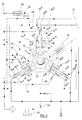
- the pump comprises three equi-angularly spaced pumping arrangements, 10a, 10b, 10c, which extend radially around a drive shaft 12 within a pump housing 18.
- the drive shaft 12 carries a cam arrangement 14 which defines a cam surface, the cam surface being cooperable with roller members 16a, 16b, 16c associated with the pumping arrangements 10a, 10b, 10c respectively.
- the pumping arrangements 10a, 10b, 10c are substantially the same as each other and therefore, for convenience, only one of the pumping arrangements 10a will be described in detail.
- the pump housing 18 is provided with a first plunger bore 19a within which a pumping plunger 20a is reciprocable.
- the plunger bore 19a defines a pumping chamber 22a to which fuel is delivered, in use.
- the pumping plunger 20a engages a tappet member 24a forming part of a tappet assembly, referred to generally as 17a, the tappet member 24a being slidably mounted in a further tappet bore 26a provided in the pump housing 18.
- the region 18a of the pump housing 18 within which the plunger bore 19a is provided may be referred to as the 'plunger support cylinder'.
- the tappet member 24a carries the roller member 16a associated with the pumping arrangement 10a such that, upon rotation of the drive shaft 12 about its axis, the roller member 16a and the tappet member 24a transmit reciprocating motion to the pumping plunger 20a.
- the reciprocating motion of the pumping plunger 20a is such that, during inward movement of the pumping plunger 20a within the plunger bore 19a (the forward stroke), the pumping plunger 20a is moved to reduce the volume of the pumping chamber 22a.
- the pumping chamber 22a has an associated outlet valve arrangement 28a (as shown in Figure 1) having an associated spring 29a which serves to urge an outlet valve member against a seating to prevent fuel flow from the pumping chamber 22a into a fuel delivery path 31.
- the outlet valve member When fuel pressure within the pumping chamber 22a is increased beyond a predetermined amount, the outlet valve member is caused to lift away from the seating to permit pressurised fuel to flow into the delivery path 31 and to a common rail or accumulator 30 associated with the fuel system. It will be appreciated that high pressure fuel is also delivered from the pumping chambers 22b, 22c associated with the pumping arrangements 10b, 10c to the common rail 30 in a similar manner. Closure of the outlet valve arrangement 28a occurs under the action of the spring 29a when the pumping plunger 22a has reached top-dead-centre and starts the return stroke.
- the pumping chamber 22a also has an associated inlet valve arrangement 32a, the inlet valve arrangement 32a having an open position in which fuel is delivered to the pumping chamber 22a through a primary, transfer pressure supply path 34.
- the primary supply path 34 receives fuel from a secondary fuel supply path 43 through a metering valve arrangement 36 which serves to regulate, by means of a variable restriction, the rate of flow of fuel to the pumping chamber 22a.
- the flow of fuel through the primary supply path 34 is therefore a metered flow of fuel.
- the secondary fuel supply path 43 receives fuel at transfer pressure, as will be described in further detail hereinafter, and may therefore be referred to as a "transfer pressure flow path".
- a pressure regulator 38 serves to regulate fuel pressure at the inlet of the metering valve arrangement 36, to permit excess fuel to return from the transfer pressure flow path 43 to a feed path 33 in communication with a fuel reservoir 35.
- pumping arrangements 10b, 10c also have associated inlet valve arrangements 32b, 32c respectively through which fuel is delivered to the respective pumping chamber 22b, 22c from the primary fuel supply path 34 in a similar manner, the primary fuel supply path 34 being common to all three pump arrangements 10a, 10b, 10c.
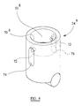
- An end region of the tappet member 24a is provided with an additional bore 70a which extends a part of the way along the longitudinal axis of the tappet member 24a .
- the end region of the tappet member 24a forming part of the pumping arrangement 10a defines, together with the tappet bore 26a within which the tappet member 24a is reciprocable, an annular auxiliary pumping chamber 40a for fuel.
- the auxiliary chamber 40a has an associated inlet valve arrangement 42a which serves to control the supply of fuel to the auxiliary chamber 40a from the feed path 33, fuel being delivered from the feed path 33, through the inlet valve arrangement 42a, to the auxiliary chamber 40a via a flow passage 46 (as shown in Figure 3) provided in the pump housing 18.
- the auxiliary chamber 40a also has an associated outlet valve arrangement 44b which serves to control the flow of fuel from the auxiliary chamber 40a, through the flow passage 46, into the transfer pressure flow path 43.
- auxiliary pumping chambers 40b, 40c also have inlet and outlet valve arrangements 42b, 42c and 44b, 44c respectively associated therewith, fuel delivered through the outlet valve arrangements 44b, 44c from the associated auxiliary pumping chamber 40b, 40c also being delivered to the secondary supply path 43.
- the additional bore 70a which extends a part of the way along the longitudinal axis of the tappet member 24a communicates, via radially extending drillings 72, with axial slots or apertures 74 provided on the surface of the tappet member 24a.
- the bore 70a provided in the tappet member 24a and a region of the housing 18 together define a working chamber 51a for fuel.
- the working chamber 51a communicates, via the drillings 72 and the apertures 74 provided in the tappet member 24a, with a further flow path 52 for fuel, the further flow path 52 also being in communication with corresponding working chambers associated with the other pumping arrangements 10b, 10c.
- the working chamber 51a is arranged such that the pressure of fuel within the working chamber 51a serves to urge the plunger member 20a and the tappet member 24a in a radially inward direction (i.e. outwardly from their respective bores) to perform a return stroke.
- the tappet members 24b, 24c are also provided with corresponding apertures and drillings to provide communication between the respective working chamber 51b, 51c and the further flow path 52, the apertures in the tappet members 24a, 24b, 24c being arranged to ensure the working chambers 51a, 51b, 51c remain in communication with the further flow path 52 throughout the full range of movement of the tappet members 24a, 24b, 24c on both the forward and return strokes.
- Communication between the working chambers 51a, 51b, 51c through the further flow path 52 provides a means for returning each of the tappet members 24a, 24b, 24c to their starting positions (outermost position within their respective bores) for each pumping stroke.
- the further flow path 52 may therefore be referred to as 'tappet return flow path' through which fuel flows, in both directions between adjacent working chambers, depending on the phase of motion of the tappet members 24a, 24b, 24c and, hence, the pumping plungers 20a, 20b, 20c.
- the tappet return flow path 52 receives fuel from the transfer pressure flow path 43 through an auxiliary flow path 56 provided with a top-up valve arrangement 58.
- Fuel leakage from the tappet return circuit 52, 51a, 51b, 51c through clearances between the tappet members 24a, 24b, 24c and their respective bores 26a, 26b, 26c is able to flow, via a backleak flow passage 60, to the fuel reservoir 35 through a backleak valve arrangement 63.
- Fuel is also able to flow, through a restricted flow path 54, from the transfer pressure flow path 43 into the central region of the housing 18 to provide lubrication and cooling of the cam surfaces, the rollers 16a, 16b, 16c and the tappet members 24a, 24b, 24c.
- the pumping plunger 20a is retained in position within the tappet assembly 17a by means of a spring arrangement 48 arranged within the working chamber 51a, the spring arrangement 48 acting on the pumping plunger 20a in a radially inward direction to ensure that the pumping plunger 20a, tappet member 24a, roller member 16a and the surface of the cam arrangement 14 remain properly in contact during an initial brief period of rotation, during which the tappet return flow path 52 may be incompletely filled.
- the tappet return flow path 52 must be completely filled for normal reciprocation to take place, and therefore for the auxiliary pumping action to supply correctly the flow of fuel at transfer pressure. This flow is necessary to fill the pumping chambers 22a, 22b, 22c, as well as the return flow path 52. However, at very slow speeds, just after engine start-up, relatively light springs are sufficient to cause reciprocation.
- the load imparted to the pumping plunger 20a by the spring arrangement 48a counteracts the tendency of fuel pressure within the working chamber 51a to force the pumping plunger 20a into the pumping chamber 22a, and thereby ensures the pumping plunger 20a and the tappet member 24a move radially inward together. Additionally, or alternatively, the pumping plunger 20a may be mechanically trapped in position in the tappet member 24a.
- the pumping arrangements 10b, 10c are also provided with corresponding spring arrangements for the purpose described previously in relation to pumping arrangement 10a.
- the auxiliary chamber 40a and the pumping chamber 22a are charged with fuel at relatively low pressure.
- Rotation of the drive shaft 12 and the cam arrangement 14 causes movement of the roller member 16a and, hence, inward movement of the tappet member 24a and the pumping plunger 20a within their respective bores 26a, 19a, thereby causing fuel within the pumping chamber 22a to be compressed.
- outlet valve arrangement 28a prevents fuel from flowing from the pumping chamber 22a to the delivery passage 31 until such time as fuel pressure within the pumping chamber 22a is increased to an amount which is sufficient to overcome the force due to the spring arrangement 29a, thereby causing the outlet valve arrangement 28a to open and permitting fuel to flow from the pumping chamber 22a into the delivery passage 31.
- Fuel within the transfer pressure flow path 43 is delivered through the metering valve arrangement 36 to the primary supply path 34 and through the inlet valve arrangement 32a associated within the pumping arrangement 10a to the pumping chamber, 22b or 22c, associated with one of the other pumping arrangements 10b or 10c depending on the phase of motion and which of the pumping chambers 22b or 22c is increasing in volume.
- Reciprocal movement of the tappet member 24a within the bore 26a causes fuel within the auxiliary pumping chamber 40a to be pressurised to a first, relatively low level, referred to as "transfer pressure".
- transfer pressure a first, relatively low level
- fuel flowing through the outlet valve arrangement 44a into the transfer pressure flow path 43 is pressurised to transfer pressure prior to being delivered to the primary fuel supply path 34, and hence to whichever of the pumping chambers 22b, 22c is being filled.
- Further pressurisation of fuel to a relatively high pressure occurs within the pumping chambers 22b, 22c as the respective plungers 20b, 20c reciprocate.
- the complete pump assembly includes three pumping circuits; a transfer pressure circuit (based on auxiliary pumping chambers 40a, 40b, 40c), a high pressure circuit (based on pumping chambers 22a, 22b, 22c) and a tappet return circuit (based on working chambers 51a, 51b, 51c).
- the actions of each of the circuits are interdependent, co-ordinated and in phased relationship as motion of the three pumping plungers 20a, 20b, 20c and the respective tappet members 24a, 24b, 24c is phased in a manner dependent upon the profile of the cam surface.
- the cam arrangement may be of generally cylindrical form, the surface of the cam arrangement including a single lobe.
- fuel is delivered to the primary fuel supply path 34 from all three of the auxiliary pumping chambers 40a, 40b, 40c, and is delivered, from the primary fuel supply path 34, to all three pumping chambers 22a, 22b, 22c, the pressurisation of fuel within each of the pumping chambers 22a, 22b, 22c occurring in the manner described previously such that fuel is delivered through the outlet valve arrangements 28a, 28b, 28c to the common delivery passage 31 for delivery to the common rail 30.
- the rate of flow of fuel to the common rail 30 will be substantially constant throughout the pumping cycle for a given speed of rotation of the pump drive shaft 12. This is only true, however, if each of the pumping chambers 22a, 22b, 22c is filled completely during its respective filling or return stroke. Often, complete filling of the pumping chambers 22a, 22b, 22c, does not occur as the average rate of flow of fuel to the common rail 30 is controlled by operation of the metering valve 36, which serves to restrict the rate of flow of fuel into the primary fuel supply path 34, and hence into the pumping chambers 22a, 22b, 22c, when it is desired to reduce the output of the pump.
- each pumping chamber 22a, 22b, 22c is only partly filled at the start of the forward, pumping stroke of the associated pumping plunger.
- the pumping plunger will contact fuel within the respective pumping chamber some time after the start of the forward stroke when the plunger is already moving relatively quickly.
- each auxiliary chamber 40a, 40b, 40c (i.e. outward movement of the tappet members 24a, 24b, 24c within their respective bores 26a, 26b, 26c) is simultaneous with that of the respective pumping chamber 22a, 22b, 22c, as the pumping plunger and tappet member of each pump arrangement 10a, 10b, 10c travel over the same distance, and with the same speed, for any period of time.
- the inlet valve arrangement 42a, 42b, 42c to each auxiliary pumping chamber 40a, 40b, 40c is configured such that the flow of fuel into each auxiliary pumping chamber is substantially unrestricted, thereby minimising any pressure drop due to suction.
- each auxiliary pumping chamber 40a, 40b, 40c always fills fully during the return stroke, and the flow of fuel at transfer pressure from the three auxiliary pumping chambers 40a, 40b, 40c, through the transfer pressure flow path 43, is maintained at a substantially constant rate at any given pump speed (i.e. for a given speed of rotation of the pump drive shaft 12).
- Any excess flow entering the transfer pressure flow path 43 which is not required for filling the pumping chambers 22a, 22b, 22c, is diverted back to the pump inlet by the regulator 38 and is recycled to fill the auxiliary pumping chambers 40a, 40b, 40c.
- the flow of fuel through the primary supply path 34 is not constant, but will vary according to the position of the metering valve arrangement 36 which serves to regulate the flow of fuel to the pumping chambers 22a, 22b, 22c.
- the force acting on the other tappet members 24b, 24c in a radially inward direction is also increased.
- the force acting on the tappet member 24a due to fuel pressure within the working chamber 51a serves to urge the pumping plunger 20a in a radially inward direction, outwardly from the bore 19a, to increase the volume of the pumping chamber 20a and the volume of the auxiliary chamber 40a.
- the pressure of fuel acting on the tappet member 24a ensures the roller member 16a maintains contact with the cam surface of the cam arrangement 14 during the return stroke.
- the total volume of fuel within the working chamber 51a associated with the pumping arrangement 10a, the corresponding working chambers 51b, 51c associated with the pumping arrangements 10b, 10c, and the common tappet return path 52 is therefore substantially constant, allowing for a small amount of fuel leakage through clearances within the pump arrangement which is able to escape through the back leak passage 60, as will be described in further detail below.
- the total volume of the working chamber 51a and the volumes of the associated working chambers 51b, 51c of the pumping arrangements 10b, 10c are relatively small, the magnitude of the flow between the working chambers is relatively low and parasitic pumping losses are therefore reduced.
- the first leakage path is between the outer diameter of the tappet member 24a, 24b, 24c and the respective tappet bore 26a, 26b, 26c, extending radially inwards from the apertures 74 of the tappet members, to the tappet return path 52 and to the cambox or pump housing interior at relatively low pressure. Leakage flow along this first leakage path eventually exits the pump via the backleak valve 63.
- the second leakage path is due to the same clearance (i.e.
- the third leakage path is due to the radial clearance between the inner diameter of the tappet bore 70a, 70b, 70c and the outer diameter of the adjacent region 18a of the pump housing (referred to as the plunger support cylinder).
- the third fuel leakage path accesses the associated working chamber 51a, 51b, 51c directly, rather than via the apertures 74 and drilling 72, and so leakage through this third path is also collected by the associated auxiliary pumping chamber 40a, 40b, 40c and recycled. Thus, only fuel leakage through the first leakage path is lost from the pump.
- each aperture 74 i.e. the outer periphery of each aperture 74
- the outer diameter of the tappet members 24a, 24b, 24c i.e. the outer circumference of the aperture 74 compared with the outer diameter of the tappet member
- the direction of fuel flow along any clearance will depend on the direction in which the pressure gradient, if any, acts.
- the pressure within the tappet return circuit tends to increase with pump rotational speed as the inertial resistance of the tappet member increases, but the time available for leakage during any stroke decreases and, as a result, leakage losses from the tappet return circuit 52, 51a, 51b, 51c are low.
- auxiliary pumping chambers 40a, 40b, 40c As pressurisation of fuel to transfer pressure occurs within the auxiliary pumping chambers 40a, 40b, 40c within the pump housing 18, the need for a separate auxiliary or transfer pump is removed. Hence, the complexity, weight, size and cost of the fuel pump are reduced. Additionally, as fuel within the auxiliary chamber 40a is only pressurised to a relatively low level, and therefore is negligibly affected by loss of volume due to compressibility so that minimising the volume of the pressurised chambers is unimportant, both the flow of fuel to the auxiliary chamber 40a and from the auxiliary chamber 40a can pass through a common flow passage 46, thereby providing a further benefit in terms of pump size and complexity.
- the present invention provides the further advantage that the plunger return stroke is driven by means of fuel pressure within the working chambers defined, in part, by the bores 70a, 70b, 70c provided in the tappet members, thereby removing the need for a relatively large spring. Additionally, the arrangement of flow paths required to provide communication between the auxiliary pumping chambers 40a, 40b, 40c and the pumping chambers 22a, 22b, 22c is relatively simple.
- the fuel pump of the present invention is particularly suitable for use in delivering high pressure fuel to the fuel injection system of an internal combustion engine.
- the pump may also be used in other applications.
- the drive arrangement for the pump need not take the form of the cam arrangement illustrated, but may take an alternative form.
Applications Claiming Priority (2)
| Application Number | Priority Date | Filing Date | Title |
|---|---|---|---|
| GB0021295A GB2366336A (en) | 2000-08-31 | 2000-08-31 | Fuel pump |
| GB0021295 | 2000-08-31 |
Publications (3)
| Publication Number | Publication Date |
|---|---|
| EP1184568A2 true EP1184568A2 (de) | 2002-03-06 |
| EP1184568A3 EP1184568A3 (de) | 2002-06-12 |
| EP1184568B1 EP1184568B1 (de) | 2004-11-17 |
Family
ID=9898533
Family Applications (1)
| Application Number | Title | Priority Date | Filing Date |
|---|---|---|---|
| EP20010307398 Expired - Lifetime EP1184568B1 (de) | 2000-08-31 | 2001-08-31 | Kraftstoffpumpe |
Country Status (3)
| Country | Link |
|---|---|
| EP (1) | EP1184568B1 (de) |
| DE (1) | DE60107169T2 (de) |
| GB (1) | GB2366336A (de) |
Cited By (15)
| Publication number | Priority date | Publication date | Assignee | Title |
|---|---|---|---|---|
| EP1431577A1 (de) * | 2002-12-17 | 2004-06-23 | Delphi Technologies, Inc. | Kraftstoffpumpe |
| EP1435456A2 (de) * | 2002-12-06 | 2004-07-07 | Delphi Technologies, Inc. | Hydraulische Pumpe |
| EP1457667A1 (de) * | 2003-03-11 | 2004-09-15 | Denso Corporation | Kraftstoffpumpe, die vom Kraftstoff geschmiert wird |
| WO2005015017A1 (de) * | 2003-08-04 | 2005-02-17 | Robert Bosch Gmbh | Hochdruckpumpe für eine kraftstoffeinspritzeinrichtung einer brennkraftmaschine |
| WO2005054675A1 (de) * | 2003-12-03 | 2005-06-16 | Robert Bosch Gmbh | Radialkolbenpumpe, insbesondere für kraftstoffeinspritzsysteme |
| WO2006048365A1 (de) * | 2004-11-04 | 2006-05-11 | Robert Bosch Gmbh | Hochdruckpumpe, insbesondere für eine kraftstoffeinspritzeinrichtung einer brennkraftmaschine |
| WO2006134002A1 (de) * | 2005-06-16 | 2006-12-21 | Robert Bosch Gmbh | Kraftstoffeinspritzsystem für eine brennkraftmaschine |
| EP2050952A1 (de) * | 2007-10-16 | 2009-04-22 | Delphi Technologies, Inc. | Kraftstoffpumpe |
| WO2011072913A3 (de) * | 2009-12-18 | 2011-09-01 | Robert Bosch Gmbh | Kavitationsvermeidung am pumpenzylinder einer hochdruckpumpe |
| EP2412976A2 (de) | 2010-07-28 | 2012-02-01 | Delphi Technologies Holding S.à.r.l. | Zwischenantriebsanordnung |
| EP2535584A1 (de) * | 2011-06-15 | 2012-12-19 | Delphi Technologies Holding S.à.r.l. | Pumpenanordnung |
| EP2639444A1 (de) * | 2012-03-12 | 2013-09-18 | Delphi Technologies Holding S.à.r.l. | Brennstoffpumpenanordnung |
| WO2014096175A1 (de) * | 2012-12-21 | 2014-06-26 | Continental Automotive Gmbh | Hochdruckpumpe |
| WO2015039948A1 (de) * | 2013-09-19 | 2015-03-26 | Robert Bosch Gmbh | Fluidfördersystem für ein fluid |
| CN109779867A (zh) * | 2019-02-12 | 2019-05-21 | 中国民航大学 | 塔式凸轮泵 |
Families Citing this family (3)
| Publication number | Priority date | Publication date | Assignee | Title |
|---|---|---|---|---|
| CA3034594A1 (en) | 2018-02-23 | 2019-08-23 | Tti (Macao Commercial Offshore) Limited | Transfer pump and transfer pump accessory |
| GB2575247B (en) * | 2018-06-26 | 2020-11-04 | Delphi Tech Ip Ltd | Tappet for a fuel pump |
| DE102018210503A1 (de) | 2018-06-27 | 2020-01-02 | Robert Bosch Gmbh | Pumpenanordnung |
Citations (1)
| Publication number | Priority date | Publication date | Assignee | Title |
|---|---|---|---|---|
| EP0972936A2 (de) | 1998-07-14 | 2000-01-19 | LUCAS INDUSTRIES public limited company | Verdrängerpumpen |
Family Cites Families (5)
| Publication number | Priority date | Publication date | Assignee | Title |
|---|---|---|---|---|
| GB533961A (en) * | 1939-08-22 | 1941-02-25 | Arthur John Rowledge | Improvements in or relating to reciprocating pumps |
| US2702008A (en) * | 1952-06-09 | 1955-02-15 | John M Stockard | Pumping apparatus |
| GB837087A (en) * | 1958-03-01 | 1960-06-09 | Pierre Etienne Bessiere | Improvements relating to reciprocating pumps, fuel injection pumps operated by a rotary cam |
| GB1062575A (en) * | 1964-02-05 | 1967-03-22 | Cav Ltd | Liquid fuel injection pumps |
| DE19612413B4 (de) * | 1996-03-28 | 2006-06-29 | Siemens Ag | Druckfluid-Versorgungssystem, insbesondere für ein Kraftstoff-Einspritzsystem |
-
2000
- 2000-08-31 GB GB0021295A patent/GB2366336A/en not_active Withdrawn
-
2001
- 2001-08-31 DE DE2001607169 patent/DE60107169T2/de not_active Expired - Lifetime
- 2001-08-31 EP EP20010307398 patent/EP1184568B1/de not_active Expired - Lifetime
Patent Citations (1)
| Publication number | Priority date | Publication date | Assignee | Title |
|---|---|---|---|---|
| EP0972936A2 (de) | 1998-07-14 | 2000-01-19 | LUCAS INDUSTRIES public limited company | Verdrängerpumpen |
Cited By (22)
| Publication number | Priority date | Publication date | Assignee | Title |
|---|---|---|---|---|
| EP1435456A2 (de) * | 2002-12-06 | 2004-07-07 | Delphi Technologies, Inc. | Hydraulische Pumpe |
| EP1435456A3 (de) * | 2002-12-06 | 2005-05-11 | Delphi Technologies, Inc. | Hydraulische Pumpe |
| EP1431577A1 (de) * | 2002-12-17 | 2004-06-23 | Delphi Technologies, Inc. | Kraftstoffpumpe |
| CN1530533B (zh) * | 2003-03-11 | 2010-09-15 | 株式会社电装 | 能对凸轮轴承进行润滑的燃油供应泵 |
| EP1457667A1 (de) * | 2003-03-11 | 2004-09-15 | Denso Corporation | Kraftstoffpumpe, die vom Kraftstoff geschmiert wird |
| US7314351B2 (en) | 2003-03-11 | 2008-01-01 | Denso Corporation | Fuel supply pump capable of lubricating cam bearings |
| WO2005015017A1 (de) * | 2003-08-04 | 2005-02-17 | Robert Bosch Gmbh | Hochdruckpumpe für eine kraftstoffeinspritzeinrichtung einer brennkraftmaschine |
| WO2005054675A1 (de) * | 2003-12-03 | 2005-06-16 | Robert Bosch Gmbh | Radialkolbenpumpe, insbesondere für kraftstoffeinspritzsysteme |
| WO2006048365A1 (de) * | 2004-11-04 | 2006-05-11 | Robert Bosch Gmbh | Hochdruckpumpe, insbesondere für eine kraftstoffeinspritzeinrichtung einer brennkraftmaschine |
| WO2006134002A1 (de) * | 2005-06-16 | 2006-12-21 | Robert Bosch Gmbh | Kraftstoffeinspritzsystem für eine brennkraftmaschine |
| US8371267B2 (en) | 2005-06-16 | 2013-02-12 | Robert Bosch Gmbh | Fuel injection system for an internal combustion engine |
| JP2009097505A (ja) * | 2007-10-16 | 2009-05-07 | Delphi Technologies Inc | 燃料ポンプ |
| EP2050952A1 (de) * | 2007-10-16 | 2009-04-22 | Delphi Technologies, Inc. | Kraftstoffpumpe |
| WO2011072913A3 (de) * | 2009-12-18 | 2011-09-01 | Robert Bosch Gmbh | Kavitationsvermeidung am pumpenzylinder einer hochdruckpumpe |
| EP2412976A2 (de) | 2010-07-28 | 2012-02-01 | Delphi Technologies Holding S.à.r.l. | Zwischenantriebsanordnung |
| EP2412976A3 (de) * | 2010-07-28 | 2012-05-30 | Delphi Technologies Holding S.à.r.l. | Zwischenantriebsanordnung |
| EP2535584A1 (de) * | 2011-06-15 | 2012-12-19 | Delphi Technologies Holding S.à.r.l. | Pumpenanordnung |
| EP2639444A1 (de) * | 2012-03-12 | 2013-09-18 | Delphi Technologies Holding S.à.r.l. | Brennstoffpumpenanordnung |
| WO2014096175A1 (de) * | 2012-12-21 | 2014-06-26 | Continental Automotive Gmbh | Hochdruckpumpe |
| WO2015039948A1 (de) * | 2013-09-19 | 2015-03-26 | Robert Bosch Gmbh | Fluidfördersystem für ein fluid |
| US10145345B2 (en) | 2013-09-19 | 2018-12-04 | Robert Bosch Gmbh | Fluid conveyance system for a fluid |
| CN109779867A (zh) * | 2019-02-12 | 2019-05-21 | 中国民航大学 | 塔式凸轮泵 |
Also Published As
| Publication number | Publication date |
|---|---|
| EP1184568A3 (de) | 2002-06-12 |
| GB2366336A (en) | 2002-03-06 |
| DE60107169D1 (de) | 2004-12-23 |
| EP1184568B1 (de) | 2004-11-17 |
| DE60107169T2 (de) | 2005-12-15 |
| GB0021295D0 (en) | 2000-10-18 |
Similar Documents
| Publication | Publication Date | Title |
|---|---|---|
| EP1184568B1 (de) | Kraftstoffpumpe | |
| US4448169A (en) | Injector for diesel engine | |
| US4625694A (en) | Fuel pumping apparatus | |
| US4471740A (en) | Premetered pump injector having constant injection pressure, and derivative system | |
| US8011349B2 (en) | Fuel injection system | |
| US6027312A (en) | Hydraulic pressure supply pump with simultaneous directly actuated plungers | |
| EP2050952A1 (de) | Kraftstoffpumpe | |
| EP1076180B1 (de) | Kraftstoffpumpe | |
| EP2050956B1 (de) | Pumpenanordnung | |
| RU2156881C2 (ru) | Топливный насос высокого давления | |
| EP1413749B1 (de) | Treibstoffpumpenanordnung | |
| US6397796B1 (en) | Oiling systems and methods for changing lengths of variable compression ratio connecting rods | |
| US6358024B1 (en) | High capacity supply pump with simultaneous directly actuated plungers | |
| US20060193736A1 (en) | Fuel injection device for an internal combustion engine | |
| EP1363016A2 (de) | Kraftstoffpumpe | |
| US7762238B2 (en) | Sleeve metered unit pump and fuel injection system using the same | |
| EP2812560B1 (de) | Verbesserungen im zusammenhang mit kraftstoffpumpen | |
| EP0644327A1 (de) | Kraftstoffpumpe | |
| EP2261498B1 (de) | Brennstoffeinspritzsystem | |
| EP1489301B1 (de) | Antriebsanordnung für eine Pumpe | |
| EP0438893A1 (de) | Kraftstoffpumpenvorrichtung | |
| GB2385385A (en) | Pump assembly | |
| EP1435456A2 (de) | Hydraulische Pumpe | |
| JPH02153255A (ja) | 電気制御式の燃料噴射ポンプ | |
| JP3341793B2 (ja) | 分配型燃料噴射ポンプ |
Legal Events
| Date | Code | Title | Description |
|---|---|---|---|
| PUAI | Public reference made under article 153(3) epc to a published international application that has entered the european phase |
Free format text: ORIGINAL CODE: 0009012 |
|
| AK | Designated contracting states |
Kind code of ref document: A2 Designated state(s): AT BE CH CY DE DK ES FI FR GB GR IE IT LI LU MC NL PT SE TR |
|
| AX | Request for extension of the european patent |
Free format text: AL;LT;LV;MK;RO;SI |
|
| PUAL | Search report despatched |
Free format text: ORIGINAL CODE: 0009013 |
|
| AK | Designated contracting states |
Kind code of ref document: A3 Designated state(s): AT BE CH CY DE DK ES FI FR GB GR IE IT LI LU MC NL PT SE TR |
|
| AX | Request for extension of the european patent |
Free format text: AL;LT;LV;MK;RO;SI |
|
| RIC1 | Information provided on ipc code assigned before grant |
Free format text: 7F 04B 1/04 A, 7F 04B 23/06 B, 7F 04B 5/00 B, 7F 02M 63/02 B, 7F 02M 39/00 B, 7F 04B 1/053 B |
|
| 17P | Request for examination filed |
Effective date: 20020712 |
|
| AKX | Designation fees paid |
Designated state(s): DE ES FR GB IT |
|
| GRAP | Despatch of communication of intention to grant a patent |
Free format text: ORIGINAL CODE: EPIDOSNIGR1 |
|
| GRAS | Grant fee paid |
Free format text: ORIGINAL CODE: EPIDOSNIGR3 |
|
| GRAA | (expected) grant |
Free format text: ORIGINAL CODE: 0009210 |
|
| AK | Designated contracting states |
Kind code of ref document: B1 Designated state(s): DE ES FR GB IT |
|
| PG25 | Lapsed in a contracting state [announced via postgrant information from national office to epo] |
Ref country code: IT Free format text: LAPSE BECAUSE OF FAILURE TO SUBMIT A TRANSLATION OF THE DESCRIPTION OR TO PAY THE FEE WITHIN THE PRESCRIBED TIME-LIMIT;WARNING: LAPSES OF ITALIAN PATENTS WITH EFFECTIVE DATE BEFORE 2007 MAY HAVE OCCURRED AT ANY TIME BEFORE 2007. THE CORRECT EFFECTIVE DATE MAY BE DIFFERENT FROM THE ONE RECORDED. Effective date: 20041117 |
|
| REG | Reference to a national code |
Ref country code: GB Ref legal event code: FG4D |
|
| REG | Reference to a national code |
Ref country code: IE Ref legal event code: FG4D |
|
| REF | Corresponds to: |
Ref document number: 60107169 Country of ref document: DE Date of ref document: 20041223 Kind code of ref document: P |
|
| PG25 | Lapsed in a contracting state [announced via postgrant information from national office to epo] |
Ref country code: ES Free format text: LAPSE BECAUSE OF FAILURE TO SUBMIT A TRANSLATION OF THE DESCRIPTION OR TO PAY THE FEE WITHIN THE PRESCRIBED TIME-LIMIT Effective date: 20050228 |
|
| PG25 | Lapsed in a contracting state [announced via postgrant information from national office to epo] |
Ref country code: GB Free format text: LAPSE BECAUSE OF NON-PAYMENT OF DUE FEES Effective date: 20050831 |
|
| ET | Fr: translation filed | ||
| PLBE | No opposition filed within time limit |
Free format text: ORIGINAL CODE: 0009261 |
|
| STAA | Information on the status of an ep patent application or granted ep patent |
Free format text: STATUS: NO OPPOSITION FILED WITHIN TIME LIMIT |
|
| 26N | No opposition filed |
Effective date: 20050818 |
|
| GBPC | Gb: european patent ceased through non-payment of renewal fee |
Effective date: 20050831 |
|
| PGFP | Annual fee paid to national office [announced via postgrant information from national office to epo] |
Ref country code: FR Payment date: 20090814 Year of fee payment: 9 |
|
| PGFP | Annual fee paid to national office [announced via postgrant information from national office to epo] |
Ref country code: DE Payment date: 20090827 Year of fee payment: 9 |
|
| REG | Reference to a national code |
Ref country code: FR Ref legal event code: ST Effective date: 20110502 |
|
| REG | Reference to a national code |
Ref country code: DE Ref legal event code: R119 Ref document number: 60107169 Country of ref document: DE Effective date: 20110301 |
|
| PG25 | Lapsed in a contracting state [announced via postgrant information from national office to epo] |
Ref country code: FR Free format text: LAPSE BECAUSE OF NON-PAYMENT OF DUE FEES Effective date: 20100831 Ref country code: DE Free format text: LAPSE BECAUSE OF NON-PAYMENT OF DUE FEES Effective date: 20110301 |