EP1184543A2 - Abgasreinigungssystem für Kraftfahrzeuge, insbesondere Diesel-Nutzfahrzeuge - Google Patents
Abgasreinigungssystem für Kraftfahrzeuge, insbesondere Diesel-Nutzfahrzeuge Download PDFInfo
- Publication number
- EP1184543A2 EP1184543A2 EP01115336A EP01115336A EP1184543A2 EP 1184543 A2 EP1184543 A2 EP 1184543A2 EP 01115336 A EP01115336 A EP 01115336A EP 01115336 A EP01115336 A EP 01115336A EP 1184543 A2 EP1184543 A2 EP 1184543A2
- Authority
- EP
- European Patent Office
- Prior art keywords
- exhaust gas
- chamber
- purification system
- housing
- gas purification
- Prior art date
- Legal status (The legal status is an assumption and is not a legal conclusion. Google has not performed a legal analysis and makes no representation as to the accuracy of the status listed.)
- Granted
Links
Images


Classifications
-
- F—MECHANICAL ENGINEERING; LIGHTING; HEATING; WEAPONS; BLASTING
- F01—MACHINES OR ENGINES IN GENERAL; ENGINE PLANTS IN GENERAL; STEAM ENGINES
- F01N—GAS-FLOW SILENCERS OR EXHAUST APPARATUS FOR MACHINES OR ENGINES IN GENERAL; GAS-FLOW SILENCERS OR EXHAUST APPARATUS FOR INTERNAL-COMBUSTION ENGINES
- F01N3/00—Exhaust or silencing apparatus having means for purifying, rendering innocuous, or otherwise treating exhaust
- F01N3/08—Exhaust or silencing apparatus having means for purifying, rendering innocuous, or otherwise treating exhaust for rendering innocuous
- F01N3/10—Exhaust or silencing apparatus having means for purifying, rendering innocuous, or otherwise treating exhaust for rendering innocuous by thermal or catalytic conversion of noxious components of exhaust
- F01N3/18—Exhaust or silencing apparatus having means for purifying, rendering innocuous, or otherwise treating exhaust for rendering innocuous by thermal or catalytic conversion of noxious components of exhaust characterised by methods of operation; Control
- F01N3/20—Exhaust or silencing apparatus having means for purifying, rendering innocuous, or otherwise treating exhaust for rendering innocuous by thermal or catalytic conversion of noxious components of exhaust characterised by methods of operation; Control specially adapted for catalytic conversion
- F01N3/206—Adding periodically or continuously substances to exhaust gases for promoting purification, e.g. catalytic material in liquid form, NOx reducing agents
- F01N3/2066—Selective catalytic reduction [SCR]
-
- F—MECHANICAL ENGINEERING; LIGHTING; HEATING; WEAPONS; BLASTING
- F01—MACHINES OR ENGINES IN GENERAL; ENGINE PLANTS IN GENERAL; STEAM ENGINES
- F01N—GAS-FLOW SILENCERS OR EXHAUST APPARATUS FOR MACHINES OR ENGINES IN GENERAL; GAS-FLOW SILENCERS OR EXHAUST APPARATUS FOR INTERNAL-COMBUSTION ENGINES
- F01N13/00—Exhaust or silencing apparatus characterised by constructional features
- F01N13/009—Exhaust or silencing apparatus characterised by constructional features having two or more separate purifying devices arranged in series
- F01N13/0097—Exhaust or silencing apparatus characterised by constructional features having two or more separate purifying devices arranged in series the purifying devices are arranged in a single housing
-
- F—MECHANICAL ENGINEERING; LIGHTING; HEATING; WEAPONS; BLASTING
- F01—MACHINES OR ENGINES IN GENERAL; ENGINE PLANTS IN GENERAL; STEAM ENGINES
- F01N—GAS-FLOW SILENCERS OR EXHAUST APPARATUS FOR MACHINES OR ENGINES IN GENERAL; GAS-FLOW SILENCERS OR EXHAUST APPARATUS FOR INTERNAL-COMBUSTION ENGINES
- F01N3/00—Exhaust or silencing apparatus having means for purifying, rendering innocuous, or otherwise treating exhaust
- F01N3/02—Exhaust or silencing apparatus having means for purifying, rendering innocuous, or otherwise treating exhaust for cooling, or for removing solid constituents of, exhaust
- F01N3/021—Exhaust or silencing apparatus having means for purifying, rendering innocuous, or otherwise treating exhaust for cooling, or for removing solid constituents of, exhaust by means of filters
- F01N3/023—Exhaust or silencing apparatus having means for purifying, rendering innocuous, or otherwise treating exhaust for cooling, or for removing solid constituents of, exhaust by means of filters using means for regenerating the filters, e.g. by burning trapped particles
-
- F—MECHANICAL ENGINEERING; LIGHTING; HEATING; WEAPONS; BLASTING
- F01—MACHINES OR ENGINES IN GENERAL; ENGINE PLANTS IN GENERAL; STEAM ENGINES
- F01N—GAS-FLOW SILENCERS OR EXHAUST APPARATUS FOR MACHINES OR ENGINES IN GENERAL; GAS-FLOW SILENCERS OR EXHAUST APPARATUS FOR INTERNAL-COMBUSTION ENGINES
- F01N3/00—Exhaust or silencing apparatus having means for purifying, rendering innocuous, or otherwise treating exhaust
- F01N3/02—Exhaust or silencing apparatus having means for purifying, rendering innocuous, or otherwise treating exhaust for cooling, or for removing solid constituents of, exhaust
- F01N3/021—Exhaust or silencing apparatus having means for purifying, rendering innocuous, or otherwise treating exhaust for cooling, or for removing solid constituents of, exhaust by means of filters
- F01N3/023—Exhaust or silencing apparatus having means for purifying, rendering innocuous, or otherwise treating exhaust for cooling, or for removing solid constituents of, exhaust by means of filters using means for regenerating the filters, e.g. by burning trapped particles
- F01N3/0232—Exhaust or silencing apparatus having means for purifying, rendering innocuous, or otherwise treating exhaust for cooling, or for removing solid constituents of, exhaust by means of filters using means for regenerating the filters, e.g. by burning trapped particles removing incombustible material from a particle filter, e.g. ash
-
- F—MECHANICAL ENGINEERING; LIGHTING; HEATING; WEAPONS; BLASTING
- F01—MACHINES OR ENGINES IN GENERAL; ENGINE PLANTS IN GENERAL; STEAM ENGINES
- F01N—GAS-FLOW SILENCERS OR EXHAUST APPARATUS FOR MACHINES OR ENGINES IN GENERAL; GAS-FLOW SILENCERS OR EXHAUST APPARATUS FOR INTERNAL-COMBUSTION ENGINES
- F01N3/00—Exhaust or silencing apparatus having means for purifying, rendering innocuous, or otherwise treating exhaust
- F01N3/02—Exhaust or silencing apparatus having means for purifying, rendering innocuous, or otherwise treating exhaust for cooling, or for removing solid constituents of, exhaust
- F01N3/021—Exhaust or silencing apparatus having means for purifying, rendering innocuous, or otherwise treating exhaust for cooling, or for removing solid constituents of, exhaust by means of filters
- F01N3/023—Exhaust or silencing apparatus having means for purifying, rendering innocuous, or otherwise treating exhaust for cooling, or for removing solid constituents of, exhaust by means of filters using means for regenerating the filters, e.g. by burning trapped particles
- F01N3/0233—Exhaust or silencing apparatus having means for purifying, rendering innocuous, or otherwise treating exhaust for cooling, or for removing solid constituents of, exhaust by means of filters using means for regenerating the filters, e.g. by burning trapped particles periodically cleaning filter by blowing a gas through the filter in a direction opposite to exhaust flow, e.g. exposing filter to engine air intake
-
- F—MECHANICAL ENGINEERING; LIGHTING; HEATING; WEAPONS; BLASTING
- F01—MACHINES OR ENGINES IN GENERAL; ENGINE PLANTS IN GENERAL; STEAM ENGINES
- F01N—GAS-FLOW SILENCERS OR EXHAUST APPARATUS FOR MACHINES OR ENGINES IN GENERAL; GAS-FLOW SILENCERS OR EXHAUST APPARATUS FOR INTERNAL-COMBUSTION ENGINES
- F01N3/00—Exhaust or silencing apparatus having means for purifying, rendering innocuous, or otherwise treating exhaust
- F01N3/02—Exhaust or silencing apparatus having means for purifying, rendering innocuous, or otherwise treating exhaust for cooling, or for removing solid constituents of, exhaust
- F01N3/021—Exhaust or silencing apparatus having means for purifying, rendering innocuous, or otherwise treating exhaust for cooling, or for removing solid constituents of, exhaust by means of filters
- F01N3/023—Exhaust or silencing apparatus having means for purifying, rendering innocuous, or otherwise treating exhaust for cooling, or for removing solid constituents of, exhaust by means of filters using means for regenerating the filters, e.g. by burning trapped particles
- F01N3/025—Exhaust or silencing apparatus having means for purifying, rendering innocuous, or otherwise treating exhaust for cooling, or for removing solid constituents of, exhaust by means of filters using means for regenerating the filters, e.g. by burning trapped particles using fuel burner or by adding fuel to exhaust
-
- F—MECHANICAL ENGINEERING; LIGHTING; HEATING; WEAPONS; BLASTING
- F01—MACHINES OR ENGINES IN GENERAL; ENGINE PLANTS IN GENERAL; STEAM ENGINES
- F01N—GAS-FLOW SILENCERS OR EXHAUST APPARATUS FOR MACHINES OR ENGINES IN GENERAL; GAS-FLOW SILENCERS OR EXHAUST APPARATUS FOR INTERNAL-COMBUSTION ENGINES
- F01N3/00—Exhaust or silencing apparatus having means for purifying, rendering innocuous, or otherwise treating exhaust
- F01N3/02—Exhaust or silencing apparatus having means for purifying, rendering innocuous, or otherwise treating exhaust for cooling, or for removing solid constituents of, exhaust
- F01N3/021—Exhaust or silencing apparatus having means for purifying, rendering innocuous, or otherwise treating exhaust for cooling, or for removing solid constituents of, exhaust by means of filters
- F01N3/033—Exhaust or silencing apparatus having means for purifying, rendering innocuous, or otherwise treating exhaust for cooling, or for removing solid constituents of, exhaust by means of filters in combination with other devices
- F01N3/0335—Exhaust or silencing apparatus having means for purifying, rendering innocuous, or otherwise treating exhaust for cooling, or for removing solid constituents of, exhaust by means of filters in combination with other devices with exhaust silencers in a single housing
-
- F—MECHANICAL ENGINEERING; LIGHTING; HEATING; WEAPONS; BLASTING
- F01—MACHINES OR ENGINES IN GENERAL; ENGINE PLANTS IN GENERAL; STEAM ENGINES
- F01N—GAS-FLOW SILENCERS OR EXHAUST APPARATUS FOR MACHINES OR ENGINES IN GENERAL; GAS-FLOW SILENCERS OR EXHAUST APPARATUS FOR INTERNAL-COMBUSTION ENGINES
- F01N3/00—Exhaust or silencing apparatus having means for purifying, rendering innocuous, or otherwise treating exhaust
- F01N3/02—Exhaust or silencing apparatus having means for purifying, rendering innocuous, or otherwise treating exhaust for cooling, or for removing solid constituents of, exhaust
- F01N3/021—Exhaust or silencing apparatus having means for purifying, rendering innocuous, or otherwise treating exhaust for cooling, or for removing solid constituents of, exhaust by means of filters
- F01N3/033—Exhaust or silencing apparatus having means for purifying, rendering innocuous, or otherwise treating exhaust for cooling, or for removing solid constituents of, exhaust by means of filters in combination with other devices
- F01N3/035—Exhaust or silencing apparatus having means for purifying, rendering innocuous, or otherwise treating exhaust for cooling, or for removing solid constituents of, exhaust by means of filters in combination with other devices with catalytic reactors
-
- F—MECHANICAL ENGINEERING; LIGHTING; HEATING; WEAPONS; BLASTING
- F01—MACHINES OR ENGINES IN GENERAL; ENGINE PLANTS IN GENERAL; STEAM ENGINES
- F01N—GAS-FLOW SILENCERS OR EXHAUST APPARATUS FOR MACHINES OR ENGINES IN GENERAL; GAS-FLOW SILENCERS OR EXHAUST APPARATUS FOR INTERNAL-COMBUSTION ENGINES
- F01N3/00—Exhaust or silencing apparatus having means for purifying, rendering innocuous, or otherwise treating exhaust
- F01N3/08—Exhaust or silencing apparatus having means for purifying, rendering innocuous, or otherwise treating exhaust for rendering innocuous
- F01N3/10—Exhaust or silencing apparatus having means for purifying, rendering innocuous, or otherwise treating exhaust for rendering innocuous by thermal or catalytic conversion of noxious components of exhaust
- F01N3/24—Exhaust or silencing apparatus having means for purifying, rendering innocuous, or otherwise treating exhaust for rendering innocuous by thermal or catalytic conversion of noxious components of exhaust characterised by constructional aspects of converting apparatus
- F01N3/28—Construction of catalytic reactors
-
- F—MECHANICAL ENGINEERING; LIGHTING; HEATING; WEAPONS; BLASTING
- F01—MACHINES OR ENGINES IN GENERAL; ENGINE PLANTS IN GENERAL; STEAM ENGINES
- F01N—GAS-FLOW SILENCERS OR EXHAUST APPARATUS FOR MACHINES OR ENGINES IN GENERAL; GAS-FLOW SILENCERS OR EXHAUST APPARATUS FOR INTERNAL-COMBUSTION ENGINES
- F01N3/00—Exhaust or silencing apparatus having means for purifying, rendering innocuous, or otherwise treating exhaust
- F01N3/08—Exhaust or silencing apparatus having means for purifying, rendering innocuous, or otherwise treating exhaust for rendering innocuous
- F01N3/10—Exhaust or silencing apparatus having means for purifying, rendering innocuous, or otherwise treating exhaust for rendering innocuous by thermal or catalytic conversion of noxious components of exhaust
- F01N3/24—Exhaust or silencing apparatus having means for purifying, rendering innocuous, or otherwise treating exhaust for rendering innocuous by thermal or catalytic conversion of noxious components of exhaust characterised by constructional aspects of converting apparatus
- F01N3/28—Construction of catalytic reactors
- F01N3/2882—Catalytic reactors combined or associated with other devices, e.g. exhaust silencers or other exhaust purification devices
- F01N3/2885—Catalytic reactors combined or associated with other devices, e.g. exhaust silencers or other exhaust purification devices with exhaust silencers in a single housing
-
- F—MECHANICAL ENGINEERING; LIGHTING; HEATING; WEAPONS; BLASTING
- F01—MACHINES OR ENGINES IN GENERAL; ENGINE PLANTS IN GENERAL; STEAM ENGINES
- F01N—GAS-FLOW SILENCERS OR EXHAUST APPARATUS FOR MACHINES OR ENGINES IN GENERAL; GAS-FLOW SILENCERS OR EXHAUST APPARATUS FOR INTERNAL-COMBUSTION ENGINES
- F01N1/00—Silencing apparatus characterised by method of silencing
- F01N1/08—Silencing apparatus characterised by method of silencing by reducing exhaust energy by throttling or whirling
- F01N1/084—Silencing apparatus characterised by method of silencing by reducing exhaust energy by throttling or whirling the exhaust gases flowing through the silencer two or more times longitudinally in opposite directions, e.g. using parallel or concentric tubes
-
- F—MECHANICAL ENGINEERING; LIGHTING; HEATING; WEAPONS; BLASTING
- F01—MACHINES OR ENGINES IN GENERAL; ENGINE PLANTS IN GENERAL; STEAM ENGINES
- F01N—GAS-FLOW SILENCERS OR EXHAUST APPARATUS FOR MACHINES OR ENGINES IN GENERAL; GAS-FLOW SILENCERS OR EXHAUST APPARATUS FOR INTERNAL-COMBUSTION ENGINES
- F01N1/00—Silencing apparatus characterised by method of silencing
- F01N1/08—Silencing apparatus characterised by method of silencing by reducing exhaust energy by throttling or whirling
- F01N1/089—Silencing apparatus characterised by method of silencing by reducing exhaust energy by throttling or whirling using two or more expansion chambers in series
-
- F—MECHANICAL ENGINEERING; LIGHTING; HEATING; WEAPONS; BLASTING
- F01—MACHINES OR ENGINES IN GENERAL; ENGINE PLANTS IN GENERAL; STEAM ENGINES
- F01N—GAS-FLOW SILENCERS OR EXHAUST APPARATUS FOR MACHINES OR ENGINES IN GENERAL; GAS-FLOW SILENCERS OR EXHAUST APPARATUS FOR INTERNAL-COMBUSTION ENGINES
- F01N1/00—Silencing apparatus characterised by method of silencing
- F01N1/24—Silencing apparatus characterised by method of silencing by using sound-absorbing materials
-
- F—MECHANICAL ENGINEERING; LIGHTING; HEATING; WEAPONS; BLASTING
- F01—MACHINES OR ENGINES IN GENERAL; ENGINE PLANTS IN GENERAL; STEAM ENGINES
- F01N—GAS-FLOW SILENCERS OR EXHAUST APPARATUS FOR MACHINES OR ENGINES IN GENERAL; GAS-FLOW SILENCERS OR EXHAUST APPARATUS FOR INTERNAL-COMBUSTION ENGINES
- F01N13/00—Exhaust or silencing apparatus characterised by constructional features
- F01N13/14—Exhaust or silencing apparatus characterised by constructional features having thermal insulation
-
- F—MECHANICAL ENGINEERING; LIGHTING; HEATING; WEAPONS; BLASTING
- F01—MACHINES OR ENGINES IN GENERAL; ENGINE PLANTS IN GENERAL; STEAM ENGINES
- F01N—GAS-FLOW SILENCERS OR EXHAUST APPARATUS FOR MACHINES OR ENGINES IN GENERAL; GAS-FLOW SILENCERS OR EXHAUST APPARATUS FOR INTERNAL-COMBUSTION ENGINES
- F01N2240/00—Combination or association of two or more different exhaust treating devices, or of at least one such device with an auxiliary device, not covered by indexing codes F01N2230/00 or F01N2250/00, one of the devices being
- F01N2240/20—Combination or association of two or more different exhaust treating devices, or of at least one such device with an auxiliary device, not covered by indexing codes F01N2230/00 or F01N2250/00, one of the devices being a flow director or deflector
-
- F—MECHANICAL ENGINEERING; LIGHTING; HEATING; WEAPONS; BLASTING
- F01—MACHINES OR ENGINES IN GENERAL; ENGINE PLANTS IN GENERAL; STEAM ENGINES
- F01N—GAS-FLOW SILENCERS OR EXHAUST APPARATUS FOR MACHINES OR ENGINES IN GENERAL; GAS-FLOW SILENCERS OR EXHAUST APPARATUS FOR INTERNAL-COMBUSTION ENGINES
- F01N2260/00—Exhaust treating devices having provisions not otherwise provided for
- F01N2260/18—Exhaust treating devices having provisions not otherwise provided for for improving rigidity, e.g. by wings, ribs
-
- F—MECHANICAL ENGINEERING; LIGHTING; HEATING; WEAPONS; BLASTING
- F01—MACHINES OR ENGINES IN GENERAL; ENGINE PLANTS IN GENERAL; STEAM ENGINES
- F01N—GAS-FLOW SILENCERS OR EXHAUST APPARATUS FOR MACHINES OR ENGINES IN GENERAL; GAS-FLOW SILENCERS OR EXHAUST APPARATUS FOR INTERNAL-COMBUSTION ENGINES
- F01N2470/00—Structure or shape of exhaust gas passages, pipes or tubes
- F01N2470/02—Tubes being perforated
-
- F—MECHANICAL ENGINEERING; LIGHTING; HEATING; WEAPONS; BLASTING
- F01—MACHINES OR ENGINES IN GENERAL; ENGINE PLANTS IN GENERAL; STEAM ENGINES
- F01N—GAS-FLOW SILENCERS OR EXHAUST APPARATUS FOR MACHINES OR ENGINES IN GENERAL; GAS-FLOW SILENCERS OR EXHAUST APPARATUS FOR INTERNAL-COMBUSTION ENGINES
- F01N2470/00—Structure or shape of exhaust gas passages, pipes or tubes
- F01N2470/18—Structure or shape of exhaust gas passages, pipes or tubes the axis of inlet or outlet tubes being other than the longitudinal axis of apparatus
-
- F—MECHANICAL ENGINEERING; LIGHTING; HEATING; WEAPONS; BLASTING
- F01—MACHINES OR ENGINES IN GENERAL; ENGINE PLANTS IN GENERAL; STEAM ENGINES
- F01N—GAS-FLOW SILENCERS OR EXHAUST APPARATUS FOR MACHINES OR ENGINES IN GENERAL; GAS-FLOW SILENCERS OR EXHAUST APPARATUS FOR INTERNAL-COMBUSTION ENGINES
- F01N2490/00—Structure, disposition or shape of gas-chambers
- F01N2490/16—Chambers with particular shapes, e.g. spherical
-
- F—MECHANICAL ENGINEERING; LIGHTING; HEATING; WEAPONS; BLASTING
- F01—MACHINES OR ENGINES IN GENERAL; ENGINE PLANTS IN GENERAL; STEAM ENGINES
- F01N—GAS-FLOW SILENCERS OR EXHAUST APPARATUS FOR MACHINES OR ENGINES IN GENERAL; GAS-FLOW SILENCERS OR EXHAUST APPARATUS FOR INTERNAL-COMBUSTION ENGINES
- F01N2570/00—Exhaust treating apparatus eliminating, absorbing or adsorbing specific elements or compounds
- F01N2570/12—Hydrocarbons
-
- F—MECHANICAL ENGINEERING; LIGHTING; HEATING; WEAPONS; BLASTING
- F01—MACHINES OR ENGINES IN GENERAL; ENGINE PLANTS IN GENERAL; STEAM ENGINES
- F01N—GAS-FLOW SILENCERS OR EXHAUST APPARATUS FOR MACHINES OR ENGINES IN GENERAL; GAS-FLOW SILENCERS OR EXHAUST APPARATUS FOR INTERNAL-COMBUSTION ENGINES
- F01N2570/00—Exhaust treating apparatus eliminating, absorbing or adsorbing specific elements or compounds
- F01N2570/14—Nitrogen oxides
-
- F—MECHANICAL ENGINEERING; LIGHTING; HEATING; WEAPONS; BLASTING
- F01—MACHINES OR ENGINES IN GENERAL; ENGINE PLANTS IN GENERAL; STEAM ENGINES
- F01N—GAS-FLOW SILENCERS OR EXHAUST APPARATUS FOR MACHINES OR ENGINES IN GENERAL; GAS-FLOW SILENCERS OR EXHAUST APPARATUS FOR INTERNAL-COMBUSTION ENGINES
- F01N2610/00—Adding substances to exhaust gases
- F01N2610/02—Adding substances to exhaust gases the substance being ammonia or urea
-
- F—MECHANICAL ENGINEERING; LIGHTING; HEATING; WEAPONS; BLASTING
- F01—MACHINES OR ENGINES IN GENERAL; ENGINE PLANTS IN GENERAL; STEAM ENGINES
- F01N—GAS-FLOW SILENCERS OR EXHAUST APPARATUS FOR MACHINES OR ENGINES IN GENERAL; GAS-FLOW SILENCERS OR EXHAUST APPARATUS FOR INTERNAL-COMBUSTION ENGINES
- F01N2610/00—Adding substances to exhaust gases
- F01N2610/14—Arrangements for the supply of substances, e.g. conduits
- F01N2610/1453—Sprayers or atomisers; Arrangement thereof in the exhaust apparatus
-
- F—MECHANICAL ENGINEERING; LIGHTING; HEATING; WEAPONS; BLASTING
- F01—MACHINES OR ENGINES IN GENERAL; ENGINE PLANTS IN GENERAL; STEAM ENGINES
- F01N—GAS-FLOW SILENCERS OR EXHAUST APPARATUS FOR MACHINES OR ENGINES IN GENERAL; GAS-FLOW SILENCERS OR EXHAUST APPARATUS FOR INTERNAL-COMBUSTION ENGINES
- F01N3/00—Exhaust or silencing apparatus having means for purifying, rendering innocuous, or otherwise treating exhaust
- F01N3/08—Exhaust or silencing apparatus having means for purifying, rendering innocuous, or otherwise treating exhaust for rendering innocuous
- F01N3/10—Exhaust or silencing apparatus having means for purifying, rendering innocuous, or otherwise treating exhaust for rendering innocuous by thermal or catalytic conversion of noxious components of exhaust
- F01N3/24—Exhaust or silencing apparatus having means for purifying, rendering innocuous, or otherwise treating exhaust for rendering innocuous by thermal or catalytic conversion of noxious components of exhaust characterised by constructional aspects of converting apparatus
- F01N3/28—Construction of catalytic reactors
- F01N3/2892—Exhaust flow directors or the like, e.g. upstream of catalytic device
-
- Y—GENERAL TAGGING OF NEW TECHNOLOGICAL DEVELOPMENTS; GENERAL TAGGING OF CROSS-SECTIONAL TECHNOLOGIES SPANNING OVER SEVERAL SECTIONS OF THE IPC; TECHNICAL SUBJECTS COVERED BY FORMER USPC CROSS-REFERENCE ART COLLECTIONS [XRACs] AND DIGESTS
- Y02—TECHNOLOGIES OR APPLICATIONS FOR MITIGATION OR ADAPTATION AGAINST CLIMATE CHANGE
- Y02A—TECHNOLOGIES FOR ADAPTATION TO CLIMATE CHANGE
- Y02A50/00—TECHNOLOGIES FOR ADAPTATION TO CLIMATE CHANGE in human health protection, e.g. against extreme weather
- Y02A50/20—Air quality improvement or preservation, e.g. vehicle emission control or emission reduction by using catalytic converters
-
- Y—GENERAL TAGGING OF NEW TECHNOLOGICAL DEVELOPMENTS; GENERAL TAGGING OF CROSS-SECTIONAL TECHNOLOGIES SPANNING OVER SEVERAL SECTIONS OF THE IPC; TECHNICAL SUBJECTS COVERED BY FORMER USPC CROSS-REFERENCE ART COLLECTIONS [XRACs] AND DIGESTS
- Y02—TECHNOLOGIES OR APPLICATIONS FOR MITIGATION OR ADAPTATION AGAINST CLIMATE CHANGE
- Y02T—CLIMATE CHANGE MITIGATION TECHNOLOGIES RELATED TO TRANSPORTATION
- Y02T10/00—Road transport of goods or passengers
- Y02T10/10—Internal combustion engine [ICE] based vehicles
- Y02T10/12—Improving ICE efficiencies
Definitions
- the invention relates to an exhaust gas purification system for motor vehicles, especially diesel exhaust gas purification system for medium to heavy commercial vehicles, with exhaust silencer, Catalytic converter and exhaust gas particle filter element.
- diesel exhaust gas cleaning systems are known for commercial vehicles of the aforementioned type, the catalyst, the exhaust particle filter element and one or more Exhaust silencer in the exhaust line of the commercial vehicle are arranged behind the diesel engine.
- the single ones Components require a comparatively large amount of installation space.
- the individual components are dependent on the weather conditions more or less large thermal loads and exposed to corrosive conditions that affect the lifespan affect.
- the assembly of the Exhaust system difficult.
- the essence of the invention is that the exhaust muffler, the exhaust particle filter element and the catalyst in a common Housing are combined and a structural, form a functional unit.
- the exhaust silencer is preferably of a multi-chamber construction with at least one reflection chamber and at least one absorption chamber in common housing with in cross section oval to rectangular outer jacket and flat face Axial ends executed, the reflection chamber (s) and absorption chamber (s) by at least one radial partition are separated from each other.
- the catalyst is preferably an SCR catalyst for one selective catalytic reduction of exhaust gas pollutants.
- the exhaust gas particle filter element is preferably a diesel particle filter element.
- the housing is by at least three spaced radial partition walls in at least four Chambers divided, the first partition between the first chamber and the second chamber, the second partition between the second chamber and the third chamber as well as the third partition between the third chamber and the fourth Chamber through openings for a fixed reception of the SCR catalyst, the diesel particle filter element and the Have U-shaped tubular element.
- the diesel particle filter element expediently comprises a connecting flange, on the outside of which a diesel burner is attached is releasably attached, the connecting flange in the plane of the first end face assigned to the first chamber Axial end of the housing is located and fastened, which the first chamber together with the first partition in Limited axial direction.
- the diesel particulate filter element can be in the area of the other, a second conical axial end of the housing Cleaning tulip with an openable blind plug on the tapered Have end of the cleaning tulip, the tapered End of the cleaning tulip including blind plugs in the Level of the second axial end face of the housing located is.
- the diesel particle filter element can have a first jacket perforation in the area of the third chamber for a radial have outward passage of the exhaust gas.
- the diesel particle filter element expediently has one radial exhaust gas inlet in the area of the first chamber, wherein a housing-side exhaust inlet port is provided.
- the exhaust gas purification system includes in particular a U-shaped tubular element with a short straight pipe section with an axial exhaust gas inlet in the area of the third chamber and a longer straight line Pipe section with an axial exhaust outlet in the Area of the fourth chamber and a 180 ° curvature section in the area of the first chamber, being approximately in extension the axis of the longer pipe section is a straight line urea feed pipe aligned essentially to the aforementioned axis opens into the 180 ° curvature section, which extends at least to the first axial end of the housing.
- the short and the long straight pipe section run in particular parallel to each other at the same height of the housing.
- the shorter straight pipe section can have a jacket perforation own in the area of the second chamber.
- the SCR catalytic converter preferably comprises on the output side in the area the first chamber has an axially aligned hollow exhaust gas outlet housing part, during the catalyst core in the area the fourth, third and second chamber.
- the exhaust gas outlet housing part of the SRC catalytic converter has expediently a jacket-side in the area of the first chamber Exhaust outlet opening to which a pipe bend is connected which leads to the first axial end of the housing and forms the exhaust outlet of the exhaust silencer.
- the hollow exhaust outlet housing part can have a jacket perforation and a front perforation in the area of the first have axial end faces.
- the housing of the catalyst core is preferably with stiffening beads Mistake.
- the SCR catalytic converter comprises a simple structural variant a box-shaped housing.
- the SCR catalytic converter and the diesel particle filter element as well the U-shaped tubular element in the area of the first and the second chamber stored in an absorption material and hence the first and second chambers as absorption chambers trained while the third and fourth chamber reflection chambers are.
- At the second end axial end of the housing is preferred one downstream of the fourth chamber as an absorption chamber trained, containing silencer absorption material fifth chamber provided, the fourth partition perforations having.
- the invention provides a compact system with the integrated Function modules sound attenuation, NOx reduction and particle reduction with minimal construction volume and low manufacturing costs created.
- the compact system is particularly suitable for medium to heavy diesel commercial vehicles.
- the Compact system also meets stricter emissions regulations. In connection with the attenuation of the exhaust noise are in one Combination system reducing the three functional components in a single functional component.
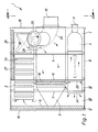
- an exhaust gas purification system in the form of a Diesel emission control system for heavy commercial vehicles three functional elements, namely an exhaust silencer 1 to dampen exhaust gas noise, an SCR catalytic converter 2 for selective Catalytic HC / NOx reduction in addition to upstream Urea injection through a U-shaped urea injection pipe element 4, as well as an exhaust gas particle filter element 3 for the reduction of exhaust gas particles by filtering out soot particles and the like and, if necessary, afterburning or emergency regeneration through a connected diesel burner 10th
- the exhaust silencer 1, the exhaust particle filter element 2 and the catalyst are combined in a common housing and form a structural, functional unit.
- the exhaust silencer 1 is a multi-chamber design with two Reflection chambers and three absorption chambers in common Housing with an oval to rectangular outer jacket in cross section and flat end axial ends 15, 18 executed with the two reflection chambers and the three absorption chambers separated from each other by radial partitions are.
- the housing are in particular cross-chamber in the axial direction and in parallel the SCR catalytic converter 2, the diesel particle filter element 3 and the U-shaped urea injection pipe element 4 provided.
- the SCR catalytic converter 2 is located in the housing at the top, the diesel particulate filter element 3 in the middle and the U-shaped Pipe element 4 below.
- the housing is in particular by four spaced apart radial partitions 5, 6, 7, 8 in five chambers I, II, III, IV, V divided, the first partition 5 between the first chamber I and the second chamber II, the second Partition 6 between the second chamber II and the third Chamber III and the third partition 7 between the third Chamber III and fourth chamber IV through openings for a fixed receptacle of the SCR catalytic converter 2, the diesel particulate filter element 3 and the U-shaped tubular element 4 exhibit.
- the diesel particulate filter element 2 comprises a connecting flange 9, on the outside of the housing the diesel burner 10 is releasably attached, the connecting flange in the Level of the first end face assigned to the first chamber I.
- Axial end 15 of the housing is located and fastened, which the first chamber I together with the first partition 5 limited in the axial direction.
- the diesel particle filter element 2 has second end axial end 18 of the housing one conical cleaning tulip 16 with an openable blind plug 17 at the tapered end of the cleaning tulip 16, which tapered end of the cleaning tulip including blind plugs in the plane of the second end axial end 18 of the housing is located.
- the emission control system is not in operation can after removing the diesel burner and after opening the blind plug of the cleaning tulip the diesel particle filter element by blowing the ash particles backwards into Direction of arrow P can be cleaned.
- the diesel particulate filter element 2 also has a first one Sheath perforation 19 in the area of the third chamber III for a radially outward passage of the exhaust gas.
- the diesel particle filter element 2 also has a radial one Exhaust gas inlet in the area of the first chamber I, with a housing shell side Exhaust gas inlet connector 20 is provided.
- the U-shaped tubular element 4 has a short straight line Pipe section 21 with an axial exhaust gas inlet 22 in the area the third chamber III and a longer straight tube section 23 with an axial exhaust gas outlet 24 in the area of fourth chamber IV and a 180 ° curvature section 25 in Area of the first chamber I, approximately as an extension of the Axis 32 of the longer pipe section 23 a straight in essential urea supply nozzle aligned with the aforementioned axis 32 11 opens into the 180 ° curvature section 25, the at least up to the first axial end 15 of the housing is sufficient and is provided with a mixing nozzle.
- a straight in essential urea supply nozzle aligned with the aforementioned axis 32 11 opens into the 180 ° curvature section 25, the at least up to the first axial end 15 of the housing is sufficient and is provided with a mixing nozzle.
- the short and long straight pipe sections 21, 23 run parallel to each other at the same height of the housing.
- the shorter straight pipe section 21 has a jacket perforation 33 in the area of the second chamber II.
- the SCR catalytic converter 2 comprises on the output side in the area of the first chamber I an axially aligned hollow exhaust outlet housing part 26, while the catalyst core 27 in the area of fourth, third and second chambers IV, III, II is located.
- the exhaust outlet housing part 26 of the SRC catalyst 2 has in Area of the first chamber I a jacket-side exhaust outlet opening 28, to which a 90 ° elbow 29 is connected is that leads to the first axial end 15 of the housing and the Exhaust outlet of exhaust muffler 1 forms.
- the hollow exhaust outlet housing part 26 also has a jacket perforation 30 and an end perforation 31, which facing the first end axial end 15 of the housing is.
- the housing of the catalyst 2 has in the region of the catalyst core 27 stiffening beads 34 and is box-shaped.
- the SCR catalytic converter 2 and the diesel particle filter element 3 and the U-shaped tubular element 4 are in the area of the first and the second chamber I, II in an absorbent material stored and therefore the first and second chambers I, II designed as absorption chambers, while the third and the fourth chamber III, IV are reflection chambers.
- the fifth chamber V already mentioned is an absorption chamber and as such with a muffler absorbent material filled. It is particularly on the second face Axial end 18 of the housing and the fourth chamber IV downstream and axially delimited by the fourth partition 8, which is formed with perforations.
Landscapes
- Engineering & Computer Science (AREA)
- Chemical & Material Sciences (AREA)
- Combustion & Propulsion (AREA)
- Mechanical Engineering (AREA)
- General Engineering & Computer Science (AREA)
- Chemical Kinetics & Catalysis (AREA)
- Health & Medical Sciences (AREA)
- Toxicology (AREA)
- Processes For Solid Components From Exhaust (AREA)
- Exhaust Gas After Treatment (AREA)
Abstract
Description
- Geräuschdämpfung / NOx-Reduktion / Partikel-Reduktion durch Zusammenfassung der drei Funktionselemente in einem einzigen Gehäuse mit minimalem Bauvolumen
- ein Dieselpartikelfilter-Element mit integriertem Diesel-Brenner insbesondere zur Notgeneration bei extrem kalten Betriebszuständen zum Beispiel bei einer kurzen Stadtfahrt
- einen dem Dieselpartikelfilter-Element nachgeschalteten SCR-Katalysator mit vorgeschalteter Harnstoffeinspritzung plus Mischelement
- eine Reinigungsmöglichkeit des Dieselpartikelfilter-Elements durch Ausblasen der Aschepartikel rückwärts über den Brenneranschluß nach Entfernen des Diesel-Brenners und nach Öffnen des Blindstopfens
- eine Einlagerung des Dieselpartikelfilter-Elements und des SCR-Katalysators in das Schalldämpfer-Absorptionsmaterial, wodurch keine Wärmeverluste entstehen bzw. ein sehr schnelles System LIGHT OFF bzw. eine optimale Filterregeneration eingerichtet werden
- eine optimale Harnstoffvermischung durch ein spezielles Mischelement, z.B. eine eingesetzte Strömungsspirale, eine halbkreisförmige Strömungsschleife und/oder durch eine Mischdüse
- Figur 1
- ein kombiniertes Abgasreinigungssystem für ein schweres Diesel-Nutzfahrzeug in Form eines Abgasschalldämpfers in Mehrkammerbauweise mit Katalysator, Dieselpartikelfilter-Element und U-förmigem Harnstoffeinspritz-Rohrelement schematisch in einer vertikalen axialen Schnittansicht,
- Figur 2
- das Abgasreinigungssystem nach Figur 1 in einer schematischen Stirnansicht längs der Linie A-A der Figur 1 unter Weglassung des Diesel-Brenners,
- Figur 3
- das Abgasreinigungssystem nach den Figuren 1 und 2 in einem schematischen Horizontalschnitt längs der Linie B-B der Figur 2, und
- Figur 4
- das U-förmige Harnstoffeinspritz-Rohrelement des Abgasreinigungssystems in einer schematischen Draufsicht ähnlich Figur 3 unter Weglassung des Dieselpartikelfilter-Elements.
Claims (20)
- Abgasreinigungssystem für Kraftfahrzeuge, insbesondere Diesel-Abgasreinigungssystem für mittler bis schwere Nutzfahrzeuge, mit Abgas-Schalldämpfer, Katalysator und Abgaspartikelfilter-Element,
dadurch gekennzeichnet, daß der Abgasschalldämpfer (1), das Abgaspartikelfilter-Element (2) und der Katalysator in einem gemeinsamen Gehäuse zusammengefaßt sind und eine bauliche, funktionelle Einheit bilden. - Abgasreinigungssystem nach Anspruch 1,
dadurch gekennzeichnet, daß der Abgasschalldämpfer (1) in Mehrkammerbauweise mit zumindest einer Reflexionskammer und zumindest einer Absorptionskammer im gemeinsamen Gehäuse mit im Querschnitt ovalem bis rechteckigem Außenmantel und ebenen stirnseitigen Axialenden (15, 18) ausgeführt ist, wobei die Reflexionskammmer(n) und Absorptionskammer(n) durch zumindest eine radiale Trennwand voneinander abgetrennt sind. - Abgasreinigungssystem nach Anspruch 1 oder 2,
dadurch gekennzeichnet, daß der Katalysator ein SCR-Katalysator (2) für eine selektive katalytische Reduktion der Abgas-Schadstoffe ist. - Abgasreinigungssystem nach einem der Ansprüche 1 bis 3,
dadurch gekennzeichnet, daß das Abgaspartikelfilter-Element ein Dieselpartikelfilter-Element (3) ist. - Abgasreinigungssystem nach Anspruch 4,
dadurch gekennzeichnet, daß im Gehäuse in Axialrichtung kammerübergreifend und im wesentlichen parallel zueinander der SCR-Katalysator (2), das Dieselpartikelfilter-Element (3) und ein U-förmiges Harnstoffeinspritz-Rohrelement (4) vorgesehen sind. - Abgasreinigungssystem nach Anspruch 5,
dadurch gekennzeichnet, daß das Gehäuse durch zumindest drei voneinander beabstandete radiale Trennwände (5, 6, 7, 8) in zumindest vier Kammern (I, II, III, IV, V) unterteilt ist, wobei die erste Trennwand (5) zwischen der ersten Kammer (I) und der zweiten Kammer (II), die zweite Trennwand (6) zwischen der zweiten Kammer (II) und der dritten Kammer (III) sowie die dritte Trennwand (7) zwischen der dritten Kammer (III) und der vierten Kammer (IV) Durchgangsöffnungen für eine befestigte Aufnahme des SCR-Katalysators (2), des Dieselpartikelfilter-Elements (3) sowie des U-förmigen Rohrelements (4) aufweisen. - Abgasreinigungssystem nach Anspruch 5 oder 6,
dadurch gekennzeichnet, daß das Dieselpartikelfilter-Element (2) einen Anschlußflansch (9) aufweist, an welchem gehäuseaußenseitig ein Diesel-Brenner (10) lösbar befestigt ist, wobei der Anschlußflansch in der Ebene des der ersten Kammer (I) zugeordneten ersten stirnseitigen Axialendes (15) des Gehäuses gelegen und befestigt ist, welches die erste Kammer (I) zusammen mit der ersten Trennwand (5) in Axialrichtung begrenzt. - Abgasreinigungssystem nach einem der Ansprüche 4 bis 7,
dadurch gekennzeichnet, daß das Dieselpartikelfilter-Element (2) im Bereich des anderen, zweiten stirnseitigen Axialendes (18) des Gehäuses eine konische Reinigungstulpe (16) mit einem öffenbaren Blindstopfen (17) am verjüngten Ende der Reinigungstulpe (16) aufweist, wobei das verjüngte Ende der Reinigungstulpe einschießlich Blindstopfen in der Ebene des zweiten stirnseitigen Axialendes (18) des Gehäuses gelegen ist. - Abgasreinigungssystem nach einem der Ansprüche 4 bis 8,
dadurch gekennzeichnet, daß das Dieselpartikelfilter-Element (2) eine erste Mantelperforation (19) im Bereich der dritten Kammer (III) für einen radial nach außen gerichteten Durchtritt des Abgases besitzt. - Abgasreinigungssystem nach einem der Ansprüche 4 bis 9,
dadurch gekennzeichnet, daß das Dieselpartikelfilter-Element (2) einen radialen Abgaseintritt im Bereich der ersten Kammer (I) besitzt, wobei ein gehäusemantelseitiger Abgaseinlaßstutzen (20) vorgesehen ist. - Abgasreinigungssystem nach einem der Ansprüche 5 bis 10,
dadurch gekennzeichnet, daß das U-förmige Rohrelement (4) einen kurzen geradlinigen Rohrabschnitt (21) mit einem axialen Abgaseingang (22) im Bereich der dritten Kammer (III) und eine längeren geradlinigen Rohrabschnitt (23) mit einem axialen Abgasausgang (24) im Bereich der vierten Kammer (IV) sowie einen 180°-Krümmungsabschnitt (25) im Bereich der ersten Kammer (I) aufweist, wobei etwa in Verlängerung der Achse (32) des längeren Rohrabschnitt (23) ein geradliniger im wesentlichen zur vorgenannten Achse (32) ausgerichteter Harnstoffzufuhrstutzen (11) in den 180°-Krümmungsabschnitt (25) einmündet, der zumindest bis zum ersten Axialende (15) des Gehäuses reicht. - Abgasreinigungssystem nach Anspruch 11,
dadurch gekennzeichnet, daß der kurze und der lange geradlinige Rohrabschnitt (21, 23) parallel zueinander in gleicher Höhe des Gehäuses verlaufen. - Abgasreinigungssystem nach Anspruch 11 oder 12,
dadurch gekennzeichnet, daß der kürzere geradlinige Rohrabschnitt (21) eine Mantelperforation (33) im Bereich der zweiten Kammer (II) besitzt. - Abgasreinigungssystem nach einem der Ansprüche 3 bis 13,
dadurch gekennzeichnet, daß der SCR-Katalysator (2) ausgangsseitig im Bereich der ersten Kammer (I) ein axial ausgerichtetes hohles Abgasauslaß-Gehäuseteil (26) besitzt, während der Katalysatorkern (27) im Bereich der vierten, dritten und zweiten Kammer (IV, III, II) gelegen ist. - Abgasreinigungssystem nach Anspruch 14,
dadurch gekennzeichnet, daß das Abgasauslaß-Gehäuseteil (26) des SRC-Katalysators (2) im Bereich der ersten Kammer (I) eine mantelseitige Abgasauslaß-Öffnung (28) besitzt, an welche ein Rohrkrümmer (29) angeschlossen ist, der zum ersten Axialende (15) des Gehäuses führt und den Abgasausgang des Abgas-Schalldämpfers (1) bildet. - Abgasreinigungssystem nach Anspruch 14 oder 15,
dadurch gekennzeichnet,
der hohle Abgasauslaß-Gehäuseteil (26) eine Mantelperforation (30) und eine stirnseitige Perforation (31) besitzt. - Abgasreinigungssystem nach einem der Ansprüche 14 bis 16,
dadurch gekennzeichnet, daß das Gehäuse des Katalysatorkerns (27) Versteifungssicken (34) aufweist. - Abgasreinigungssystem nach einem der Ansprüche 3 bis 17,
dadurch gekennzeichnet, daß der SCR-Katalysator (2) ein kastenförmiges Gehäuse aufweist. - Abgasreinigungssystem nach einem der Ansprüche 5 bis 18,
dadurch gekennzeichnet, daß der SCR-Katalysator (2) und das Dieselpartikelfilter-Element (3) sowie das U-förmige Rohrelement (4) im Bereich der ersten und der zweiten Kammer (I, II) in einem Absorptionsmaterial eingelagert und mithin die erste und die zweite Kammer (I, II) als Absorptionskammern ausgebildet sind, während der dritte und die vierte Kammer (III, IV) Reflexionskammern sind. - Abgasreinigungssystem nach einem der Ansprüche 6 bis 19,
dadurch gekennzeichnet, daß am zweiten stirnseitigen Axialende (18) des Gehäuses eine der vierten Kammer (IV) nachgeordnete als Absorptionskammer ausgebildete, Schalldämpfer-Absorptionsmaterial enthaltende fünfte Kammer (V) vorgesehen ist, wobei die vierte Trennwand (8) Perforationen aufweist.
Applications Claiming Priority (2)
| Application Number | Priority Date | Filing Date | Title |
|---|---|---|---|
| DE10042542 | 2000-08-30 | ||
| DE10042542A DE10042542A1 (de) | 2000-08-30 | 2000-08-30 | Abgasreinigungssystem für Kraftfahrzeuge, insbesondere Diesel-Nutzfahrzeuge |
Publications (3)
| Publication Number | Publication Date |
|---|---|
| EP1184543A2 true EP1184543A2 (de) | 2002-03-06 |
| EP1184543A3 EP1184543A3 (de) | 2004-01-07 |
| EP1184543B1 EP1184543B1 (de) | 2007-09-12 |
Family
ID=7654280
Family Applications (1)
| Application Number | Title | Priority Date | Filing Date |
|---|---|---|---|
| EP01115336A Expired - Lifetime EP1184543B1 (de) | 2000-08-30 | 2001-06-26 | Abgasreinigungssystem für Kraftfahrzeuge, insbesondere Diesel-Nutzfahrzeuge |
Country Status (3)
| Country | Link |
|---|---|
| US (2) | US6729127B2 (de) |
| EP (1) | EP1184543B1 (de) |
| DE (2) | DE10042542A1 (de) |
Cited By (3)
| Publication number | Priority date | Publication date | Assignee | Title |
|---|---|---|---|---|
| EP1728984A3 (de) * | 2005-05-30 | 2006-12-20 | J. Eberspächer GmbH & Co. KG | Abgasanlage |
| FR2986826A1 (fr) * | 2012-02-09 | 2013-08-16 | Peugeot Citroen Automobiles Sa | Dispositif de traitement des gaz d'echappement d'un moteur a combustion et vehicule automobile associe |
| EP2233708B1 (de) | 2009-03-26 | 2016-07-27 | Eberspächer Exhaust Technology GmbH & Co. KG | Abgasbehandlungseinrichtung |
Families Citing this family (60)
| Publication number | Priority date | Publication date | Assignee | Title |
|---|---|---|---|---|
| DE20303775U1 (de) | 2003-03-07 | 2004-07-29 | Purem Abgassysteme Gmbh & Co. Kg | Abgas-Partikelfilterelement |
| DE10316802A1 (de) * | 2003-04-11 | 2004-10-21 | Man Nutzfahrzeuge Ag | Kombinierte Abgasnachbehandlungs-/Schalldämpfungsvorrichtung im Abgasstrang einer Brennkraftmaschine |
| DE10316799A1 (de) * | 2003-04-11 | 2004-10-28 | Man Nutzfahrzeuge Ag | Kombinierte Abgasnachbehandlungs-/Schalldämpfungsvorrichtung im Abgasstrang einer Brennkraftmaschine |
| DE10335265B4 (de) * | 2003-08-01 | 2014-02-27 | Man Truck & Bus Ag | Kraftfahrzeug mit spezieller Anordnung eines Kraftstofftanks, Vorschalldämpfers und Reduktionsmitteltanks |
| DE10356000B4 (de) * | 2003-11-27 | 2006-01-12 | J. Eberspächer GmbH & Co. KG | Schalldämpfer mit integriertem Katalysator |
| US7188469B2 (en) * | 2003-12-29 | 2007-03-13 | Delphi Technologies, Inc. | Exhaust system and methods of reducing contaminants in an exhaust stream |
| JP3715981B2 (ja) * | 2004-03-25 | 2005-11-16 | 日産ディーゼル工業株式会社 | 排気浄化機能付き消音装置 |
| DE102004043931B4 (de) | 2004-09-11 | 2014-08-21 | Eberspächer Exhaust Technology GmbH & Co. KG | Abgasnachbehandlungseinrichtung |
| DE102005002289B4 (de) | 2005-01-17 | 2007-04-19 | J. Eberspächer GmbH & Co. KG | Abgasbehandlungssystem |
| US7552587B2 (en) * | 2005-02-03 | 2009-06-30 | Basf Catalysts Llc | Deflector plate to enhance fluid stream contact with a catalyst |
| US20060218904A1 (en) * | 2005-03-08 | 2006-10-05 | Brady William J | Diesel emissions control system and method |
| US20060201145A1 (en) * | 2005-03-08 | 2006-09-14 | Brady William J | Low emissions diesel system and method |
| BRPI0621003A2 (pt) * | 2006-01-24 | 2011-11-29 | Volvo Lastvagnar Ab | sistema de pós-tratamento de gás de exaustão |
| US20070178025A1 (en) * | 2006-01-31 | 2007-08-02 | Opris Cornelius N | Exhaust treatment system |
| US7717205B2 (en) * | 2006-11-28 | 2010-05-18 | Caterpillar Inc. | Engine hood assembly enclosure with exhaust aftertreatment device integrated therein, and machine using same |
| US20080141662A1 (en) * | 2006-12-14 | 2008-06-19 | Markus Schuster | Fluid injecting and mixing systems for exhaust after-treatment devices |
| JP4286888B2 (ja) * | 2007-09-28 | 2009-07-01 | 日産ディーゼル工業株式会社 | 排気浄化装置 |
| JP4286887B2 (ja) * | 2007-09-28 | 2009-07-01 | 日産ディーゼル工業株式会社 | 排気浄化装置 |
| DE102007062663A1 (de) * | 2007-12-24 | 2009-06-25 | J. Eberspächer GmbH & Co. KG | Schiebesitz sowie Rohranordnung und Abgasbehandlungseinrichtung |
| DE102008022081A1 (de) * | 2008-05-05 | 2009-11-12 | J. Eberspächer GmbH & Co. KG | Abgasbehandlungseinrichtung |
| US8341949B2 (en) * | 2008-05-30 | 2013-01-01 | Caterpillar Inc. | After-treatment system |
| DE102008035562A1 (de) * | 2008-07-30 | 2010-02-04 | Emitec Gesellschaft Für Emissionstechnologie Mbh | Abgasreinigungssystem für Dieselmotoren von Nutzkraftfahrzeugen |
| US20100186394A1 (en) * | 2009-01-26 | 2010-07-29 | Caterpillar Inc. | Exhaust gas after treatment assembly |
| US20100186381A1 (en) * | 2009-01-26 | 2010-07-29 | Caterpillar Inc | Exhaust system thermal enclosure |
| US8460610B2 (en) * | 2009-12-22 | 2013-06-11 | Caterpillar Inc. | Canister aftertreatment module |
| US8596049B2 (en) * | 2009-12-22 | 2013-12-03 | Caterpillar Inc. | Exhaust system having an aftertreatment module |
| DE112010005012B4 (de) | 2009-12-23 | 2023-02-16 | Caterpillar Inc. | Abgasnachbehandlungssystem |
| US8635861B2 (en) | 2009-12-23 | 2014-01-28 | Caterpillar Inc. | Exhaust aftertreatment system |
| DE102010015271A1 (de) | 2010-04-15 | 2011-10-20 | J. Eberspächer GmbH & Co. KG | Abgasbehandlungseinrichtung |
| DE102010034743A1 (de) | 2010-08-19 | 2012-02-23 | J. Eberspächer GmbH & Co. KG | Abgasreinigungsvorrichtung, Abgasanlage, Ausbauverfahren |
| US8609030B2 (en) | 2011-03-04 | 2013-12-17 | Tenneco Automotive Operating Company Inc. | Exhaust aftertreatment device with integrated shell and baffle |
| US8776509B2 (en) | 2011-03-09 | 2014-07-15 | Tenneco Automotive Operating Company Inc. | Tri-flow exhaust treatment device with reductant mixing tube |
| US8959900B2 (en) * | 2012-03-26 | 2015-02-24 | GM Global Technology Operations LLC | Exhaust aftertreatment system for internal combustion engine |
| CN103573335A (zh) * | 2012-07-31 | 2014-02-12 | 东莞市旗丰消声器有限公司 | 带前后消声器的盒形摩托车消声器 |
| US8850801B2 (en) * | 2013-01-25 | 2014-10-07 | Caterpillar Inc. | Catalytic converter and muffler |
| CN103133088B (zh) * | 2013-03-20 | 2014-10-22 | 中国第一汽车股份有限公司 | 方形后处理器总成 |
| BR112016007343A2 (pt) * | 2013-10-03 | 2017-08-01 | Umicore Ag & Co Kg | sistema de tratamento de escape, e processo para redução de poluentes nocivos |
| WO2016109320A1 (en) * | 2014-12-31 | 2016-07-07 | Cummins Emission Solutions, Inc. | Single module integrated aftertreatment module |
| CN112901319B (zh) | 2014-12-31 | 2022-12-16 | 康明斯排放处理公司 | 紧密联接的单模块后处理系统 |
| GB2548040B (en) | 2014-12-31 | 2020-11-25 | Cummins Emission Solutions Inc | Compact side inlet and outlet exhaust aftertreatment system |
| US10071626B2 (en) | 2015-04-28 | 2018-09-11 | Cnh Industrial America Llc | Exhaust after-treatment mounting arrangement |
| US10267199B2 (en) | 2015-07-28 | 2019-04-23 | Cummins Emission Solutions Inc. | Angled sensor mount for use with a single module aftertreatment system or the like |
| USD794100S1 (en) | 2015-09-28 | 2017-08-08 | Cummins Emission Solutions Inc. | Aftertreatment system housing |
| US11136910B2 (en) | 2017-06-06 | 2021-10-05 | Cummins Emission Solutions Inc. | Systems and methods for mixing exhaust gases and reductant in an aftertreatment system |
| WO2020009694A1 (en) * | 2018-07-03 | 2020-01-09 | Cummins Emission Solutions Inc. | Body mixing decomposition reactor |
| CN109488423B (zh) * | 2018-12-27 | 2024-03-15 | 东风商用车有限公司 | 一种汽车尾气处理生氨系统 |
| US12503969B2 (en) | 2019-12-03 | 2025-12-23 | Cummins Emission Solutions Inc. | Reductant delivery system for exhaust gas aftertreatment system |
| CN120132644A (zh) | 2020-02-27 | 2025-06-13 | 康明斯排放处理公司 | 用于后处理系统中的混合器 |
| GB2631666A (en) * | 2020-10-22 | 2025-01-08 | Cummins Emission Solutions Inc | Exhaust gas aftertreatment system |
| CN112664304A (zh) * | 2020-12-14 | 2021-04-16 | 广西玉柴机器股份有限公司 | 一种带三级后处理的国六发动机结构 |
| CN112648052B (zh) * | 2020-12-25 | 2022-03-25 | 一汽解放汽车有限公司 | 一种尿素罐保压控制系统及其保养方法 |
| DE102021000152A1 (de) | 2021-01-15 | 2022-07-21 | Mercedes-Benz Group AG | Abgasanlage für eine Verbrennungskraftmaschine eines Kraftfahrzeugs |
| GB2618011B (en) | 2021-02-02 | 2025-02-26 | Cummins Emission Solutions Inc | Exhaust gas aftertreatment systems |
| US12123337B2 (en) | 2021-03-18 | 2024-10-22 | Cummins Emission Solutions Inc. | Aftertreatment systems |
| CN112901312B (zh) * | 2021-03-27 | 2022-03-11 | 扬州工业职业技术学院 | 一种柴油机排气净化处理装置与方法 |
| CN117396668A (zh) | 2021-07-27 | 2024-01-12 | 康明斯排放处理公司 | 废气后处理系统 |
| DE102021121653B3 (de) * | 2021-08-20 | 2022-12-15 | Tenneco Gmbh | Abgasbehandlungseinheit |
| CN119643152A (zh) | 2021-08-23 | 2025-03-18 | 康明斯排放处理公司 | 用于后处理系统的出口取样系统 |
| USD1042544S1 (en) | 2022-04-21 | 2024-09-17 | Cummins Emission Solutions Inc. | Aftertreatment system |
| USD1042545S1 (en) | 2022-04-21 | 2024-09-17 | Cummins Emission Solutions Inc. | Aftertreatment system |
Family Cites Families (28)
| Publication number | Priority date | Publication date | Assignee | Title |
|---|---|---|---|---|
| US2958389A (en) * | 1957-04-08 | 1960-11-01 | Oldberg Mfg Company | Silencer or muffler |
| US3082840A (en) * | 1960-07-11 | 1963-03-26 | Reindl Joseph | Muffler |
| US3712030A (en) * | 1970-09-14 | 1973-01-23 | J Priest | Exhaust depurator |
| GB1446553A (en) * | 1972-12-06 | 1976-08-18 | Nicoll W L G | Mufflers |
| US3822531A (en) * | 1973-02-27 | 1974-07-09 | Ppg Industries Inc | Device for agglomerating and separating particulates from a gas |
| US3960528A (en) * | 1973-03-08 | 1976-06-01 | E. I. Du Pont De Nemours And Company | Muffler particulate trap for internal combustion engines |
| US4074975A (en) * | 1973-05-07 | 1978-02-21 | Nissan Motor Company, Limited | Combination exhaust-gas cleaner and muffler for an automobile engine |
| US4111278A (en) * | 1977-02-09 | 1978-09-05 | Copeland Corporation | Discharge muffler |
| FR2550820B1 (fr) * | 1983-08-18 | 1987-08-21 | Jourdan Charles | Dispositif d'echappement pour moteur a combustion interne |
| DE3516442A1 (de) * | 1985-05-08 | 1986-11-13 | Jörg Prof. Dipl.-Ing.(FH) 7072 Heubach Linser | Schalldaempfer |
| DE3538107A1 (de) * | 1985-10-26 | 1987-04-30 | Man Technologie Gmbh | Filter zur reinigung von abgasen |
| CA1262869A (en) * | 1988-06-23 | 1989-11-14 | Glen Knight | Combined muffler and catalytic converter exhaust unit |
| EP0468955A1 (de) * | 1989-04-17 | 1992-02-05 | Emitec Gesellschaft für Emissionstechnologie mbH | Dieselrussfilter mit zusätzlicher einrichtung zur reduktion von stickoxyden und/oder oxydation von kohlenmonoxyd |
| US5052178A (en) * | 1989-08-08 | 1991-10-01 | Cummins Engine Company, Inc. | Unitary hybrid exhaust system and method for reducing particulate emmissions from internal combustion engines |
| US5373119A (en) * | 1990-11-23 | 1994-12-13 | Kioritz Corporation | Exhaust muffler for internal combustion engine |
| US5139107A (en) * | 1990-12-11 | 1992-08-18 | Kioritz Corporation | Exhaust muffler for internal combustion engines |
| DE9217940U1 (de) * | 1992-03-24 | 1993-03-18 | H.J.S. Fahrzeugteile-Fabrik Gmbh & Co, 5750 Menden | Abgasanlage für Dieselkraftfahrzeuge |
| US5376341A (en) * | 1992-07-24 | 1994-12-27 | Corning Incorporated | Catalytic converter for motorcycles |
| US5434374A (en) * | 1993-12-01 | 1995-07-18 | Hsueh; Tien-Chu | Detachable filter and muffler device |
| AU6295696A (en) * | 1995-06-30 | 1997-02-26 | Antoine Poppe | Filter for exhaust gases of a gasoline engine, respectively a diesel engine |
| DE19611133A1 (de) * | 1996-03-21 | 1997-09-25 | Eberspaecher J | Schalldämpfer-Anordnung |
| US5783782A (en) * | 1996-10-29 | 1998-07-21 | Tenneco Automotive Inc. | Multi-chamber muffler with selective sound absorbent material placement |
| JP3830218B2 (ja) * | 1997-01-31 | 2006-10-04 | 株式会社共立 | 2サイクル内燃エンジン用マフラー |
| US5984045A (en) * | 1997-02-14 | 1999-11-16 | Nissan Motor Co., Ltd. | Engine exhaust noise suppressor |
| EP1060328B1 (de) * | 1997-12-30 | 2002-09-11 | Silentor Holding A/S | Schalldämpfer |
| DE19802624A1 (de) * | 1998-01-24 | 1999-07-29 | Eberspaecher J Gmbh & Co | Abgasschalldämpfer für Verbrennungsmotoren |
| DE19807935C1 (de) * | 1998-02-25 | 1999-08-26 | Siemens Ag | Vorrichtung zur Reduzierung des NO¶x¶-Gehaltes im Abgas einer Brennkraftmaschine |
| US5959263A (en) * | 1998-05-07 | 1999-09-28 | Biggs Manufacturing, Inc. | Bypass muffler |
-
2000
- 2000-08-30 DE DE10042542A patent/DE10042542A1/de not_active Withdrawn
-
2001
- 2001-06-26 EP EP01115336A patent/EP1184543B1/de not_active Expired - Lifetime
- 2001-06-26 DE DE50112993T patent/DE50112993D1/de not_active Expired - Lifetime
- 2001-08-15 US US09/930,555 patent/US6729127B2/en not_active Expired - Lifetime
-
2003
- 2003-06-18 US US10/464,534 patent/US20030221424A1/en not_active Abandoned
Cited By (3)
| Publication number | Priority date | Publication date | Assignee | Title |
|---|---|---|---|---|
| EP1728984A3 (de) * | 2005-05-30 | 2006-12-20 | J. Eberspächer GmbH & Co. KG | Abgasanlage |
| EP2233708B1 (de) | 2009-03-26 | 2016-07-27 | Eberspächer Exhaust Technology GmbH & Co. KG | Abgasbehandlungseinrichtung |
| FR2986826A1 (fr) * | 2012-02-09 | 2013-08-16 | Peugeot Citroen Automobiles Sa | Dispositif de traitement des gaz d'echappement d'un moteur a combustion et vehicule automobile associe |
Also Published As
| Publication number | Publication date |
|---|---|
| US20020023435A1 (en) | 2002-02-28 |
| DE50112993D1 (de) | 2007-10-25 |
| DE10042542A1 (de) | 2002-03-14 |
| US6729127B2 (en) | 2004-05-04 |
| EP1184543A3 (de) | 2004-01-07 |
| EP1184543B1 (de) | 2007-09-12 |
| US20030221424A1 (en) | 2003-12-04 |
Similar Documents
| Publication | Publication Date | Title |
|---|---|---|
| EP1184543B1 (de) | Abgasreinigungssystem für Kraftfahrzeuge, insbesondere Diesel-Nutzfahrzeuge | |
| DE69704351T2 (de) | Schalldämpfer | |
| EP1857651B1 (de) | Abgasnachbehandlungseinrichtung für eine Brennkraftmaschine | |
| EP1728984B2 (de) | Abgasanlage | |
| DE102005002289B4 (de) | Abgasbehandlungssystem | |
| DE69900548T2 (de) | Vorrichtung zur reduktion von nox in abgasen | |
| EP1556587B1 (de) | Abgasnachbehandlungssystem, insbesondere für einen dieselmotor | |
| EP1108122B1 (de) | Einrichtung zur katalytischen abgasreinigung | |
| DE60302555T2 (de) | Abgasstrang einer brennkraftmaschine und kraftfahrzeug aufweisend ein solcher abgasstrang | |
| EP1379322B2 (de) | Abgassystem | |
| EP1260682B1 (de) | Abgasstrang einer Brennkraftmaschine, insbesondere Dieselmotor eines Nutzfahrzeuges wie Lastkraftwagen oder Omnibus, mit integrierten Abgasnachbehandlungs- und Schalldämpfungsvorrichtungen | |
| EP1536113A2 (de) | Schalldämpfer mit integriertem Katalysator | |
| EP1179125B1 (de) | Vorrichtung zum reduzieren von schädlichen bestandteilen im abgas einer brennkraftmaschine, insbesondere einer diesel-brennkraftmaschine | |
| DE202007010435U1 (de) | Abgasanlage für Nutzfahrzeuge | |
| EP1475522B1 (de) | Kombinierte Abgasnachbehandlungs-/Schalldämpfungsvorrichtung im Abgasstrang einer Brennkraftmaschine | |
| DE112014006379T5 (de) | Plenumkammer für eine Abgasanlage | |
| EP0556846A1 (de) | Abgasschalldämpfer für Dieselmotoren insbesondere von Nutzfahrzeugen | |
| EP3704360B1 (de) | Abgasanlage zur kompakten und effizienten nachbehandlung und schalldämpfung des abgases | |
| EP2166203A1 (de) | Vorrichtung zur Reinigung eines Abgasstroms einer Brennkraftmaschine eines Kraftfahrzeuges, insbesondere eines Nutzfahrzeuges | |
| DE19952428A1 (de) | Verfahren und Vorrichtung zur kombinierten katalytischen NOx-Reduktion und Schalldämpfung von Abgas im Abgasstrang einer Brennkraftmaschine | |
| DE60214748T2 (de) | In einem abgassystem für einen verbrennungsmotor angeordnetes gehäuse | |
| DE10329436B4 (de) | Abgasreinigungssystem für eine Brennkraftmaschine | |
| EP1258606A2 (de) | Kombinierte Abgasnachbehandlungs-/Schalldämpfungsvorrichtung im Abgasstrang einer Brennkraftmaschine | |
| EP1262640B1 (de) | Abgasstrang einer Brennkraftmaschine, insbesondere Dieselmotor eines Nutzfahrzeuges wie Lastkraftwagen oder Omnibus, mit integrierten Abgasnachbehandlungs- und Schalldämpfungsvorrichtungen | |
| EP1688597A2 (de) | Abgasreinigungsvorrichtung |
Legal Events
| Date | Code | Title | Description |
|---|---|---|---|
| PUAI | Public reference made under article 153(3) epc to a published international application that has entered the european phase |
Free format text: ORIGINAL CODE: 0009012 |
|
| AK | Designated contracting states |
Kind code of ref document: A2 Designated state(s): AT BE CH CY DE DK ES FI FR GB GR IE IT LI LU MC NL PT SE TR |
|
| AX | Request for extension of the european patent |
Free format text: AL;LT;LV;MK;RO;SI |
|
| RAP1 | Party data changed (applicant data changed or rights of an application transferred) |
Owner name: J. EBERSPAECHER GMBH & CO. KG |
|
| PUAL | Search report despatched |
Free format text: ORIGINAL CODE: 0009013 |
|
| AK | Designated contracting states |
Kind code of ref document: A3 Designated state(s): AT BE CH CY DE DK ES FI FR GB GR IE IT LI LU MC NL PT SE TR |
|
| AX | Request for extension of the european patent |
Extension state: AL LT LV MK RO SI |
|
| 17P | Request for examination filed |
Effective date: 20040707 |
|
| AKX | Designation fees paid |
Designated state(s): DE FR GB IT SE |
|
| GRAP | Despatch of communication of intention to grant a patent |
Free format text: ORIGINAL CODE: EPIDOSNIGR1 |
|
| GRAC | Information related to communication of intention to grant a patent modified |
Free format text: ORIGINAL CODE: EPIDOSCIGR1 |
|
| 17Q | First examination report despatched |
Effective date: 20060309 |
|
| GRAS | Grant fee paid |
Free format text: ORIGINAL CODE: EPIDOSNIGR3 |
|
| GRAA | (expected) grant |
Free format text: ORIGINAL CODE: 0009210 |
|
| AK | Designated contracting states |
Kind code of ref document: B1 Designated state(s): DE FR GB IT SE |
|
| REG | Reference to a national code |
Ref country code: GB Ref legal event code: FG4D Free format text: NOT ENGLISH |
|
| REF | Corresponds to: |
Ref document number: 50112993 Country of ref document: DE Date of ref document: 20071025 Kind code of ref document: P |
|
| REG | Reference to a national code |
Ref country code: SE Ref legal event code: TRGR |
|
| GBT | Gb: translation of ep patent filed (gb section 77(6)(a)/1977) |
Effective date: 20071108 |
|
| ET | Fr: translation filed | ||
| PLBE | No opposition filed within time limit |
Free format text: ORIGINAL CODE: 0009261 |
|
| STAA | Information on the status of an ep patent application or granted ep patent |
Free format text: STATUS: NO OPPOSITION FILED WITHIN TIME LIMIT |
|
| 26N | No opposition filed |
Effective date: 20080613 |
|
| REG | Reference to a national code |
Ref country code: FR Ref legal event code: PLFP Year of fee payment: 15 |
|
| REG | Reference to a national code |
Ref country code: FR Ref legal event code: PLFP Year of fee payment: 16 |
|
| REG | Reference to a national code |
Ref country code: FR Ref legal event code: PLFP Year of fee payment: 17 |
|
| REG | Reference to a national code |
Ref country code: FR Ref legal event code: PLFP Year of fee payment: 18 |
|
| PGFP | Annual fee paid to national office [announced via postgrant information from national office to epo] |
Ref country code: SK Payment date: 20180712 Year of fee payment: 15 |
|
| PG25 | Lapsed in a contracting state [announced via postgrant information from national office to epo] |
Ref country code: IT Free format text: LAPSE BECAUSE OF NON-PAYMENT OF DUE FEES Effective date: 20190626 |
|
| PGFP | Annual fee paid to national office [announced via postgrant information from national office to epo] |
Ref country code: DE Payment date: 20200623 Year of fee payment: 20 Ref country code: FR Payment date: 20200623 Year of fee payment: 20 |
|
| PGFP | Annual fee paid to national office [announced via postgrant information from national office to epo] |
Ref country code: SE Payment date: 20200625 Year of fee payment: 20 Ref country code: GB Payment date: 20200625 Year of fee payment: 20 |
|
| REG | Reference to a national code |
Ref country code: DE Ref legal event code: R071 Ref document number: 50112993 Country of ref document: DE |
|
| REG | Reference to a national code |
Ref country code: GB Ref legal event code: PE20 Expiry date: 20210625 |
|
| REG | Reference to a national code |
Ref country code: SE Ref legal event code: EUG |
|
| PG25 | Lapsed in a contracting state [announced via postgrant information from national office to epo] |
Ref country code: GB Free format text: LAPSE BECAUSE OF EXPIRATION OF PROTECTION Effective date: 20210625 |