EP1184115A1 - Gesteinsbohrer - Google Patents
Gesteinsbohrer Download PDFInfo
- Publication number
- EP1184115A1 EP1184115A1 EP01810807A EP01810807A EP1184115A1 EP 1184115 A1 EP1184115 A1 EP 1184115A1 EP 01810807 A EP01810807 A EP 01810807A EP 01810807 A EP01810807 A EP 01810807A EP 1184115 A1 EP1184115 A1 EP 1184115A1
- Authority
- EP
- European Patent Office
- Prior art keywords
- hard material
- rock drill
- drill according
- tool
- material insert
- Prior art date
- Legal status (The legal status is an assumption and is not a legal conclusion. Google has not performed a legal analysis and makes no representation as to the accuracy of the status listed.)
- Withdrawn
Links
Images

Classifications
-
- B—PERFORMING OPERATIONS; TRANSPORTING
- B23—MACHINE TOOLS; METAL-WORKING NOT OTHERWISE PROVIDED FOR
- B23B—TURNING; BORING
- B23B51/00—Tools for drilling machines
- B23B51/02—Twist drills
-
- E—FIXED CONSTRUCTIONS
- E21—EARTH OR ROCK DRILLING; MINING
- E21B—EARTH OR ROCK DRILLING; OBTAINING OIL, GAS, WATER, SOLUBLE OR MELTABLE MATERIALS OR A SLURRY OF MINERALS FROM WELLS
- E21B10/00—Drill bits
- E21B10/44—Bits with helical conveying portion, e.g. screw type bits; Augers with leading portion or with detachable parts
- E21B10/445—Bits with helical conveying portion, e.g. screw type bits; Augers with leading portion or with detachable parts percussion type, e.g. for masonry
-
- B—PERFORMING OPERATIONS; TRANSPORTING
- B23—MACHINE TOOLS; METAL-WORKING NOT OTHERWISE PROVIDED FOR
- B23B—TURNING; BORING
- B23B2226/00—Materials of tools or workpieces not comprising a metal
- B23B2226/75—Stone, rock or concrete
-
- B—PERFORMING OPERATIONS; TRANSPORTING
- B23—MACHINE TOOLS; METAL-WORKING NOT OTHERWISE PROVIDED FOR
- B23B—TURNING; BORING
- B23B2228/00—Properties of materials of tools or workpieces, materials of tools or workpieces applied in a specific manner
- B23B2228/56—Two phase materials
-
- B—PERFORMING OPERATIONS; TRANSPORTING
- B23—MACHINE TOOLS; METAL-WORKING NOT OTHERWISE PROVIDED FOR
- B23B—TURNING; BORING
- B23B2251/00—Details of tools for drilling machines
- B23B2251/14—Configuration of the cutting part, i.e. the main cutting edges
Definitions
- the invention relates to a rock drill for the abrasive processing of rock or rock-like material by at least partially with respect to the drill axis rotating and striking movement with a helical spiral and one Hard material insert.
- Usual rock drills have a hard plate or a solid head, Hard material insert, which is fastened in the tool head, to which a shank is attached connects to a helical spiral passage, which is ultimately in one Insertion area for receiving in a tool device ends.
- both the main cutting edges and the secondary cutting edges have circumferentially arranged, blunt guide edges which guide the tool head by they slide past the inner casing of the borehole.
- Such friction-causing leading edges are dimensioned as small as possible.
- a rock drill has a hard material head with two main and two secondary cutting edges, the circumferential, each of which runs parallel to the drill axis, blunt guide edges open into the four-course spiral aisles.
- the disadvantage is the only small, leading sector of the sector with the leading edge per cutting edge Cross-sectional plane.
- a twist drill for machining material has one Tool head with two hard material plates, which form the main cutting edges and their circumferentially arranged, blunt leading edges in the four-course spiral aisles open out.
- the individual hardboard, the leading edges of which are the helical gears Continue smoothly, inclined to the drill axis and only with one each Side facing the drilling direction attached to the tool head, whereby the other, free side surface in the end area of the spiral grooves, which is subject to high stress is integrated.
- An axially striking stress of such a hard material insert would stress its attachment with the tool head on train and thus after fail in a short time.
- the object of the invention is to implement a rock drill with a large management sector area at the cross-sectional level.
- the attachment with the rest of the tool at least partially rotating and striking stress is designed, at least one leading edge a hard material insert at an acute angle to the direction of the tool axis arranged.
- the size of the leading edge is increased without increasing the rubbing side surface Leading sector area in the cross-sectional plane approximately according to the sine of the angle increased.
- the hard material insert is only attached against the drilling direction or surfaces of the hard material insert oriented perpendicular to it and thus exclusively on Pressure and shear stress, which do not fail under impact stress.
- leading edge advantageously continues the helical course smoothly, which increases the conveying resistance of the removed material in the spiral groove is reduced.
- the rock drill has a solid head, which with its surfaces facing away from or perpendicular to the drilling direction is attached.
- the leading edge of at least one hard material insert forms with the direction the tool axis from an acute angle.
- the rock drill has a hard material plate, which with their surfaces facing away from or perpendicular to the drilling direction is attached.
- the leading edge of at least one hard material insert forms with the direction the tool axis from an acute angle.
- a hardboard with only one, facing away from the drilling direction, is advantageous Side surface attached to the rest of the tool, further advantageously the other, free Side surface smoothly integrated in the end area of the spiral grooves, which is subject to high abrasive stress is.
- the solid hard material head which is no longer prismatic due to the inclined leading edge advantageously manufactured by injection molding.
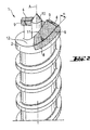
- FIG. 1 shows a rock drill 1 with a four-course helical helical gear 2 a solid hard head 3, which has two main cutting edges 4 and two secondary cutting edges 5 having.
- a circumferential leading edge 6 of the main cutting edge 4 of the solid head 3 forms an acute angle ⁇ to the direction of the tool axis A, whereby with regard to a parallel orientation, an enlargement of a management sector area 7 is achieved in the cross-sectional plane.
- the solid head 3 is with its, the drilling direction facing, side surface 8 attached to the rest of the tool.
- the leading edge 6 continues the spiral gear 2 smoothly.
- FIG. 2 shows a rock drill 1 with a two-start helical helical gear 2 two hard material plates 9, which two, radially around a centering edge 10 arranged, form main cutting edges 4.
- the circumferential leading edge 6 a main cutting edge 4 forms an acute angle ⁇ to the direction of the tool axis A. and continues the spiral gear 2 smoothly.
- the hard material plate 9 is with its, the drilling direction facing away, side surface 8 attached to the rest of the tool, whereby the other, free side surface 11 smooth in the highly abrasively stressed end region of the spiral grooves 12 is integrated.
Landscapes
- Engineering & Computer Science (AREA)
- Geology (AREA)
- Life Sciences & Earth Sciences (AREA)
- Mechanical Engineering (AREA)
- Mining & Mineral Resources (AREA)
- Physics & Mathematics (AREA)
- Environmental & Geological Engineering (AREA)
- Fluid Mechanics (AREA)
- General Life Sciences & Earth Sciences (AREA)
- Geochemistry & Mineralogy (AREA)
- Processing Of Stones Or Stones Resemblance Materials (AREA)
- Drilling Tools (AREA)
- Earth Drilling (AREA)
Abstract
Description
Claims (7)
- Gesteinsbohrer mit zumindest einem wendelförmigen Wendelgang (2) und wenigstens einem, auf eine zumindest teilweise drehende und schlagende Beanspruchung ausgelegten, Hartstoffeinsatz (3, 9), welcher wenigstens eine Führungskante (6) ausbildet, dadurch gekennzeichnet, dass die Führungskante (6) einen spitzen Winkel (α) zur Richtung der Werkzeugachse (A) ausbildet.
- Gesteinsbohrer nach Anspruch 1, dadurch gekennzeichnet, dass die Befestigung des Hartstoffeinsatzes (3, 9) nur über seine der Bohrrichtung abgewandte oder senkrecht dazu orientierte Seitenfläche (8) erfolgt.
- Gesteinsbohrer nach Anspruch 1 oder Anspruch 2, dadurch gekennzeichnet, dass der Führungskante (6) den Wendelgang (2) glatt fortsetzt.
- Gesteinsbohrer nach einem der vorherigen Ansprüche, dadurch gekennzeichnet, dass der Hartstoffeinsatz (3, 9) als Vollhartstoffkopf (3) ausgeführt ist.
- Gesteinsbohrer nach einem der Ansprüche 1 bis 3, dadurch gekennzeichnet, dass die Hartstoffeinsatz (3, 9) als Hartstoffplatte (9) ausgeführt ist.
- Gesteinsbohrer nach Anspruch 5, dadurch gekennzeichnet, dass die Hartstoffplatte (9) nur mit ihrer, der Bohrrichtung abgewandten, Seitenfläche (8) an dem restlichen Werkzeug befestigt ist.
- Gesteinsbohrer nach Anspruch 6, dadurch gekennzeichnet, dass die freie Seitenfläche (11) glatt in den Endbereich der Wendelnut (12) integriert ist.
Applications Claiming Priority (2)
| Application Number | Priority Date | Filing Date | Title |
|---|---|---|---|
| DE10043417 | 2000-09-04 | ||
| DE10043417A DE10043417A1 (de) | 2000-09-04 | 2000-09-04 | Gesteinsbohrer |
Publications (1)
| Publication Number | Publication Date |
|---|---|
| EP1184115A1 true EP1184115A1 (de) | 2002-03-06 |
Family
ID=7654839
Family Applications (1)
| Application Number | Title | Priority Date | Filing Date |
|---|---|---|---|
| EP01810807A Withdrawn EP1184115A1 (de) | 2000-09-04 | 2001-08-20 | Gesteinsbohrer |
Country Status (5)
| Country | Link |
|---|---|
| US (1) | US20020046885A1 (de) |
| EP (1) | EP1184115A1 (de) |
| JP (1) | JP2002120220A (de) |
| CN (1) | CN1344607A (de) |
| DE (1) | DE10043417A1 (de) |
Cited By (1)
| Publication number | Priority date | Publication date | Assignee | Title |
|---|---|---|---|---|
| US7913777B2 (en) | 2006-09-28 | 2011-03-29 | Robert Bosch Gmbh | Rock drill |
Families Citing this family (20)
| Publication number | Priority date | Publication date | Assignee | Title |
|---|---|---|---|---|
| DE202004000723U1 (de) * | 2003-03-13 | 2004-04-08 | Thommen Medical Ag | Pilotbohrer, Stufenbohrer und Bohrerset für die Dentalimplantologie |
| US20080166194A1 (en) * | 2007-01-09 | 2008-07-10 | Durfee Laverne R | Drill bit |
| US20100003094A1 (en) * | 2007-01-09 | 2010-01-07 | Irwin Industrial Tool Company | Drill bit |
| US8070397B2 (en) * | 2008-02-19 | 2011-12-06 | Irwin Industrial Tool Company | Self feed bit |
| US20100307640A1 (en) * | 2009-06-03 | 2010-12-09 | Durfee La Verne R | Cutting edge and cutting tool |
| DE102009060857A1 (de) * | 2009-12-30 | 2011-07-07 | Robert Bosch GmbH, 70469 | Gesteinsbohrwerkzeug zur dreh-schlagenden Bearbeitung von Beton, Gesteln, Mauerwerk und dergleichen Materialien |
| US8979445B2 (en) * | 2010-10-15 | 2015-03-17 | Hanita Metal Factory Ltd | Cutting tip and rotary cutting tool employing same |
| US9810029B2 (en) * | 2011-01-26 | 2017-11-07 | Bly Ip Inc. | Drill string components resistant to jamming |
| US9850723B2 (en) | 2011-01-26 | 2017-12-26 | Bly Ip Inc. | Drill string components having multiple-thread joints |
| US10557316B2 (en) | 2011-01-26 | 2020-02-11 | Bly Ip Inc. | Drill string components having multiple-thread joints |
| EP2502710B1 (de) | 2011-03-22 | 2020-04-22 | Black & Decker Inc. | Meissel |
| USD737875S1 (en) | 2013-03-15 | 2015-09-01 | Black & Decker Inc. | Drill bit |
| US9333564B2 (en) | 2013-03-15 | 2016-05-10 | Black & Decker Inc. | Drill bit |
| USD734792S1 (en) | 2013-03-15 | 2015-07-21 | Black & Decker Inc. | Drill bit |
| CN103912220A (zh) * | 2014-04-16 | 2014-07-09 | 张振宇 | 轴对称体外沿轴升旋态鳍装置 |
| DE102014207502B4 (de) * | 2014-04-17 | 2022-11-24 | Kennametal Inc. | Rotationswerkzeug sowie Werkzeugkopf |
| JP2016142127A (ja) * | 2015-02-03 | 2016-08-08 | 正二 伊藤 | 掘削ヘッド |
| USD878438S1 (en) * | 2018-08-06 | 2020-03-17 | Peter L. Bono | Helical fluted forward and reverse rotation cutting tool |
| USD878437S1 (en) * | 2018-08-06 | 2020-03-17 | Peter L. Bono | Helical fluted forward and reverse rotation cutting tool |
| USD1034137S1 (en) | 2022-10-07 | 2024-07-09 | Milwaukee Electric Tool Corporation | Drill bit |
Citations (5)
| Publication number | Priority date | Publication date | Assignee | Title |
|---|---|---|---|---|
| GB832238A (en) * | 1956-10-08 | 1960-04-06 | Rawlplug Co Ltd | Improvements in or relating to rotary masonry drills |
| DE3147099A1 (de) * | 1980-12-01 | 1982-07-01 | Christensen, Inc., 84115 Salt Lake City, Utah | "drehend arbeitende bohrkrone" |
| DE3626523A1 (de) * | 1986-08-05 | 1988-02-11 | Gustav Weeke Maschinenbau Gmbh | Bohrer, insbesondere zum bohren von holz- und holzwerkstoffen |
| EP0790092A1 (de) * | 1996-02-14 | 1997-08-20 | Sumitomo Electric Industries, Ltd. | Bohrer |
| DE19707115A1 (de) * | 1997-02-22 | 1998-08-27 | Hilti Ag | Bohr- und/oder Meisselwerkzeug |
-
2000
- 2000-09-04 DE DE10043417A patent/DE10043417A1/de not_active Withdrawn
-
2001
- 2001-08-20 EP EP01810807A patent/EP1184115A1/de not_active Withdrawn
- 2001-08-29 CN CN01125841.1A patent/CN1344607A/zh active Pending
- 2001-08-29 US US09/942,380 patent/US20020046885A1/en not_active Abandoned
- 2001-09-03 JP JP2001265357A patent/JP2002120220A/ja active Pending
Patent Citations (5)
| Publication number | Priority date | Publication date | Assignee | Title |
|---|---|---|---|---|
| GB832238A (en) * | 1956-10-08 | 1960-04-06 | Rawlplug Co Ltd | Improvements in or relating to rotary masonry drills |
| DE3147099A1 (de) * | 1980-12-01 | 1982-07-01 | Christensen, Inc., 84115 Salt Lake City, Utah | "drehend arbeitende bohrkrone" |
| DE3626523A1 (de) * | 1986-08-05 | 1988-02-11 | Gustav Weeke Maschinenbau Gmbh | Bohrer, insbesondere zum bohren von holz- und holzwerkstoffen |
| EP0790092A1 (de) * | 1996-02-14 | 1997-08-20 | Sumitomo Electric Industries, Ltd. | Bohrer |
| DE19707115A1 (de) * | 1997-02-22 | 1998-08-27 | Hilti Ag | Bohr- und/oder Meisselwerkzeug |
Cited By (1)
| Publication number | Priority date | Publication date | Assignee | Title |
|---|---|---|---|---|
| US7913777B2 (en) | 2006-09-28 | 2011-03-29 | Robert Bosch Gmbh | Rock drill |
Also Published As
| Publication number | Publication date |
|---|---|
| US20020046885A1 (en) | 2002-04-25 |
| DE10043417A1 (de) | 2002-03-14 |
| JP2002120220A (ja) | 2002-04-23 |
| CN1344607A (zh) | 2002-04-17 |
Similar Documents
| Publication | Publication Date | Title |
|---|---|---|
| DE10043417A1 (de) | Gesteinsbohrer | |
| DE3039632C2 (de) | Drehborhmeißel für Tiefbohrungen | |
| EP0586423B1 (de) | Bohrwerkzeug | |
| EP0991489B1 (de) | Spiralbohrer zum trockenbohren | |
| EP1125664A2 (de) | Bohrwerkzeug für Gestein | |
| EP1943409B1 (de) | Rundschaftmeissel mit meisselhalter | |
| DE3544433A1 (de) | Gesteinsbohrer | |
| DE4419641A1 (de) | Gesteinsbohrer | |
| EP0937860B1 (de) | Bohr- und/oder Meisselwerkzeug | |
| EP0655547B1 (de) | Gesteinsbohrmeissel mit schraubenförmigem Förderteil | |
| DE102004022747A1 (de) | Spanwerkzeug mit geometrisch bestimmten Schneiden für Drehantrieb | |
| DE3310147A1 (de) | Bohrfutter fuer schlagbohrbetrieb | |
| DE102014207502A1 (de) | Rotationswerkzeug sowie Werkzeugkopf | |
| EP1455978B1 (de) | Schlag- oder hammerbohrer | |
| EP0824626B1 (de) | Bohrwerkzeug | |
| DE112019006105B4 (de) | Bohrer und Einsatz für Bohrer mit verbesserter Zentrierfähigkeit und Schneidleistung | |
| EP1083295A1 (de) | Bohrwerkzeug | |
| DE10137747A1 (de) | Bohrkrone | |
| DE102012106442A1 (de) | Fassystem | |
| EP1184535A2 (de) | Gesteinsbohrer | |
| DE19545646A1 (de) | Drehschlag-Wendelbohrer | |
| DE102004012619B4 (de) | Schneidplatte sowie Vorrichtung zur Herstellung von Bohrern | |
| EP0965405B1 (de) | Bohrwerkzeug | |
| DE19652208A1 (de) | Bohrer | |
| DE102013004394A1 (de) | Schneidplatte und Fräswerkzeug mit Schneidplatte |
Legal Events
| Date | Code | Title | Description |
|---|---|---|---|
| PUAI | Public reference made under article 153(3) epc to a published international application that has entered the european phase |
Free format text: ORIGINAL CODE: 0009012 |
|
| AK | Designated contracting states |
Kind code of ref document: A1 Designated state(s): CH DE FR GB LI SE Kind code of ref document: A1 Designated state(s): AT BE CH CY DE DK ES FI FR GB GR IE IT LI LU MC NL PT SE TR |
|
| AX | Request for extension of the european patent |
Free format text: AL;LT;LV;MK;RO;SI |
|
| RIN1 | Information on inventor provided before grant (corrected) |
Inventor name: EICHHORN, JOERG Inventor name: GEIGER, HARALD |
|
| 17P | Request for examination filed |
Effective date: 20020906 |
|
| AKX | Designation fees paid |
Free format text: CH DE FR GB LI SE |
|
| STAA | Information on the status of an ep patent application or granted ep patent |
Free format text: STATUS: THE APPLICATION IS DEEMED TO BE WITHDRAWN |
|
| 18D | Application deemed to be withdrawn |
Effective date: 20040302 |