EP1183946A1 - Dual-bearing reel anti-reverse mechanism - Google Patents
Dual-bearing reel anti-reverse mechanism Download PDFInfo
- Publication number
- EP1183946A1 EP1183946A1 EP01307096A EP01307096A EP1183946A1 EP 1183946 A1 EP1183946 A1 EP 1183946A1 EP 01307096 A EP01307096 A EP 01307096A EP 01307096 A EP01307096 A EP 01307096A EP 1183946 A1 EP1183946 A1 EP 1183946A1
- Authority
- EP
- European Patent Office
- Prior art keywords
- spool
- reel
- dual
- rotary member
- reverse mechanism
- Prior art date
- Legal status (The legal status is an assumption and is not a legal conclusion. Google has not performed a legal analysis and makes no representation as to the accuracy of the status listed.)
- Granted
Links
- 230000007246 mechanism Effects 0.000 title claims abstract description 91
- 230000009977 dual effect Effects 0.000 title claims abstract description 22
- 238000004873 anchoring Methods 0.000 claims description 14
- 230000002441 reversible effect Effects 0.000 claims description 4
- 230000002093 peripheral effect Effects 0.000 description 5
- 230000005540 biological transmission Effects 0.000 description 4
- 238000012423 maintenance Methods 0.000 description 3
- 239000002184 metal Substances 0.000 description 3
- 230000004044 response Effects 0.000 description 3
- OKTJSMMVPCPJKN-UHFFFAOYSA-N Carbon Chemical compound [C] OKTJSMMVPCPJKN-UHFFFAOYSA-N 0.000 description 2
- 230000002159 abnormal effect Effects 0.000 description 2
- 239000004519 grease Substances 0.000 description 2
- 238000004804 winding Methods 0.000 description 2
- 241000251468 Actinopterygii Species 0.000 description 1
- 238000005299 abrasion Methods 0.000 description 1
- 230000009471 action Effects 0.000 description 1
- 230000001154 acute effect Effects 0.000 description 1
- 229910052799 carbon Inorganic materials 0.000 description 1
- 230000015556 catabolic process Effects 0.000 description 1
- 238000006731 degradation reaction Methods 0.000 description 1
- 230000000994 depressogenic effect Effects 0.000 description 1
- 230000000694 effects Effects 0.000 description 1
- 230000003028 elevating effect Effects 0.000 description 1
- 238000007730 finishing process Methods 0.000 description 1
- 229910002804 graphite Inorganic materials 0.000 description 1
- 239000010439 graphite Substances 0.000 description 1
- 239000000314 lubricant Substances 0.000 description 1
- 239000000463 material Substances 0.000 description 1
- 238000012986 modification Methods 0.000 description 1
- 230000004048 modification Effects 0.000 description 1
- 230000000149 penetrating effect Effects 0.000 description 1
- 239000011347 resin Substances 0.000 description 1
- 229920005989 resin Polymers 0.000 description 1
- 230000000452 restraining effect Effects 0.000 description 1
- 230000000717 retained effect Effects 0.000 description 1
- 238000007789 sealing Methods 0.000 description 1
- 229910001220 stainless steel Inorganic materials 0.000 description 1
- 239000010935 stainless steel Substances 0.000 description 1
- 229910001256 stainless steel alloy Inorganic materials 0.000 description 1
- 238000011144 upstream manufacturing Methods 0.000 description 1
Images


Classifications
-
- A—HUMAN NECESSITIES
- A01—AGRICULTURE; FORESTRY; ANIMAL HUSBANDRY; HUNTING; TRAPPING; FISHING
- A01K—ANIMAL HUSBANDRY; AVICULTURE; APICULTURE; PISCICULTURE; FISHING; REARING OR BREEDING ANIMALS, NOT OTHERWISE PROVIDED FOR; NEW BREEDS OF ANIMALS
- A01K89/00—Reels
- A01K89/015—Reels with a rotary drum, i.e. with a rotating spool
- A01K89/0155—Antibacklash devices
-
- A—HUMAN NECESSITIES
- A01—AGRICULTURE; FORESTRY; ANIMAL HUSBANDRY; HUNTING; TRAPPING; FISHING
- A01K—ANIMAL HUSBANDRY; AVICULTURE; APICULTURE; PISCICULTURE; FISHING; REARING OR BREEDING ANIMALS, NOT OTHERWISE PROVIDED FOR; NEW BREEDS OF ANIMALS
- A01K89/00—Reels
- A01K89/01—Reels with pick-up, i.e. with the guiding member rotating and the spool not rotating during normal retrieval of the line
- A01K89/0117—Anti-reverse mechanisms
-
- A—HUMAN NECESSITIES
- A01—AGRICULTURE; FORESTRY; ANIMAL HUSBANDRY; HUNTING; TRAPPING; FISHING
- A01K—ANIMAL HUSBANDRY; AVICULTURE; APICULTURE; PISCICULTURE; FISHING; REARING OR BREEDING ANIMALS, NOT OTHERWISE PROVIDED FOR; NEW BREEDS OF ANIMALS
- A01K89/00—Reels
- A01K89/015—Reels with a rotary drum, i.e. with a rotating spool
-
- A—HUMAN NECESSITIES
- A01—AGRICULTURE; FORESTRY; ANIMAL HUSBANDRY; HUNTING; TRAPPING; FISHING
- A01K—ANIMAL HUSBANDRY; AVICULTURE; APICULTURE; PISCICULTURE; FISHING; REARING OR BREEDING ANIMALS, NOT OTHERWISE PROVIDED FOR; NEW BREEDS OF ANIMALS
- A01K89/00—Reels
- A01K89/02—Brake devices for reels
- A01K89/033—Brake devices for reels with a rotary drum, i.e. for reels with a rotating spool
-
- A—HUMAN NECESSITIES
- A01—AGRICULTURE; FORESTRY; ANIMAL HUSBANDRY; HUNTING; TRAPPING; FISHING
- A01K—ANIMAL HUSBANDRY; AVICULTURE; APICULTURE; PISCICULTURE; FISHING; REARING OR BREEDING ANIMALS, NOT OTHERWISE PROVIDED FOR; NEW BREEDS OF ANIMALS
- A01K89/00—Reels
- A01K89/02—Brake devices for reels
- A01K89/033—Brake devices for reels with a rotary drum, i.e. for reels with a rotating spool
- A01K89/045—Spool bearing brake
-
- A—HUMAN NECESSITIES
- A01—AGRICULTURE; FORESTRY; ANIMAL HUSBANDRY; HUNTING; TRAPPING; FISHING
- A01K—ANIMAL HUSBANDRY; AVICULTURE; APICULTURE; PISCICULTURE; FISHING; REARING OR BREEDING ANIMALS, NOT OTHERWISE PROVIDED FOR; NEW BREEDS OF ANIMALS
- A01K89/00—Reels
- A01K89/02—Brake devices for reels
- A01K89/033—Brake devices for reels with a rotary drum, i.e. for reels with a rotating spool
- A01K89/051—Adjustable pressure pawls, e.g. braking clickers
-
- A—HUMAN NECESSITIES
- A01—AGRICULTURE; FORESTRY; ANIMAL HUSBANDRY; HUNTING; TRAPPING; FISHING
- A01K—ANIMAL HUSBANDRY; AVICULTURE; APICULTURE; PISCICULTURE; FISHING; REARING OR BREEDING ANIMALS, NOT OTHERWISE PROVIDED FOR; NEW BREEDS OF ANIMALS
- A01K89/00—Reels
- A01K89/015—Reels with a rotary drum, i.e. with a rotating spool
- A01K89/0192—Frame details
Definitions
- the present invention relates to anti-reverse mechanisms; in particular to dual-bearing reel anti-reverse mechanisms for governing rotation, in the line reel-out direction, of the spool mounted rotatively in the reel body of the dual-bearing reel.
- anti-reverse mechanisms for prohibiting when the drag is on, rotation in the line reel-out direction of a link member co-operational with the spool, are fitted to drag devices in dual-bearing reels.
- the anti-reverse mechanism is fitted to the handle shaft.
- the anti-reverse mechanism is provided on the spool shaft or the drag disk(s).
- Ratchet-type anti-reverse mechanisms are generally employed in the type of anti-reverse mechanisms used in lever-drag reel braking devices.
- Ratchet-type anti-reverse mechanisms have: a rotary member fitted non-rotatably to the link member, and on the outer periphery of which circumferentially spaced teeth are formed; pawls fitted on the reel body pivotally between a contact posture in which they contact, and a separated posture in which they are parted away from, the teeth on the rotary member; and urging members that urge the pawls toward the contact posture.
- the pawls are disposed with the leading ends downstream from the pivot centers in the line take-up direction.
- the urging members are constituted by a thin plate element bent into a C-shape, and are fixedly fitted onto the pawls. The tips of the pair of urging members grasp the rotary member by elastic contact on either lateral surface of the rotary member.
- anti-reverse mechanisms furnished with this sort of friction-based urging member when the rotary member rotates in the line take-up direction, the pawls are urged under friction toward the separated posture, and when it rotates in the line reel-out direction, urged under friction toward the separated posture. The clicking sound is therefore not produced during line take-up.
- Frictional force will not be produced between the urging members and the rotary member if the urging members deform, which means that the pawls cannot be urged normally. Consequently, the anti-reverse mechanism will not function normally.
- An object of the present invention is in an anti-reverse mechanism furnished with urging members that under friction with the rotary member urge the pawls, to keep the urging members from deforming when the link member is removed/attached.
- a dual-bearing reel anti-reverse mechanism the is a mechanism for governing rotation of the dual-bearing reel spool, rotatively fitted in the reel body, in the line reeling -out direction, and is furnished with: a rotary member, a pawl member, anchoring means, and urging means.
- a circumferentially spaced plurality of teeth is formed on the outer periphery of rotary member, which is fitted non-rotatably yet free to shift axially onto a link member for linking with the spool.
- the pawl member is mounted on the reel body to allow its leading end to pivot between a contact posture in which the leading end contacts, and a separated posture in which it is parted away from, the teeth.
- the pawl member is mounted such that when the leading end is disposed in the contact posture, it prohibits rotation of the rotary member in the line reel-out direction.
- the anchoring means is an expedient provided on the reel body to anchor the rotary member against the reel body.
- the urging means is fitted to the pawl member and urges the pawl member toward the separated posture when the rotary member is rotated in the line wind-in direction. When the rotary member is rotated in the line reel-out direction, the urging means urges the rotary member toward the contact posture.
- the rotary member is fitted free to shift axially onto the link member but at the same time is anchored to the reel body by the anchoring means. Therefore during removal/attachment the rotary member stays in the reel body and does not shift axially. Accordingly, the urging member fitted to the pawl member is not liable to deform when the link member is removed/attached.
- a dual-bearing reel anti-reverse mechanism is the urging means in the mechanism in the foregoing first aspect, being provided on the pawl member and having a grasping member that resiliently grasps either lateral face of the rotary member.
- the grasping member though resiliently grasping either lateral face of the rotary member is unlikely to deform when the linking member is removed/attached.
- the reliability of the urging function is improved.
- a dual-bearing reel anti-reverse mechanism is the anchoring means in the mechanism in the foregoing first or second aspects, anchoring the pawl member against the reel body.
- the pawl member is in addition to the rotary member anchored, the pivotal support structure for the pawl on the reel body is simplified.
- a dual-bearing reel anti-reverse mechanism is, in the mechanism set forth in any of the first through third aspects, further furnished with alignment means enabling the rotary member to align with respect to the reel body so as to match the rotational axis of the rotary member and the rotational axis of the link member.
- the rotary member is aligned when fitted to the reel body, which makes it easier to put in the rotary member during assembly.
- a dual-bearing reel anti-reverse mechanism is the anchoring means in the mechanism in any of the foregoing first through fourth aspects, being a plate-shaped member fixed to the reel body, and disposed with one end in a position opposing the lateral face of said rotary member that is reverse to the reel body.
- the anchoring means is constituted by a plate-shaped component, and therefore the constitution of the anchoring means is simple.
- a dual-bearing reel anti-reverse mechanism is the link member in the mechanism in any of the foregoing first through fifth aspects, being the spool shaft relatively supporting the spool.
- an anti-reverse mechanism employed in a lever-drag type drag mechanism deformation of the urging member is prevented.
- a dual-bearing reel anti-reverse mechanism is the link member in the mechanism in any of the foregoing first through sixth aspects, being the shaft for the spool-cranking handle.
- an anti-reverse mechanism employed in star-drag type drag mechanism deformation of the urging member is prevented.
- a dual-bearing reel in which an embodiment of the present invention is adapted is a lever-drag reel furnished with: a cylindrical reel unit 1, a spool shaft 2 mounted rotatively in the central part of the reel unit 1, a spool 3 rotatively but axially immovably supported on the spool shaft 2, and a handle 4 disposed laterally on the reel unit 1.
- the lever drag reel is provided with: a rotation transmission mechanism 6 for transmitting to the spool 3 rotation of the handle 4, a lever drag mechanism 7 for braking rotation of the spool 3 in its line reeling-out direction, a spool-locking mechanism 8 for locking the spool 3, and an anti-reverse mechanism 9 for restraining rotation of the lever drag mechanism 7 in the reeling-out direction.
- the reel unit 1 has: a left/right pair of plate-shaped side plates 10, 11 made of metal; and a perforated cylindrical reel body 12, made of metal, to either end of which the side plates 10, 11 are joined coaxially by spigot joints and fastened by a plurality of fastening bolts 13. Harness lugs 14 of a pair, used for supporting the reel with the body, are mounted in between the side plates 10, 11 and the reel body 12.
- Harness lugs 14 of a pair used for supporting the reel with the body, are mounted in between the side plates 10, 11 and the reel body 12.
- the approximately central portions of the side plates 10, 11 rotatively support either end of the spool shaft 2.
- a cylindrical bearing accommodating portion 10a that protrudes inward is formed in the central portion of the inside face of the left side plate 10.
- a finishing process that takes away bulk is carried out on the inner margin 10d of the spigot joint section of the left side plate 10, by undercutting the inner margin in a way that avoids the fastening bolts 13.
- This serves to make the reel unit 1 lightweight.
- a boss 11a protruding axially outward is formed in the central portion of the right side plate 11 (handle 4 side) for supporting the spool shaft 2; and on the periphery of the boss 11a, a thick-walled, disk-shaped bearing block 15 for mounting the handle shaft 5 of the handle 4 is screwed fast.
- the under portion of the reel body 12 is provided with a rod attachment part 19 for mounting the reel onto a fishing rod.
- the spool shaft 2 is rotatively supported in the side plates 10 and 11 on the reel unit 1. Also, spaced axially inward thereof are two bearings 32a, 32b disposed at either end of the spool 3, by which the spool 3 is rotatively supported.
- the bearing 31a on the left side is accommodated by the bearing accommodating portion 10a formed on the left side plate 10.
- the bearing 31b on the right side is mounted in the boss 11a formed on the right side plate 11.
- the components of a drag shifting mechanism 38 (described later) for the lever drag mechanism 7 adjoins the right side of the bearing 31b outer race on the right end of the spool shaft 2.
- a pinion gear 17 (described later) for the rotation transmission mechanism 6 adjoins the left side of the bearing 31b inner race.
- the anti-reverse mechanism 9 adjoins the right side of the bearing 31a inner race on the left end of the spool shaft 2.
- the inside face of the side plate 10 abuts the left end of the outer race.
- the spool 3 abuts on the left side of the outer race of the right-side bearing 32b that supports the spool 3.
- four disk springs 34 abut on the right side of the inner race via a washer (not shown).
- the disk springs 34 are provided in order to make the drag force adjustable over a broad range with respect to pivot of the brake operating lever (described below), without the drag force elevating abruptly.
- a later described friction disk 36 in the lever drag mechanism 7 via a return spring 47 abuts on the left side of the inner race of the left bearing 32a that supports the spool 3.
- the right side of the outer race abuts on the spool 3.
- the spool 3 has a bobbin trunk 3a, and flanges 3b that are formed integrally with the bobbin trunk 3a on either end.
- the spool-locking mechanism 8 is provided outward of the flange 3b on the right side (handle-mounting side) in Fig. 1.
- a brake disk 35 for the lever drag mechanism 7 is mounted outward of the flange 3b on the left side in Fig. 1.
- the outer periphery of the left flange 3b is formed into a cylindrical portion 3d extending outward in the spool shaft direction, for attaching a cover 39 for covering the brake disk 35.
- the inner peripheral surface 3e of the cylindrical part 3d is finished by undercutting to take away bulk. This serves to make the spool 3 lightweight and reduces the inertia of the spool 3.
- the spool-locking mechanism 8 permits rotation of the spool 3 in the line wind-in direction, and locks it from rotating in the line reeling-out direction, and as shown in Fig. 2, is disposed neighboring the rear of the reel unit 1.
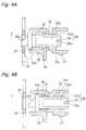
- the spool-locking mechanism 8, as shown in Fig. 3 and 4 is provided with: a locking piece 21 mounted on the reel unit 1 allowing it to shift between an advanced position (Fig. 4A) and a retracted position (Fig. 4B); a lock shifting mechanism 22 that shifts the locking piece 21 between the advanced position and the retracted position; and locking recesses 23, provided on the outside . surface of a flange 3b, and into which the tip of the locking piece 21 is engageable when advanced into the advanced position.
- the locking piece 21 has a shifting member 25 fitted, in an accommodating member 24 fixed to the side plate 11, to allow it to shift along an axis parallel to the spool shaft 2.
- the shifting member 25, which is a rod-shaped, has, from the leading-end side, a locking protrusion 25a, a brim 25b, a shaft 25c, and chamfered portions 25d.
- the upstream side in the line reel-out direction (indicated by the arrow in Fig. 4) of the locking protrusion 25a, which is a protrusion for engagement with the locking recesses 23, is formed at an acute angle, and the downstream side at an a obtuse angle.
- the brim 25b is for interlocking with a coil spring 26 that is component of the lock shifting mechanism 22.
- the coil spring 26 is disposed inside the accommodating member 24 around the shaft 25c of the shifting member 25. The coil spring 26 urges the shifting member 25 toward the locking recesses 23.
- the shaft 25c is supported permitting it to shift axially in the accommodating member 24.
- the shaft 25c is also non-rotatably interlocked with the accommodating member 24 by the chamfered portions 25d. That is, a rounded notch 24a into which the chamfered portions 25d can interlock is formed in one end of the accommodating member 24.
- the shifting member 25 is mounted to the reel unit 1 non-rotatably yet allowed to shift axially.
- a radially extending through-hole 25e is formed in the shifting member 25 at the rear end of the chamfered portions 25d.
- a cam pin 30 that is a component of the lock shifting mechanism 22 is fitted in the through-hole 25e. The cam pin 30 also acts as a locator for the shifting member 25 on the advanced-position end.
- the locking recesses 23 are constituted by cut-outs, circumferentially spaced along the rotational direction, in a lock plate 28.
- the lock plate 28 is a ring-shaped plate that is fastened to the outer surface of the right flange 3b on the spool 3 in Fig. 1.
- an annular recessed escape portion 3c is formed opposing the locking recesses 23. Forming the escape portion 3c in this fashion lets the locking protrusion 25a of the shifting member 25 penetrate the locking recess 23.
- the lock shifting mechanism 22 includes a locking lever 27 mounted to the side plate 11 for pivoting around the shifting member 25 shaft, the coil spring 26 mentioned above, and a locking cam mechanism 29, which in response to pivoting by the locking lever 27 shifts the shifting member 25 from the advanced position into the retracted position against the spring force of the coil spring 26.
- the locking lever 27 is urged by a toggle spring 37 into an advancing posture, indicated by phantom lines and corresponding to the advanced position, and a retracting posture, indicated by solid lines and corresponding to the retracted position.
- the locking cam mechanism 29 includes a slanted cam surface 27a formed helically on the base-end inner wall surface of the locking lever 27, and the cam pin 30 mounted to the rear end of the shifting member 25 so as to engage the slanted cam surface 27a.
- the handle 4 is fastened by a fastening bolt 60 to the protruding end of the cylindrical handle shaft 5, which runs parallel to the spool shaft 2.
- a brim 60a is formed on the fastening bolt 60. Twelve circumferentially spaced arcuate recesses 60b are formed on the brim 60a, and is locked in place by a screw 61, the head of which engages a recess 60b.
- the handle shaft 5 is rotatively mounted in a cylindrical member 15a inserted into the bearing block 15 frontward below the boss portion 11a.
- a main gear 16 is mounted non-rotatably to the tip of the handle shaft 5.
- the rotation transmission mechanism 6 includes: the main gear 16, which is supported rotatively by the handle shaft 5 for the handle 4; and the pinion gear 17, which is formed unitarily with the spool shaft 2. Rotation from the handle 4 is transmitted to the spool shaft 2 via the handle shaft 5, the main gear 16, and the pinion gear 17.
- the lever drag mechanism 7 includes: the brake disk 35, which is mounted on the outside face of the Fig. 1 left-side flange 3b on the spool 3; the friction disk 36, which is disposed for contacting the brake disk 35; and the drag shifting mechanism 38, which is for reciprocatingly shifting the spool 3 and the friction disk 36 in the spool axial direction.
- the brake disk 35 is for example a washer-shaped disk member made of stainless steel, and is mounted non-rotatably with respect to the spool 3 on the outside face of the left-side flange 3b on the spool 3 by means of a radially inward, circumferentially spaced plurality of attaching screws 40 disposed on the lateral surface.
- An attaching portion 35a for attaching the screws 40 on the brake disk 35 is annularly depressed below the radial outward portion. This keeps the drag area, in particular the radially outward drag area, from being restricted, which makes the maximum diameter of the brake disk 35 corresponding to the outer diameter of the spool 3 usable.
- the friction disk 36 is disposed opposing the brake disk 35.
- a ring-shaped friction plate 36a made of abrasion-resistant material, for example carbon graphite or fiber-reinforced resin, is fastened to the surface of the friction disk 36 that opposes the brake disk 35, by an appropriate fastening means, such as screws.
- a tubular boss portion 36b that protrudes axially outward; and a pin 2a, which is fitted into the spool shaft 2, penetrating through the spool shaft 2 diametrically, interlocks with the boss portion 36b. Accordingly, the friction disk 36 is mounted on the spool shaft 2 non-rotatably and rotates together with the spool shaft 2.
- a ratchet wheel 50 in the anti-reverse mechanism 9 is fitted, non-rotatably yet free to shift axially, to the Fig. 1 left-end surface of the boss portion 36b on the friction disk 36.
- a cover member 39 covers the friction disk 36.
- the boss portion 36b on the friction disk 36 passes through the cover member 39 and extends toward the bearing 31a.
- a sealing member 39a is interposed between the penetrated part of the cover member 39 and the boss portion 36b.
- the anti-reverse mechanism 9 is a ratchet-type one-way clutch that includes: a ratchet wheel 50 (one example of a rotary member) on the circumferential surface of which saw-teeth 50a are formed; and a pair of ratchet pawls 51 (one example of ratchet members) whose tips interlock with the saw teeth 50a, and which are disposed on the outer peripheral side of the ratchet wheel 50.
- the ratchet wheel 50 is mounted non-rotatably yet free to shift axially outward (to the left in Fig. 1) by a suitable interlocking means, for example by serrations, to the outer peripheral surface of the boss portion 36b on the friction disk 36. Consequently the ratchet wheel 50 is mounted via the friction disk 36 to the spool shaft 2 (one example of a link member), non-rotatably yet free to shift axially.
- the ratchet wheel 50 has a ring-shaped abutting member 54 coaxially fitted to its Fig. 1 left-side face.
- the abutting member 54 abuts on the right-side end face of the bearing 31a inner race, and on its outer peripheral surface is an alignment portion 54a disposed adjacent the inner peripheral surface of the bearing accommodating portion 10a.
- an alignment portion 54a disposed adjacent the inner peripheral surface of the bearing accommodating portion 10a.
- the ratchet wheel 50 is anchored to the side plate 10 by a pair of braces 55.
- the braces 55 are plate-like members made of metal, for example a stainless steel alloy, with the one ends 55a fastened to the side plate 10.
- the braces 55 are formed into central portions 55b, bent from the first end portions 55a out toward the friction disk 36 into a crank-shape spanning the ratchet pawls 51, and are formed into fastening portions 55c, bent in toward the side plate 10a into a crank-shape.
- the fastening portions 55c are also fastened to the side plate 10. Further, the other ends 55d are formed bent into a crank-shape crooking from the fastening portions 55c toward the ratchet wheel.
- the other ends 55d are disposed in a position opposing the ratchet wheel 50 lateral surface on the friction disk 36 side.
- the ratchet wheel 50 is anchored by these other ends 55d.
- the ratchet pawls 51 are anchored, and their axial travel restrained, by the central portions 55b.
- the pair of ratchet pawls 51 is disposed in positions that are point-symmetrical with respect to the spool shaft axis, and is mounted to the inside surface of the side plate 10 free to pivot between a contact posture, in which they are in contact with the saw-teeth 50a, and a separated posture, in which they are separated from the saw teeth 50a.
- the tips of the ratchet pawls 51 are disposed downstream from the pivotal axes in the line take-up direction R of the ratchet wheel 50.
- a pair of pawl bosses 10b, for pivotally mounting the ratchet pawls 51, is formed on the side plate 10 in symmetrical positions astride the bearing accommodating member 10a.
- two attachment bosses 10c are formed astride the pawl bosses 10b of the pair.
- Pivot pins 53 for mounting the ratchet pawls 51 pivotally to the side plate 10 are fitted into the pawl bosses 10b.
- the pivot pins 53 are anchored by the braces 55, which restrains their axial travel.
- the two attachment bosses 10c are provided for fastening the braces 55 by screwing fast the one ends 55a and the fastening portions 55c to the side plate 10.
- a grasping member (one example of an urging means) 52 which is bent over into a C-shape, is fitted on and fastened to the central portion of the ratchet pawls 51.
- a pair of tips 52a on the grasping member 52 grasps the ratchet wheel 50 by resiliently contacting either lateral face of the ratchet wheel 50.
- the grasping members 52 urge the ratchet pawls 51 into the separated posture under friction with the ratchet wheel 50.
- the urged ratchet pawls 51 come into contact with the braces 55 and are retained in the separated position.
- the friction disk 36 cannot shift in the axially outward direction of the spool shaft (leftward in Fig. 1), i.e., in the direction parting away from the brake disk 35; and meanwhile it is permitted by the anti-reverse mechanism 9 to rotate in the line take-up direction but prohibited from rotating in the line reel-out direction.
- a gap opens between the friction plate 36a on the friction disk 36, and the brake disk 35; and in the braked state as shown above the spool-shaft axis in Fig. 1, the two adhere.
- the drag force is changed by adjusting the degree of adherence.
- the drag shifting mechanism 38 includes: a brake handling lever 45 provided pivotally on the reel unit 1; a pressing mechanism 46, which, in response to pivoting the brake handling lever 45 clockwise in Fig. 2, presses against the spool 3 and the brake disk 35 and shifts them leftward in Fig. 1; and a return spring 47, which is disposed between the friction disk 36 and the spool 3, and shifts the spool rightward in Fig. 1 in response to the brake handling lever 45 moving counterclockwise in Fig. 2.
- the return spring 47 is fitted circumferentially about the spool shaft 2, in the compressed state in between the friction disk 36 and the bearing 32a; and the friction disk 36 urges the brake disk 35 (the spool 3) into the separated direction, urging the brake disk 35 (the spool 3) rightward in Fig. 1.
- the brake handling lever 45 is mounted to the reel unit 1 free to pivot between the brake release position, as shown by the solid line in Fig. 2, and the maximum braking position, indicated by phantom lines.
- the brake handling lever 45 includes a lever portion 45a that is pivotally mounted to the boss portion 11a, and a knob portion 45b that is fastened to the tip end of the lever portion 45a.
- the base end of the lever portion 45a interlocks non-rotatably with the pressing mechanism 46.
- the ratchet wheel 50 when a fish is caught on the tackle and the spool 3 spins in the line reel-out direction, the ratchet wheel 50 also rotates in the line reeling-out direction.
- the graspers 52 under friction with the ratchet wheel 50 are yanked in the line reeling-out direction, reverse to the line reeling-in direction R. Consequently, the ratchet pawls 51 are urged into the contact posture by the graspers 52 and pivot into the contact posture.
- the ratchet wheel 50 when the spool 3 is rotated in the line reeling-out direction, the ratchet wheel 50 is prohibited from rotating in the line reeling-out direction. Consequently the friction disk 36 is stopped from rotating in the line reeling-out direction, and the set drag force is applied to the spool 3.
- the handle 4 When winding fishing line onto the spool, the handle 4 is rotated in the line take-up direction. Doing so transmits the handle 4 rotation to the spool 3 via the handle shaft 5, the main gear 16, the pinion gear 17, the spool shaft 2, and the lever drag mechanism 7, rotating the spool 3.
- the locking lever 27 is pivoted from the position indicated by solid lines in Fig. 2 into the position indicated by phantom lines. This causes the shifting member 25 urged by the coil spring 26 to advance into the advanced position, interlocking the locking protrusion 25a with a locking recess 23, and locking the spool 3 against rotation in the line reeling-out direction.
- the fishing rod is pointed toward the tackle and tugged directly back. Doing this breaks the snag, or the snagged fishing hook(s), fishing line or tangle therein, so that the terminal tackle or a portion of the tackle may be recovered.
- the shifting member 25 undergoes force by the brim 25b and the shaft 25c coming into contact with the accommodating member 24.
- the spool 3 is locked by engagement of the shifting member 25 with a locking recess 23 provided on the spool 3, which means that the spool 3 is locked directly and that the spool-locking mechanism 8 is less likely to damaged or deformed, even if acted upon by abnormal force.
- providing the locking recesses 23 on the outside face of the flange 3b disposes the locking recesses 23 in a section that is equal to or greater than the normal winding diameter of the fishing line when the fishing line is being reeled out. For this reason, the force acting on the shifting member 25 is equal to or less than the tension on the fishing line. This makes it even more unlikely that the spool-locking mechanism 8 will be broken or deformed.
- the locking protrusion 25a is obtuse-angled on its downstream side on the line reeling-out direction, and because the shifting member 25 is urged by the coil spring 26, when the spool 3 rotates in the line take-up direction the shifting member 25 is pressed by the locking recesses 23 and shifts into the retracted position.
- the shifting member 25 is pressed by the locking recesses 23 and shifts into the retracted position.
- a rotary member is fitted free to shift axially onto a link member, and meanwhile is anchored against the reel body by anchoring means.
- the rotary member therefore stays in the reel body and does not shift axially.
- the urging members to which the pawls are fitted are not liable to deform when the link member is removed/attached.
Landscapes
- Life Sciences & Earth Sciences (AREA)
- Environmental Sciences (AREA)
- Animal Husbandry (AREA)
- Biodiversity & Conservation Biology (AREA)
- Storing, Repeated Paying-Out, And Re-Storing Of Elongated Articles (AREA)
- Magnetic Bearings And Hydrostatic Bearings (AREA)
- Braking Arrangements (AREA)
- Replacement Of Web Rolls (AREA)
Abstract
Description
- The present invention relates to anti-reverse mechanisms; in particular to dual-bearing reel anti-reverse mechanisms for governing rotation, in the line reel-out direction, of the spool mounted rotatively in the reel body of the dual-bearing reel.
- In general anti-reverse mechanisms for prohibiting, when the drag is on, rotation in the line reel-out direction of a link member co-operational with the spool, are fitted to drag devices in dual-bearing reels. In the case for example of star-drag model drag devices provided surrounding the handle shaft, the anti-reverse mechanism is fitted to the handle shaft. In the case also of lever-drag model drag devices provided encompassing the spool shaft, the anti-reverse mechanism is provided on the spool shaft or the drag disk(s).
- Ratchet-type anti-reverse mechanisms are generally employed in the type of anti-reverse mechanisms used in lever-drag reel braking devices. Ratchet-type anti-reverse mechanisms have: a rotary member fitted non-rotatably to the link member, and on the outer periphery of which circumferentially spaced teeth are formed; pawls fitted on the reel body pivotally between a contact posture in which they contact, and a separated posture in which they are parted away from, the teeth on the rotary member; and urging members that urge the pawls toward the contact posture. The pawls are disposed with the leading ends downstream from the pivot centers in the line take-up direction.
- With thus configured ratchet-type anti-reverse mechanisms, when the rotary member rotates in the line take-up direction cooperatively with spool rotation in the line take-up direction, the pawls are pressed toward the separated posture by the teeth. If the teeth pass beyond the pawls, however, they are urged toward the contact posture by the urging member, and come into contact with the rotary member. For this reason, when the spool rotates in the line take-up direction, the pawls in the swung state contact the rotary member and produce an intermittent clicking sound. This sort of clicking sound being produced becomes unpleasant when jigging or like angling in which the wind-in operation is repeated frequently and the noise is continual. Moreover, because the pawls contact the rotary member, the rotational resistance during wind-in increases, and the wind-in efficiency degrades.
- Therein, to get rid of the clicking sound during line take-up, instead of urging by means of a spring, mechanisms furnished with urging members that by friction urge the pawls are known. The urging members are constituted by a thin plate element bent into a C-shape, and are fixedly fitted onto the pawls. The tips of the pair of urging members grasp the rotary member by elastic contact on either lateral surface of the rotary member. In anti-reverse mechanisms furnished with this sort of friction-based urging member, when the rotary member rotates in the line take-up direction, the pawls are urged under friction toward the separated posture, and when it rotates in the line reel-out direction, urged under friction toward the separated posture. The clicking sound is therefore not produced during line take-up.
- With the foregoing anti-reverse mechanisms, in disassembling for maintenance, parts replacement, or the like, when the link member for the handle shaft, spool shaft, etc. is taken out, the rotary member can happen to move together with the link member. It the rotary member shifts together with the link member, there is a chance the urging members grasping the rotary member will deform. To prevent this the rotary member should be disposed to allow it to travel axially relative to the link member.
- Though the rotary member is disposed this way to allow it to travel, due to the influence of lubricant such as grease and the effect of friction, there is a chance that the rotary member will be shifted, even if slightly, by the movement of the link member. Even shifting slightly like this still risks that the urging members, constituted by a comparatively thin plate element, will deform.
- Frictional force will not be produced between the urging members and the rotary member if the urging members deform, which means that the pawls cannot be urged normally. Consequently, the anti-reverse mechanism will not function normally.
- An object of the present invention is in an anti-reverse mechanism furnished with urging members that under friction with the rotary member urge the pawls, to keep the urging members from deforming when the link member is removed/attached.
- A dual-bearing reel anti-reverse mechanism according to a first aspect of the invention the is a mechanism for governing rotation of the dual-bearing reel spool, rotatively fitted in the reel body, in the line reeling -out direction, and is furnished with: a rotary member, a pawl member, anchoring means, and urging means. A circumferentially spaced plurality of teeth is formed on the outer periphery of rotary member, which is fitted non-rotatably yet free to shift axially onto a link member for linking with the spool. The pawl member is mounted on the reel body to allow its leading end to pivot between a contact posture in which the leading end contacts, and a separated posture in which it is parted away from, the teeth. The pawl member is mounted such that when the leading end is disposed in the contact posture, it prohibits rotation of the rotary member in the line reel-out direction. The anchoring means is an expedient provided on the reel body to anchor the rotary member against the reel body. The urging means is fitted to the pawl member and urges the pawl member toward the separated posture when the rotary member is rotated in the line wind-in direction. When the rotary member is rotated in the line reel-out direction, the urging means urges the rotary member toward the contact posture.
- When the spool rotates in the line take-up direction by likewise rotation of the handle, the rotary member also rotates in the line take-up direction. In this anti-reverse mechanism thus directed rotation causes the urging means to urge the pawl toward the separated posture. The pawl thereby no longer strikes on the rotary member, keeping sound from being produced. Further, when the spool rotates in the line reel-out direction and the rotary member is about to rotate likewise, the urging means urges the pawl member toward the contact position. This prohibits rotation of the rotary member in the line reel-out direction, so that the drag is operational. To carry out maintenance or other work on the anti-reverse mechanism will be taken apart. In the anti-reverse mechanism configured as above, however, the rotary member is fitted free to shift axially onto the link member but at the same time is anchored to the reel body by the anchoring means. Therefore during removal/attachment the rotary member stays in the reel body and does not shift axially. Accordingly, the urging member fitted to the pawl member is not liable to deform when the link member is removed/attached.
- A dual-bearing reel anti-reverse mechanism according to a second aspect of the invention is the urging means in the mechanism in the foregoing first aspect, being provided on the pawl member and having a grasping member that resiliently grasps either lateral face of the rotary member. Herein, the grasping member though resiliently grasping either lateral face of the rotary member is unlikely to deform when the linking member is removed/attached. Moreover, since either lateral face of the rotary member is grasped and urged, the reliability of the urging function is improved.
- A dual-bearing reel anti-reverse mechanism according to a third aspect of the invention is the anchoring means in the mechanism in the foregoing first or second aspects, anchoring the pawl member against the reel body. Herein since the pawl member is in addition to the rotary member anchored, the pivotal support structure for the pawl on the reel body is simplified.
- A dual-bearing reel anti-reverse mechanism according to a fourth aspect is, in the mechanism set forth in any of the first through third aspects, further furnished with alignment means enabling the rotary member to align with respect to the reel body so as to match the rotational axis of the rotary member and the rotational axis of the link member. Herein the rotary member is aligned when fitted to the reel body, which makes it easier to put in the rotary member during assembly.
- A dual-bearing reel anti-reverse mechanism according to a fifth aspect is the anchoring means in the mechanism in any of the foregoing first through fourth aspects, being a plate-shaped member fixed to the reel body, and disposed with one end in a position opposing the lateral face of said rotary member that is reverse to the reel body. Herein, the anchoring means is constituted by a plate-shaped component, and therefore the constitution of the anchoring means is simple.
- A dual-bearing reel anti-reverse mechanism according to a sixth aspect is the link member in the mechanism in any of the foregoing first through fifth aspects, being the spool shaft relatively supporting the spool. Herein―in an anti-reverse mechanism employed in a lever-drag type drag mechanism―deformation of the urging member is prevented.
- A dual-bearing reel anti-reverse mechanism according to a seventh aspect of the invention is the link member in the mechanism in any of the foregoing first through sixth aspects, being the shaft for the spool-cranking handle. Herein―in an anti-reverse mechanism employed in star-drag type drag mechanism―deformation of the urging member is prevented.
- From the following detailed description in conjunction with the accompanying drawings, the foregoing and other objects, features, aspects and advantages of the present invention will become readily apparent to those skilled in the art.
-
- Fig. 1 is a sectional view of a lever-drag reel in one embodiment of the present invention;
- Fig. 2 is a lateral view of the Fig. 1 lever-drag reel;
- Fig. 3 is an exploded oblique view of a spool-locking mechanism from the Fig. 1 reel;
- Fig. 4A and 4B are enlarged fragmentary sectional views of the spool-locking mechanism;
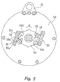
- Fig. 5 is an enlarged elevational view of an anti-reverse mechanism from the Fig. 1 reel; and
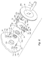
- Fig. 6 is an exploded oblique view of the anti-reverse mechanism.
-
- In Fig. 1, a dual-bearing reel in which an embodiment of the present invention is adapted, is a lever-drag reel furnished with: a cylindrical reel unit 1, a
spool shaft 2 mounted rotatively in the central part of the reel unit 1, a spool 3 rotatively but axially immovably supported on thespool shaft 2, and a handle 4 disposed laterally on the reel unit 1. In the reel unit 1 interior, the lever drag reel is provided with: a rotation transmission mechanism 6 for transmitting to the spool 3 rotation of the handle 4, a lever drag mechanism 7 for braking rotation of the spool 3 in its line reeling-out direction, a spool-locking mechanism 8 for locking the spool 3, and an anti-reverse mechanism 9 for restraining rotation of the lever drag mechanism 7 in the reeling-out direction. - The reel unit 1 has: a left/right pair of plate-shaped
side plates cylindrical reel body 12, made of metal, to either end of which theside plates fastening bolts 13. Harness lugs 14 of a pair, used for supporting the reel with the body, are mounted in between theside plates reel body 12. The approximately central portions of theside plates spool shaft 2. A cylindricalbearing accommodating portion 10a that protrudes inward is formed in the central portion of the inside face of theleft side plate 10. Also, a finishing process that takes away bulk is carried out on theinner margin 10d of the spigot joint section of theleft side plate 10, by undercutting the inner margin in a way that avoids thefastening bolts 13. This serves to make the reel unit 1 lightweight. A boss 11a protruding axially outward is formed in the central portion of the right side plate 11 (handle 4 side) for supporting thespool shaft 2; and on the periphery of the boss 11a, a thick-walled, disk-shapedbearing block 15 for mounting thehandle shaft 5 of the handle 4 is screwed fast. The under portion of thereel body 12 is provided with arod attachment part 19 for mounting the reel onto a fishing rod. - By a pair of left and
right bearings 31a, 31b disposed at either end, thespool shaft 2 is rotatively supported in theside plates bearings bearing 31a on the left side is accommodated by the bearingaccommodating portion 10a formed on theleft side plate 10. The bearing 31b on the right side is mounted in the boss 11a formed on theright side plate 11. The components of a drag shifting mechanism 38 (described later) for the lever drag mechanism 7 adjoins the right side of the bearing 31b outer race on the right end of thespool shaft 2. Additionally, a pinion gear 17 (described later) for the rotation transmission mechanism 6 adjoins the left side of the bearing 31b inner race. The anti-reverse mechanism 9 adjoins the right side of thebearing 31a inner race on the left end of thespool shaft 2. Further, the inside face of theside plate 10 abuts the left end of the outer race. The spool 3 abuts on the left side of the outer race of the right-side bearing 32b that supports the spool 3. Further, four disk springs 34 abut on the right side of the inner race via a washer (not shown). The disk springs 34 are provided in order to make the drag force adjustable over a broad range with respect to pivot of the brake operating lever (described below), without the drag force elevating abruptly. A later describedfriction disk 36 in the lever drag mechanism 7 via a return spring 47 abuts on the left side of the inner race of theleft bearing 32a that supports the spool 3. The right side of the outer race abuts on the spool 3. - The spool 3 has a
bobbin trunk 3a, andflanges 3b that are formed integrally with thebobbin trunk 3a on either end. The spool-locking mechanism 8 is provided outward of theflange 3b on the right side (handle-mounting side) in Fig. 1. Further, abrake disk 35 for the lever drag mechanism 7 is mounted outward of theflange 3b on the left side in Fig. 1. The outer periphery of theleft flange 3b is formed into acylindrical portion 3d extending outward in the spool shaft direction, for attaching acover 39 for covering thebrake disk 35. The innerperipheral surface 3e of thecylindrical part 3d is finished by undercutting to take away bulk. This serves to make the spool 3 lightweight and reduces the inertia of the spool 3. - The spool-locking mechanism 8 permits rotation of the spool 3 in the line wind-in direction, and locks it from rotating in the line reeling-out direction, and as shown in Fig. 2, is disposed neighboring the rear of the reel unit 1. The spool-locking mechanism 8, as shown in Fig. 3 and 4, is provided with: a locking
piece 21 mounted on the reel unit 1 allowing it to shift between an advanced position (Fig. 4A) and a retracted position (Fig. 4B); alock shifting mechanism 22 that shifts the lockingpiece 21 between the advanced position and the retracted position; and lockingrecesses 23, provided on the outside . surface of aflange 3b, and into which the tip of the lockingpiece 21 is engageable when advanced into the advanced position. - The locking
piece 21 has a shiftingmember 25 fitted, in anaccommodating member 24 fixed to theside plate 11, to allow it to shift along an axis parallel to thespool shaft 2. The shiftingmember 25, which is a rod-shaped, has, from the leading-end side, a lockingprotrusion 25a, abrim 25b, ashaft 25c, and chamferedportions 25d. The upstream side in the line reel-out direction (indicated by the arrow in Fig. 4) of the lockingprotrusion 25a, which is a protrusion for engagement with the locking recesses 23, is formed at an acute angle, and the downstream side at an a obtuse angle. While the thus formed lockingprotrusion 25a is interlocked with a lockingrecess 23, when the lockingrecess 23 comes into contact with the acute-angled side, the shiftingmember 25, even if somewhat tilted, will securely bite into the lockingrecess 23 and lock the spool 3; and when the lockingrecess 23 comes into contact with the obtuse-angled side, the shiftingmember 25 will be retractable by action of the lockingrecess 23. Thebrim 25b is for interlocking with acoil spring 26 that is component of thelock shifting mechanism 22. Thecoil spring 26 is disposed inside the accommodatingmember 24 around theshaft 25c of the shiftingmember 25. Thecoil spring 26 urges the shiftingmember 25 toward the locking recesses 23. Theshaft 25c is supported permitting it to shift axially in the accommodatingmember 24. Theshaft 25c is also non-rotatably interlocked with the accommodatingmember 24 by the chamferedportions 25d. That is, arounded notch 24a into which the chamferedportions 25d can interlock is formed in one end of the accommodatingmember 24. Thus, the shiftingmember 25 is mounted to the reel unit 1 non-rotatably yet allowed to shift axially. A radially extending through-hole 25e is formed in the shiftingmember 25 at the rear end of the chamferedportions 25d. Acam pin 30 that is a component of thelock shifting mechanism 22 is fitted in the through-hole 25e. Thecam pin 30 also acts as a locator for the shiftingmember 25 on the advanced-position end. By means of the lockingprotrusion 25a conformed as noted above, and the pressing force due to thecoil spring 26, when the shiftingmember 25 shifted into the advanced position engages a lockingrecess 23, rotation in the line reel-in direction is permitted and rotation in the line reel-out direction is locked. - The locking recesses 23 are constituted by cut-outs, circumferentially spaced along the rotational direction, in a
lock plate 28. Thelock plate 28 is a ring-shaped plate that is fastened to the outer surface of theright flange 3b on the spool 3 in Fig. 1. In the outer surface of the spool 3flange portion 3b where the locking recesses 23 are formed, an annular recessed escape portion 3c is formed opposing the locking recesses 23. Forming the escape portion 3c in this fashion lets the lockingprotrusion 25a of the shiftingmember 25 penetrate the lockingrecess 23. - The
lock shifting mechanism 22 includes a lockinglever 27 mounted to theside plate 11 for pivoting around the shiftingmember 25 shaft, thecoil spring 26 mentioned above, and alocking cam mechanism 29, which in response to pivoting by the lockinglever 27 shifts the shiftingmember 25 from the advanced position into the retracted position against the spring force of thecoil spring 26. As shown in Fig. 2, the lockinglever 27 is urged by atoggle spring 37 into an advancing posture, indicated by phantom lines and corresponding to the advanced position, and a retracting posture, indicated by solid lines and corresponding to the retracted position. The lockingcam mechanism 29 includes a slantedcam surface 27a formed helically on the base-end inner wall surface of the lockinglever 27, and thecam pin 30 mounted to the rear end of the shiftingmember 25 so as to engage the slantedcam surface 27a. - As shown in Fig. 1 and 2, below the
spool shaft 2 the handle 4 is fastened by afastening bolt 60 to the protruding end of thecylindrical handle shaft 5, which runs parallel to thespool shaft 2. Abrim 60a is formed on thefastening bolt 60. Twelve circumferentially spacedarcuate recesses 60b are formed on thebrim 60a, and is locked in place by ascrew 61, the head of which engages arecess 60b. Thehandle shaft 5 is rotatively mounted in acylindrical member 15a inserted into the bearingblock 15 frontward below the boss portion 11a. Amain gear 16 is mounted non-rotatably to the tip of thehandle shaft 5. - As shown in Fig. 1, the rotation transmission mechanism 6 includes: the
main gear 16, which is supported rotatively by thehandle shaft 5 for the handle 4; and thepinion gear 17, which is formed unitarily with thespool shaft 2. Rotation from the handle 4 is transmitted to thespool shaft 2 via thehandle shaft 5, themain gear 16, and thepinion gear 17. - As shown in Fig. 1, the lever drag mechanism 7 includes: the
brake disk 35, which is mounted on the outside face of the Fig. 1 left-side flange 3b on the spool 3; thefriction disk 36, which is disposed for contacting thebrake disk 35; and thedrag shifting mechanism 38, which is for reciprocatingly shifting the spool 3 and thefriction disk 36 in the spool axial direction. - The
brake disk 35 is for example a washer-shaped disk member made of stainless steel, and is mounted non-rotatably with respect to the spool 3 on the outside face of the left-side flange 3b on the spool 3 by means of a radially inward, circumferentially spaced plurality of attachingscrews 40 disposed on the lateral surface. An attachingportion 35a for attaching thescrews 40 on thebrake disk 35 is annularly depressed below the radial outward portion. This keeps the drag area, in particular the radially outward drag area, from being restricted, which makes the maximum diameter of thebrake disk 35 corresponding to the outer diameter of the spool 3 usable. - The
friction disk 36 is disposed opposing thebrake disk 35. A ring-shapedfriction plate 36a made of abrasion-resistant material, for example carbon graphite or fiber-reinforced resin, is fastened to the surface of thefriction disk 36 that opposes thebrake disk 35, by an appropriate fastening means, such as screws. In the central portion of thefriction disk 36 is atubular boss portion 36b that protrudes axially outward; and apin 2a, which is fitted into thespool shaft 2, penetrating through thespool shaft 2 diametrically, interlocks with theboss portion 36b. Accordingly, thefriction disk 36 is mounted on thespool shaft 2 non-rotatably and rotates together with thespool shaft 2. Further, aratchet wheel 50 in the anti-reverse mechanism 9 is fitted, non-rotatably yet free to shift axially, to the Fig. 1 left-end surface of theboss portion 36b on thefriction disk 36. Additionally, acover member 39 covers thefriction disk 36. Theboss portion 36b on thefriction disk 36 passes through thecover member 39 and extends toward thebearing 31a. A sealingmember 39a is interposed between the penetrated part of thecover member 39 and theboss portion 36b. - As shown in Fig. 5 and 6, the anti-reverse mechanism 9 is a ratchet-type one-way clutch that includes: a ratchet wheel 50 (one example of a rotary member) on the circumferential surface of which saw-
teeth 50a are formed; and a pair of ratchet pawls 51 (one example of ratchet members) whose tips interlock with thesaw teeth 50a, and which are disposed on the outer peripheral side of theratchet wheel 50. - The
ratchet wheel 50 is mounted non-rotatably yet free to shift axially outward (to the left in Fig. 1) by a suitable interlocking means, for example by serrations, to the outer peripheral surface of theboss portion 36b on thefriction disk 36. Consequently theratchet wheel 50 is mounted via thefriction disk 36 to the spool shaft 2 (one example of a link member), non-rotatably yet free to shift axially. Theratchet wheel 50 has a ring-shaped abuttingmember 54 coaxially fitted to its Fig. 1 left-side face. The abuttingmember 54 abuts on the right-side end face of thebearing 31a inner race, and on its outer peripheral surface is analignment portion 54a disposed adjacent the inner peripheral surface of the bearingaccommodating portion 10a. Thus providing the abuttingmember 54 makes theratchet wheel 50 mountable centered with respect to theside plate 10, facilitating assembly of theratchet wheel 50. Now, the outer race of thebearing 31a adjoins theside plate 10, as noted earlier. - The
ratchet wheel 50 is anchored to theside plate 10 by a pair ofbraces 55. Thebraces 55 are plate-like members made of metal, for example a stainless steel alloy, with the one ends 55a fastened to theside plate 10. Thebraces 55 are formed intocentral portions 55b, bent from thefirst end portions 55a out toward thefriction disk 36 into a crank-shape spanning theratchet pawls 51, and are formed intofastening portions 55c, bent in toward theside plate 10a into a crank-shape. Thefastening portions 55c are also fastened to theside plate 10. Further, the other ends 55d are formed bent into a crank-shape crooking from thefastening portions 55c toward the ratchet wheel. The other ends 55d are disposed in a position opposing theratchet wheel 50 lateral surface on thefriction disk 36 side. Theratchet wheel 50 is anchored by theseother ends 55d. Also, theratchet pawls 51 are anchored, and their axial travel restrained, by thecentral portions 55b. - The pair of
ratchet pawls 51 is disposed in positions that are point-symmetrical with respect to the spool shaft axis, and is mounted to the inside surface of theside plate 10 free to pivot between a contact posture, in which they are in contact with the saw-teeth 50a, and a separated posture, in which they are separated from thesaw teeth 50a. The tips of theratchet pawls 51 are disposed downstream from the pivotal axes in the line take-up direction R of theratchet wheel 50. A pair ofpawl bosses 10b, for pivotally mounting theratchet pawls 51, is formed on theside plate 10 in symmetrical positions astride thebearing accommodating member 10a. Further, twoattachment bosses 10c are formed astride thepawl bosses 10b of the pair. Pivot pins 53 for mounting theratchet pawls 51 pivotally to theside plate 10 are fitted into thepawl bosses 10b. Also, the pivot pins 53 are anchored by thebraces 55, which restrains their axial travel. The twoattachment bosses 10c are provided for fastening thebraces 55 by screwing fast the one ends 55a and thefastening portions 55c to theside plate 10. - A grasping member (one example of an urging means) 52, which is bent over into a C-shape, is fitted on and fastened to the central portion of the
ratchet pawls 51. A pair oftips 52a on the graspingmember 52 grasps theratchet wheel 50 by resiliently contacting either lateral face of theratchet wheel 50. When theratchet wheel 50 rotates in the line take-up direction R, the graspingmembers 52 urge theratchet pawls 51 into the separated posture under friction with theratchet wheel 50. The urgedratchet pawls 51 come into contact with thebraces 55 and are retained in the separated position. Again, rotating theratchet wheel 50 reverse to the line reel-out direction urges theratchet pawls 51 into the contact posture under friction with theratchet wheel 50. Accordingly, when line is wound in theratchet pawls 51 no longer contact thesaw teeth 50a on theratchet wheel 50, which suppresses noise. This furthermore curbs increase in rotational resistance, and curbs degradation in the reeling-in efficiency of the spool 3 as well. - As a result, the
friction disk 36 cannot shift in the axially outward direction of the spool shaft (leftward in Fig. 1), i.e., in the direction parting away from thebrake disk 35; and meanwhile it is permitted by the anti-reverse mechanism 9 to rotate in the line take-up direction but prohibited from rotating in the line reel-out direction. - Herein, in the brake-released state as shown beneath the spool-shaft axis in Fig. 1, a gap opens between the
friction plate 36a on thefriction disk 36, and thebrake disk 35; and in the braked state as shown above the spool-shaft axis in Fig. 1, the two adhere. The drag force is changed by adjusting the degree of adherence. - As shown in Fig. 1, the
drag shifting mechanism 38 includes: abrake handling lever 45 provided pivotally on the reel unit 1; apressing mechanism 46, which, in response to pivoting thebrake handling lever 45 clockwise in Fig. 2, presses against the spool 3 and thebrake disk 35 and shifts them leftward in Fig. 1; and a return spring 47, which is disposed between thefriction disk 36 and the spool 3, and shifts the spool rightward in Fig. 1 in response to thebrake handling lever 45 moving counterclockwise in Fig. 2. - The return spring 47 is fitted circumferentially about the
spool shaft 2, in the compressed state in between thefriction disk 36 and thebearing 32a; and thefriction disk 36 urges the brake disk 35 (the spool 3) into the separated direction, urging the brake disk 35 (the spool 3) rightward in Fig. 1. - The
brake handling lever 45 is mounted to the reel unit 1 free to pivot between the brake release position, as shown by the solid line in Fig. 2, and the maximum braking position, indicated by phantom lines. Thebrake handling lever 45 includes alever portion 45a that is pivotally mounted to the boss portion 11a, and aknob portion 45b that is fastened to the tip end of thelever portion 45a. The base end of thelever portion 45a interlocks non-rotatably with thepressing mechanism 46. - The following explains the braking function of the lever drag mechanism 7.
- In the lever drag mechanism 7, when the
brake handling lever 45 is pivoted from the braking position, indicated by phantom lines in Fig. 2, into the brake release position, indicated by solid lines, the state shown above the spool axis in Fig. 1 is switched into the state shown beneath the spool axis. Initially the spool 3 is pressed by the urging force of the return spring 47 and shifted rightward in Fig. 1. A gap thereby opens between thebrake disk 35 and thefriction disk 36. The spool 3 is further pressed via thebearing 32a and shifted rightward. This releases the braking on the spool 3. Meanwhile when the spool 3 shifts, thepressing mechanism 46 is pressed via thebearing 32b, the disk springs 34, thepinion gear 17, and the bearing 31b, and retreats rightward in Fig. 1. Then, when thebrake handling lever 45 is pivoted into the brake release position, there is a shift into the state below the spool-shaft axis in Fig. 1. - On the other hand, when the
brake handling lever 45 is pivoted from the brake release position indicated by solid lines in Fig. 2, into the braking position indicated by phantom lines, the state shown on the lower side of the spool axis in Fig. 1 is switched into the state shown on the upper side. Initially, by pivoting thebrake handling lever 45 thepressing mechanism 46 is shifted leftward in the spool axial direction. This presses on and shifts the outer race of the bearing 31b, and the spool 3 is pressed via thepinion gear 17, the disk springs 34, and thebearing 32b and shifted leftward in the spool axial direction (leftward in Fig. 1). Consequently thebrake disk 35 also shifts leftward axially. As a result, thebrake disk 35 nears thefriction disk 36. Then, when thebrake disk 35 comes into contact with thefriction disk 36, which is axially immovable and non-rotatable in the line reel-out direction, drag force acts on the spool 3. When thebrake handling lever 45 is then pivoted to the maximum pivotal position, pressing force is maximized and thefriction disk 36 pressing on thebrake disk 35 yields large drag force. - In this state, when the spool 3 rotates in the line wind-in direction through rotation of the handle 4, via the
friction disk 36 theratchet wheel 50 is also rotated in the line wind-in direction R (Fig. 5). This tugs thegraspers 52, under friction with theratchet wheel 50, in the line wind-in direction R. Consequently theratchet pawls 51 are urged toward the separated posture by thegraspers 52, and pivot into the separated posture to abut against thebraces 55. Therefore, when the spool 3 rotates in the line wind-in direction, there is no clicking sound produced due to collision between theratchet wheel 50 and theratchet pawls 51. - Meanwhile, when a fish is caught on the tackle and the spool 3 spins in the line reel-out direction, the
ratchet wheel 50 also rotates in the line reeling-out direction. When this happens, thegraspers 52 under friction with theratchet wheel 50 are yanked in the line reeling-out direction, reverse to the line reeling-in direction R. Consequently, theratchet pawls 51 are urged into the contact posture by thegraspers 52 and pivot into the contact posture. For this reason, when the spool 3 is rotated in the line reeling-out direction, theratchet wheel 50 is prohibited from rotating in the line reeling-out direction. Consequently thefriction disk 36 is stopped from rotating in the line reeling-out direction, and the set drag force is applied to the spool 3. - The following explains how the lever drag reel is operated.
- When winding fishing line onto the spool, the handle 4 is rotated in the line take-up direction. Doing so transmits the handle 4 rotation to the spool 3 via the
handle shaft 5, themain gear 16, thepinion gear 17, thespool shaft 2, and the lever drag mechanism 7, rotating the spool 3. - Meanwhile, in the event that the spool 3 locks if the tackle is snagged, the locking
lever 27 is pivoted from the position indicated by solid lines in Fig. 2 into the position indicated by phantom lines. This causes the shiftingmember 25 urged by thecoil spring 26 to advance into the advanced position, interlocking the lockingprotrusion 25a with a lockingrecess 23, and locking the spool 3 against rotation in the line reeling-out direction. In this state, after the line is reeled to take up line slack, the fishing rod is pointed toward the tackle and tugged directly back. Doing this breaks the snag, or the snagged fishing hook(s), fishing line or tangle therein, so that the terminal tackle or a portion of the tackle may be recovered. - Herein the shifting
member 25 undergoes force by thebrim 25b and theshaft 25c coming into contact with the accommodatingmember 24. In this locking, the spool 3 is locked by engagement of the shiftingmember 25 with a lockingrecess 23 provided on the spool 3, which means that the spool 3 is locked directly and that the spool-locking mechanism 8 is less likely to damaged or deformed, even if acted upon by abnormal force. Furthermore, providing the locking recesses 23 on the outside face of theflange 3b disposes the locking recesses 23 in a section that is equal to or greater than the normal winding diameter of the fishing line when the fishing line is being reeled out. For this reason, the force acting on the shiftingmember 25 is equal to or less than the tension on the fishing line. This makes it even more unlikely that the spool-locking mechanism 8 will be broken or deformed. - Because, as described above, the locking
protrusion 25a is obtuse-angled on its downstream side on the line reeling-out direction, and because the shiftingmember 25 is urged by thecoil spring 26, when the spool 3 rotates in the line take-up direction the shiftingmember 25 is pressed by the locking recesses 23 and shifts into the retracted position. Thus, even if the spool 3 is mistakenly rotated in the line take-up direction while the spool is locked, abnormal force does not act on the rotation transmission mechanism 6. - On the other hand, when the
spool shaft 2 is removed together with the spool 3 for reel maintenance or otherwise, due to the viscosity of the grease or to friction it can happen that theratchet wheel 50 will shift together with thespool shaft 2. However, here theratchet wheel 50 is anchored by thebraces 55. This makes theratchet wheel 50 stay on theside plate 10 even if it comes off theboss 36b when thespool shaft 2 is removed together with the spool 3. Thus, when thespool shaft 2 is removed/attached, thegraspers 52 fitted on theratchet pawls 51 will not be deformed or otherwise damaged. -
- (a) In the foregoing embodiment, an anti-reverse mechanism employed in a lever-drag type drag mechanism in which the link member is the spool shaft was explained as an example, but the present invention is applicable to anti-reverse mechanisms employed in star-drag type drag mechanisms in which the link member is the handle shaft.
- (b) In the foregoing embodiment, the urging means were constituted by
graspers that grasp either lateral face of the
ratchet wheel 50, but the urging means may be for contacting only that lateral face on the spool side. - (c) In the foregoing embodiment, the
ratchet wheel 50 is non-rotatably, axially immovably fitted via thefriction disk 36 to thespool shaft 2, but may be fitted directly to thespool shaft 2. -
- According to the present invention, a rotary member is fitted free to shift axially onto a link member, and meanwhile is anchored against the reel body by anchoring means. When the link member is removed/attached, the rotary member therefore stays in the reel body and does not shift axially. Thus, the urging members to which the pawls are fitted are not liable to deform when the link member is removed/attached.
- While only selected embodiments have been chosen to illustrate the present invention, to those skilled in the art it will be apparent from this disclosure that various changes and modifications can be made herein without departing from the scope of the invention as defined in the appended claims. Furthermore, the foregoing description of the embodiments according to the present invention is provided for illustration only, and not for the purpose of limiting the invention as defined by the appended claims.
Claims (7)
- A dual-bearing reel anti-reverse mechanism for governing rotation of the dual-bearing reel spool, rotatively fitted in the reel body, in the line reeling-out direction, the anti-reverse mechanism (9) comprising:a rotary member (50) having a plurality of teeth (50a) formed circumferentially spaced on its outer periphery, fitted non-rotatably yet free to shift axially onto a link member (2, 5) for rotationally co-operative linking with the spool (3);a pawl member (51) mounted on the reel body (12) to allow its leading end to pivot between a contact posture in which the leading end of said pawl member (51) contacts said teeth (50a) and a separated posture in which the leading end is parted away from said teeth (50a), and being mounted such that when disposed in the contact posture said pawl member (51) prohibits rotation of said rotary member (50) in the line reel-out direction;anchoring means (55) provided on the reel body (12), for anchoring said rotary member (50) against the reel body (12); andurging means (52) fitted to said pawl member (51), for urging under friction with said rotary member (50) said pawl member (50) toward the separated posture when said rotary member (50) is line wind-in directionally rotated and urging said pawl member (51) toward the contact posture when said rotary member (50) is line reel-out directionally rotated.
- The dual-bearing reel anti-reverse mechanism as claimed in Claim 1, wherein said urging means (52) is provided on said pawl member (51) and has a grasping member (52) for resiliently grasping either lateral face of said rotary member (50).
- The dual-bearing reel anti-reverse mechanism as claimed in Claim 1 or Claim 2, wherein said anchoring means (55) is for anchoring said pawl member (51) to the reel body (12).
- The dual-bearing reel anti-reverse mechanism as claimed in any preceding claim, further comprising alignment means for enabling said rotary member (50) to align with respect to the reel body (12) such that the rotational axes of said rotary member (50) and of said link member (2, 5) coincide.
- The dual-bearing reel anti-reverse mechanism as claimed in any preceding claim, wherein said anchoring means (55) is a plate-shaped member (55) fixed to the reel body (12), and is disposed with one end in a position opposing the lateral face of said rotary member (50) reverse to the reel body (12).
- The dual-bearing reel anti-reverse mechanism as claimed in any preceding claim, wherein said link member (2, 5) is a spool shaft (2) for rotatively supporting the spool (3).
- The dual-bearing reel anti-reverse mechanism as claimed in any preceding claim, wherein said link member (2, 5) is a shaft (5) for a spool-cranking handle (4).
Applications Claiming Priority (2)
| Application Number | Priority Date | Filing Date | Title |
|---|---|---|---|
| JP2000261523 | 2000-08-30 | ||
| JP2000261523A JP4381580B2 (en) | 2000-08-30 | 2000-08-30 | Double bearing reel reverse rotation prevention mechanism |
Publications (2)
| Publication Number | Publication Date |
|---|---|
| EP1183946A1 true EP1183946A1 (en) | 2002-03-06 |
| EP1183946B1 EP1183946B1 (en) | 2004-10-13 |
Family
ID=18749351
Family Applications (1)
| Application Number | Title | Priority Date | Filing Date |
|---|---|---|---|
| EP01307096A Expired - Lifetime EP1183946B1 (en) | 2000-08-30 | 2001-08-21 | Dual-bearing reel anti-reverse mechanism |
Country Status (9)
| Country | Link |
|---|---|
| US (1) | US6517021B2 (en) |
| EP (1) | EP1183946B1 (en) |
| JP (1) | JP4381580B2 (en) |
| KR (1) | KR100722538B1 (en) |
| CN (1) | CN1225165C (en) |
| AT (1) | ATE279103T1 (en) |
| AU (1) | AU779135B2 (en) |
| DE (1) | DE60106355T2 (en) |
| TW (1) | TW504368B (en) |
Families Citing this family (14)
| Publication number | Priority date | Publication date | Assignee | Title |
|---|---|---|---|---|
| JP4381733B2 (en) * | 2003-06-26 | 2009-12-09 | 株式会社シマノ | Double bearing reel |
| US6634586B1 (en) * | 2002-07-02 | 2003-10-21 | Liang-Jen Chang | Anti-reversional mechanism for trolling reel |
| US7198219B1 (en) * | 2005-05-27 | 2007-04-03 | Harout Alajajyan | Fishing reel transmission |
| US7128287B1 (en) * | 2005-11-10 | 2006-10-31 | Okuma Fishing Tackle Co. Ltd. | Fishing reel |
| GB2461876B (en) * | 2008-07-14 | 2011-03-09 | Lead Innovations | Retracting dog lead with manual override |
| KR101126546B1 (en) * | 2009-06-26 | 2012-03-26 | 주식회사 도요엔지니어링 | bait reel for fishing |
| JP5961378B2 (en) * | 2011-12-22 | 2016-08-02 | 株式会社シマノ | Drag adjusting device for double-bearing reel |
| JP6200287B2 (en) * | 2013-11-14 | 2017-09-20 | シマノコンポネンツ マレーシア エスディーエヌ.ビーエッチディー. | Double bearing reel |
| JP6467218B2 (en) * | 2014-12-19 | 2019-02-06 | 株式会社シマノ | Double bearing reel |
| JP6518514B2 (en) * | 2015-05-28 | 2019-05-22 | 株式会社シマノ | Double bearing reel |
| JP6886344B2 (en) * | 2017-05-17 | 2021-06-16 | 株式会社シマノ | Double bearing reel |
| JP7086827B2 (en) * | 2018-12-14 | 2022-06-20 | 株式会社シマノ | Fishing reel cap |
| CN113049487B (en) * | 2021-03-22 | 2022-03-18 | 北京航空航天大学 | A test system and method for calculating the friction coefficient of inclined roller friction discs |
| US12484564B2 (en) | 2022-01-27 | 2025-12-02 | TrikaUSA Inc. | Anti-reverse mechanism for fishing reel |
Citations (4)
| Publication number | Priority date | Publication date | Assignee | Title |
|---|---|---|---|---|
| US3989204A (en) * | 1968-01-05 | 1976-11-02 | Carpano & Pons S.A. | Fly fishing reel |
| US4899953A (en) * | 1987-05-23 | 1990-02-13 | Shimano Industrial Company Limited | Double bearing fishing reel |
| US5415359A (en) * | 1991-02-05 | 1995-05-16 | Ikuta; Takeshi | Fishing reel |
| US5601246A (en) * | 1994-02-22 | 1997-02-11 | Daiwa Seiko, Inc. | Adjustable thumb placement member for a fishing reel |
Family Cites Families (3)
| Publication number | Priority date | Publication date | Assignee | Title |
|---|---|---|---|---|
| US5201870A (en) * | 1990-12-14 | 1993-04-13 | Newell Carl W | Reverse stop rachet and pawl for a fishing reel |
| US6056223A (en) * | 1996-08-21 | 2000-05-02 | Kirby; Thomas Glen | Drag mounted spring for spin-cast reels |
| AUPO185596A0 (en) * | 1996-08-23 | 1996-09-19 | Jarvis Walker Pty Ltd | A spinning reel for fishing |
-
2000
- 2000-08-30 JP JP2000261523A patent/JP4381580B2/en not_active Expired - Fee Related
-
2001
- 2001-06-15 TW TW090114624A patent/TW504368B/en not_active IP Right Cessation
- 2001-07-06 KR KR1020010040247A patent/KR100722538B1/en not_active Expired - Fee Related
- 2001-08-21 DE DE60106355T patent/DE60106355T2/en not_active Expired - Lifetime
- 2001-08-21 EP EP01307096A patent/EP1183946B1/en not_active Expired - Lifetime
- 2001-08-21 AT AT01307096T patent/ATE279103T1/en not_active IP Right Cessation
- 2001-08-22 AU AU63593/01A patent/AU779135B2/en not_active Ceased
- 2001-08-23 US US09/934,517 patent/US6517021B2/en not_active Expired - Lifetime
- 2001-08-30 CN CNB011258934A patent/CN1225165C/en not_active Expired - Fee Related
Patent Citations (4)
| Publication number | Priority date | Publication date | Assignee | Title |
|---|---|---|---|---|
| US3989204A (en) * | 1968-01-05 | 1976-11-02 | Carpano & Pons S.A. | Fly fishing reel |
| US4899953A (en) * | 1987-05-23 | 1990-02-13 | Shimano Industrial Company Limited | Double bearing fishing reel |
| US5415359A (en) * | 1991-02-05 | 1995-05-16 | Ikuta; Takeshi | Fishing reel |
| US5601246A (en) * | 1994-02-22 | 1997-02-11 | Daiwa Seiko, Inc. | Adjustable thumb placement member for a fishing reel |
Also Published As
| Publication number | Publication date |
|---|---|
| DE60106355T2 (en) | 2006-02-02 |
| TW504368B (en) | 2002-10-01 |
| US20020023978A1 (en) | 2002-02-28 |
| ATE279103T1 (en) | 2004-10-15 |
| EP1183946B1 (en) | 2004-10-13 |
| CN1341354A (en) | 2002-03-27 |
| CN1225165C (en) | 2005-11-02 |
| JP4381580B2 (en) | 2009-12-09 |
| KR100722538B1 (en) | 2007-05-28 |
| AU779135B2 (en) | 2005-01-06 |
| DE60106355D1 (en) | 2004-11-18 |
| KR20020017946A (en) | 2002-03-07 |
| US6517021B2 (en) | 2003-02-11 |
| JP2002065129A (en) | 2002-03-05 |
| AU6359301A (en) | 2002-03-07 |
Similar Documents
| Publication | Publication Date | Title |
|---|---|---|
| EP1181864B1 (en) | Dual-Bearing reel spool-locking mechanism | |
| EP1183946B1 (en) | Dual-bearing reel anti-reverse mechanism | |
| KR101010970B1 (en) | Clutch operating member of both bearing reels | |
| US10010061B2 (en) | Spinning reel | |
| KR20150056031A (en) | Dual-bearing reel | |
| JP2002218870A (en) | Fishing reel seal structure | |
| TW201532516A (en) | Spinning reel | |
| JP2006025763A (en) | Handle-assembling body of fishing reel | |
| TW201119573A (en) | Rotor brake for spinning reel. | |
| CN103210892B (en) | Spinning-reel and the drag switch device of spinning-reel | |
| JP4324268B2 (en) | Double-bearing reel braking device | |
| CN100529453C (en) | One way clutch for spinning reel | |
| JP4834240B2 (en) | Double-bearing reel drag adjustment mechanism | |
| JP6842756B2 (en) | Fishing reel | |
| JP2004222559A (en) | Fishing reel handle device | |
| JP4266719B2 (en) | Spinning reel rotor braking device | |
| JP4834786B2 (en) | Double-bearing reel drag adjustment mechanism | |
| JP4365981B2 (en) | Handle shaft support structure for dual-bearing reels | |
| JP2018186758A (en) | Double bearing fishing reel | |
| JP2000213567A (en) | Fishing tackle reel clutch | |
| JP3542749B2 (en) | Spinning reel for fishing | |
| JPH1189485A (en) | Spinning reel | |
| JP2003047373A (en) | Spinning reel reel body | |
| JP2002000138A5 (en) | ||
| JP2018161139A (en) | Spinning reel |
Legal Events
| Date | Code | Title | Description |
|---|---|---|---|
| PUAI | Public reference made under article 153(3) epc to a published international application that has entered the european phase |
Free format text: ORIGINAL CODE: 0009012 |
|
| AK | Designated contracting states |
Kind code of ref document: A1 Designated state(s): AT BE CH CY DE DK ES FI FR GB GR IE IT LI LU MC NL PT SE TR |
|
| AX | Request for extension of the european patent |
Free format text: AL;LT;LV;MK;RO;SI |
|
| 17P | Request for examination filed |
Effective date: 20020227 |
|
| 17Q | First examination report despatched |
Effective date: 20031020 |
|
| GRAP | Despatch of communication of intention to grant a patent |
Free format text: ORIGINAL CODE: EPIDOSNIGR1 |
|
| AKX | Designation fees paid |
Designated state(s): AT BE CH CY DE DK ES FI FR GB GR IE IT LI LU MC NL PT SE TR |
|
| GRAS | Grant fee paid |
Free format text: ORIGINAL CODE: EPIDOSNIGR3 |
|
| GRAA | (expected) grant |
Free format text: ORIGINAL CODE: 0009210 |
|
| AK | Designated contracting states |
Kind code of ref document: B1 Designated state(s): AT BE CH CY DE DK ES FI FR GB GR IE IT LI LU MC NL PT SE TR |
|
| PG25 | Lapsed in a contracting state [announced via postgrant information from national office to epo] |
Ref country code: AT Free format text: LAPSE BECAUSE OF FAILURE TO SUBMIT A TRANSLATION OF THE DESCRIPTION OR TO PAY THE FEE WITHIN THE PRESCRIBED TIME-LIMIT Effective date: 20041013 Ref country code: TR Free format text: LAPSE BECAUSE OF FAILURE TO SUBMIT A TRANSLATION OF THE DESCRIPTION OR TO PAY THE FEE WITHIN THE PRESCRIBED TIME-LIMIT Effective date: 20041013 Ref country code: LI Free format text: LAPSE BECAUSE OF FAILURE TO SUBMIT A TRANSLATION OF THE DESCRIPTION OR TO PAY THE FEE WITHIN THE PRESCRIBED TIME-LIMIT Effective date: 20041013 Ref country code: FI Free format text: LAPSE BECAUSE OF FAILURE TO SUBMIT A TRANSLATION OF THE DESCRIPTION OR TO PAY THE FEE WITHIN THE PRESCRIBED TIME-LIMIT Effective date: 20041013 Ref country code: CH Free format text: LAPSE BECAUSE OF FAILURE TO SUBMIT A TRANSLATION OF THE DESCRIPTION OR TO PAY THE FEE WITHIN THE PRESCRIBED TIME-LIMIT Effective date: 20041013 |
|
| REG | Reference to a national code |
Ref country code: GB Ref legal event code: FG4D |
|
| REG | Reference to a national code |
Ref country code: CH Ref legal event code: EP |
|
| REG | Reference to a national code |
Ref country code: IE Ref legal event code: FG4D |
|
| REF | Corresponds to: |
Ref document number: 60106355 Country of ref document: DE Date of ref document: 20041118 Kind code of ref document: P |
|
| PG25 | Lapsed in a contracting state [announced via postgrant information from national office to epo] |
Ref country code: SE Free format text: LAPSE BECAUSE OF FAILURE TO SUBMIT A TRANSLATION OF THE DESCRIPTION OR TO PAY THE FEE WITHIN THE PRESCRIBED TIME-LIMIT Effective date: 20050113 Ref country code: GR Free format text: LAPSE BECAUSE OF FAILURE TO SUBMIT A TRANSLATION OF THE DESCRIPTION OR TO PAY THE FEE WITHIN THE PRESCRIBED TIME-LIMIT Effective date: 20050113 Ref country code: DK Free format text: LAPSE BECAUSE OF FAILURE TO SUBMIT A TRANSLATION OF THE DESCRIPTION OR TO PAY THE FEE WITHIN THE PRESCRIBED TIME-LIMIT Effective date: 20050113 |
|
| PG25 | Lapsed in a contracting state [announced via postgrant information from national office to epo] |
Ref country code: ES Free format text: LAPSE BECAUSE OF FAILURE TO SUBMIT A TRANSLATION OF THE DESCRIPTION OR TO PAY THE FEE WITHIN THE PRESCRIBED TIME-LIMIT Effective date: 20050124 |
|
| REG | Reference to a national code |
Ref country code: CH Ref legal event code: PL |
|
| PGFP | Annual fee paid to national office [announced via postgrant information from national office to epo] |
Ref country code: FR Payment date: 20050712 Year of fee payment: 5 |
|
| PGFP | Annual fee paid to national office [announced via postgrant information from national office to epo] |
Ref country code: NL Payment date: 20050808 Year of fee payment: 5 |
|
| PLBE | No opposition filed within time limit |
Free format text: ORIGINAL CODE: 0009261 |
|
| STAA | Information on the status of an ep patent application or granted ep patent |
Free format text: STATUS: NO OPPOSITION FILED WITHIN TIME LIMIT |
|
| PG25 | Lapsed in a contracting state [announced via postgrant information from national office to epo] |
Ref country code: CY Free format text: LAPSE BECAUSE OF FAILURE TO SUBMIT A TRANSLATION OF THE DESCRIPTION OR TO PAY THE FEE WITHIN THE PRESCRIBED TIME-LIMIT Effective date: 20050821 |
|
| PG25 | Lapsed in a contracting state [announced via postgrant information from national office to epo] |
Ref country code: IE Free format text: LAPSE BECAUSE OF NON-PAYMENT OF DUE FEES Effective date: 20050822 |
|
| PGFP | Annual fee paid to national office [announced via postgrant information from national office to epo] |
Ref country code: BE Payment date: 20050826 Year of fee payment: 5 |
|
| PG25 | Lapsed in a contracting state [announced via postgrant information from national office to epo] |
Ref country code: MC Free format text: LAPSE BECAUSE OF NON-PAYMENT OF DUE FEES Effective date: 20050831 |
|
| PGFP | Annual fee paid to national office [announced via postgrant information from national office to epo] |
Ref country code: LU Payment date: 20050916 Year of fee payment: 5 |
|
| ET | Fr: translation filed | ||
| 26N | No opposition filed |
Effective date: 20050714 |
|
| REG | Reference to a national code |
Ref country code: IE Ref legal event code: MM4A |
|
| PG25 | Lapsed in a contracting state [announced via postgrant information from national office to epo] |
Ref country code: BE Free format text: LAPSE BECAUSE OF NON-PAYMENT OF DUE FEES Effective date: 20060831 |
|
| PG25 | Lapsed in a contracting state [announced via postgrant information from national office to epo] |
Ref country code: NL Free format text: LAPSE BECAUSE OF NON-PAYMENT OF DUE FEES Effective date: 20070301 |
|
| NLV4 | Nl: lapsed or anulled due to non-payment of the annual fee |
Effective date: 20070301 |
|
| REG | Reference to a national code |
Ref country code: FR Ref legal event code: ST Effective date: 20070430 |
|
| BERE | Be: lapsed |
Owner name: *SHIMANO INC. Effective date: 20060831 |
|
| PG25 | Lapsed in a contracting state [announced via postgrant information from national office to epo] |
Ref country code: PT Free format text: LAPSE BECAUSE OF NON-PAYMENT OF DUE FEES Effective date: 20050313 |
|
| PG25 | Lapsed in a contracting state [announced via postgrant information from national office to epo] |
Ref country code: FR Free format text: LAPSE BECAUSE OF NON-PAYMENT OF DUE FEES Effective date: 20060831 |
|
| PG25 | Lapsed in a contracting state [announced via postgrant information from national office to epo] |
Ref country code: LU Free format text: LAPSE BECAUSE OF NON-PAYMENT OF DUE FEES Effective date: 20060821 |
|
| PGFP | Annual fee paid to national office [announced via postgrant information from national office to epo] |
Ref country code: DE Payment date: 20090814 Year of fee payment: 9 Ref country code: GB Payment date: 20090818 Year of fee payment: 9 |
|
| PGFP | Annual fee paid to national office [announced via postgrant information from national office to epo] |
Ref country code: IT Payment date: 20090818 Year of fee payment: 9 |
|
| GBPC | Gb: european patent ceased through non-payment of renewal fee |
Effective date: 20100821 |
|
| PG25 | Lapsed in a contracting state [announced via postgrant information from national office to epo] |
Ref country code: IT Free format text: LAPSE BECAUSE OF NON-PAYMENT OF DUE FEES Effective date: 20100821 |
|
| REG | Reference to a national code |
Ref country code: DE Ref legal event code: R119 Ref document number: 60106355 Country of ref document: DE Effective date: 20110301 |
|
| PG25 | Lapsed in a contracting state [announced via postgrant information from national office to epo] |
Ref country code: DE Free format text: LAPSE BECAUSE OF NON-PAYMENT OF DUE FEES Effective date: 20110301 |
|
| PG25 | Lapsed in a contracting state [announced via postgrant information from national office to epo] |
Ref country code: GB Free format text: LAPSE BECAUSE OF NON-PAYMENT OF DUE FEES Effective date: 20100821 |