JP6200287B2 - Double bearing reel - Google Patents
Double bearing reel Download PDFInfo
- Publication number
- JP6200287B2 JP6200287B2 JP2013235777A JP2013235777A JP6200287B2 JP 6200287 B2 JP6200287 B2 JP 6200287B2 JP 2013235777 A JP2013235777 A JP 2013235777A JP 2013235777 A JP2013235777 A JP 2013235777A JP 6200287 B2 JP6200287 B2 JP 6200287B2
- Authority
- JP
- Japan
- Prior art keywords
- claw
- rotation
- drive shaft
- bearing reel
- swing
- Prior art date
- Legal status (The legal status is an assumption and is not a legal conclusion. Google has not performed a legal analysis and makes no representation as to the accuracy of the status listed.)
- Active
Links
Images


Classifications
-
- A—HUMAN NECESSITIES
- A01—AGRICULTURE; FORESTRY; ANIMAL HUSBANDRY; HUNTING; TRAPPING; FISHING
- A01K—ANIMAL HUSBANDRY; CARE OF BIRDS, FISHES, INSECTS; FISHING; REARING OR BREEDING ANIMALS, NOT OTHERWISE PROVIDED FOR; NEW BREEDS OF ANIMALS
- A01K89/00—Reels
- A01K89/015—Reels with a rotary drum, i.e. with a rotating spool
-
- A—HUMAN NECESSITIES
- A01—AGRICULTURE; FORESTRY; ANIMAL HUSBANDRY; HUNTING; TRAPPING; FISHING
- A01K—ANIMAL HUSBANDRY; CARE OF BIRDS, FISHES, INSECTS; FISHING; REARING OR BREEDING ANIMALS, NOT OTHERWISE PROVIDED FOR; NEW BREEDS OF ANIMALS
- A01K89/00—Reels
- A01K89/02—Brake devices for reels
- A01K89/033—Brake devices for reels with a rotary drum, i.e. for reels with a rotating spool
- A01K89/05—Brakes connected to the spool by one-way clutch
Description
本発明は、釣り糸を巻き取る魚釣用リール、特に、両軸受リールに関する。 The present invention relates to a fishing reel for winding a fishing line, and more particularly to a dual-bearing reel.
魚釣用リールには、通常、魚がかかってこれを釣り上げるときには、ハンドルを巻くことにより釣り糸をスプールに巻き採ることができ、反対に糸が自由に繰り出さないように糸繰り出しの方向にはスプールが回転しないようにされる。
しかしながら、魚に釣り糸を引っ張られて釣り糸に過大な張力がかかり、糸が切れてしまう等の不具合の発生を防止するためにドラグ装置が備えられている。
両軸受リールでは、ドラグ装置を作動させるために、スプールの糸繰り出し方向の回転を禁止するためのワンウェイクラッチが装着される。例えば、駆動軸の周りにドラグ装置が設けられるスタードラグ形の両軸受リールの場合、ローラ型のワンウェイクラッチ及び/又は爪式のワンウェイクラッチが、ハンドルが装着される駆動軸に装着される。また、スプール軸の周りにドラグ装置が設けられるレバードラグ型の両軸受リールの場合、スプール軸、駆動軸又はドラグディスクに爪式のワンウェイクラッチが設けられる(例えば、特許文献1参照)。
Normally, when a fish is caught and picked up by a fishing reel, the fishing line can be wound around the spool by winding a handle. Is prevented from rotating.
However, a drag device is provided to prevent the occurrence of problems such as the fishing line being pulled by the fish and excessive tension applied to the fishing line, causing the line to break.
In the dual-bearing reel, a one-way clutch for prohibiting the rotation of the spool in the yarn unwinding direction is mounted to operate the drag device. For example, in the case of a star drag type double-bearing reel in which a drag device is provided around the drive shaft, a roller-type one-way clutch and / or a claw-type one-way clutch is mounted on the drive shaft on which the handle is mounted. In the case of a lever drag type double-bearing reel in which a drag device is provided around the spool shaft, a claw-type one-way clutch is provided on the spool shaft, the drive shaft, or the drag disk (see, for example, Patent Document 1).
従来の爪式のワンウェイクラッチは、駆動軸に連動して回転するラチェットホイールと、ラチェットホイールの糸繰り出し方向の回転を禁止するための爪部材と、を備える。爪部材は、ラチェットホイールから離反する離反位置とラチェット歯に係合する係合位置とに揺動する。従来のワンウェイクラッチは、糸繰り出し時に爪部材を摩擦によって係合位置側に揺動させ、糸巻取時に爪部材を摩擦によって離反位置側に揺動させる揺動制御用の付勢部材を有する。これによって、糸巻取時にワンウェイクラッチが発音しないようになる。揺動制御用の付勢部材は、C字状に折り曲げられた金属製の薄い板状部材で構成され、ラチェット爪にはめ込み固定される。付勢部材の1対の先端は、ラチェットホイールの両側面に弾性的に接触してラチェットホイールを挟持する。 A conventional claw-type one-way clutch includes a ratchet wheel that rotates in conjunction with a drive shaft, and a claw member that prohibits rotation of the ratchet wheel in the yarn unwinding direction. The claw member swings between a separation position that separates from the ratchet wheel and an engagement position that engages with the ratchet teeth. The conventional one-way clutch includes a biasing member for swing control that swings the claw member to the engagement position side by friction when the yarn is fed and swings the claw member to the separation position side by friction when winding the yarn. This prevents the one-way clutch from sounding when winding the yarn. The urging member for swing control is formed of a thin metal plate member bent in a C shape and is fitted and fixed to the ratchet claw. A pair of front ends of the urging members elastically contact both side surfaces of the ratchet wheel to sandwich the ratchet wheel.
従来のラチェットホイールを挟持する揺動制御用の付勢部材が板状の部材で構成されるため、付勢部材が変形しやすい。付勢部材が変形すると、ラチェットホイールとの摩擦力が変化するおそれがある。揺動制御用の付勢部材の摩擦力が変化すると、爪部材が駆動軸の回転に連動して正常に揺動しないおそれがある。 Since the urging member for swing control that sandwiches the conventional ratchet wheel is composed of a plate-like member, the urging member is easily deformed. When the urging member is deformed, the frictional force with the ratchet wheel may change. If the frictional force of the biasing member for swing control changes, the claw member may not swing normally in conjunction with the rotation of the drive shaft.
本発明の課題は、揺動制御用の部材の変形によって生じる摩擦力の変化を抑えることにある。 An object of the present invention is to suppress a change in frictional force caused by deformation of a member for swing control.
本発明に係る両軸受リールは、釣り糸を前方に繰り出すリールである。両軸受リールは、ハンドルと、リール本体と、駆動軸と、ラチェットホイールと、爪部材と、スプールと、爪揺動制御部と、を備える。リール本体は、揺動軸が設けられ、ハンドルが側部に配置されるものである。駆動軸は、リール本体に回転自在に装着され、ハンドルに連動して回転可能である。ラチェットホイールは、周方向に間隔を隔てて配置された複数のラチェット歯を有する。ラチェットホイールは、駆動軸に連動して回転可能である。爪部材は、ラチェット歯に係合する係合位置とラチェット歯から離反する離反位置とに揺動可能に揺動軸に設けられる。スプールは、リール本体に対して回転可能であり、駆動軸の糸巻き取り方向R1の回転によって釣り糸を巻き取り可能である。爪揺動制御部は、揺動軸に回動自在に設けられ、駆動軸の回転に応じて回転する第1回転部材を有し、第1回転部材の回転方向に応じて、爪部材を係合位置及び離反位置に揺動させる。 The dual-bearing reel according to the present invention is a reel that feeds a fishing line forward. Dual-bearing reel includes a handle, a reel body, a drive shaft, a ratchet wheel, a pawl member, a spool, and a pawl swing control unit. The reel body is provided with a swing shaft, and a handle is disposed on a side portion. The drive shaft is rotatably mounted on the reel body and can be rotated in conjunction with the handle. The ratchet wheel has a plurality of ratchet teeth arranged at intervals in the circumferential direction. The ratchet wheel can rotate in conjunction with the drive shaft. The claw member is provided on the swing shaft so as to be swingable between an engagement position for engaging with the ratchet teeth and a separation position for separating from the ratchet teeth. The spool can be rotated with respect to the reel body, and the fishing line can be wound by rotation of the drive shaft in the line winding direction R1. The claw swing control unit is provided rotatably on the swing shaft, has a first rotating member that rotates according to the rotation of the drive shaft, and engages the claw member according to the rotation direction of the first rotating member. Swing to the mating position and separation position.
この両軸受リールでは、駆動軸が糸巻き取り方向に回転すると爪揺動制御部の揺動制御用の第1回転部材も糸巻き取り方向に回転する。第1回転部材が糸巻き取り方向に回転すると、例えば、爪部材を離反位置に揺動させる。一方、駆動軸が糸繰り出し方向に回転すると、第1回転部材も糸繰り出し方向に回転する。第1回転部材が糸繰り出し方向に回転すると、例えば、爪部材を係合位置に揺動させる。これによって、ラチェットホイールの糸繰り出し方向の回転が禁止され、駆動軸も糸繰り出し方向の回転が禁止される。この結果、ドラグ機構を動作させることができる。ここでは、板状の部材でなく、駆動軸の回転に応じて回転する第1回転部材によって、爪部材の揺動を制御するので、揺動制御用の部材の変形が生じにくくなり、変形によって生じる摩擦力の変化を抑えることができる。 In this dual-bearing reel, when the drive shaft rotates in the yarn winding direction, the first rotation member for swing control of the claw swing control unit also rotates in the yarn winding direction. When the first rotating member rotates in the yarn winding direction, for example, the claw member is swung to the separation position. On the other hand, when the drive shaft rotates in the yarn unwinding direction, the first rotating member also rotates in the yarn unwinding direction. When the first rotating member rotates in the yarn feeding direction, for example, the claw member is swung to the engagement position. As a result, rotation of the ratchet wheel in the yarn unwinding direction is prohibited, and rotation of the drive shaft is also prohibited in the yarn unwinding direction. As a result, the drag mechanism can be operated. Here, since the swing of the claw member is controlled not by the plate-like member but by the first rotating member that rotates according to the rotation of the drive shaft, the swing control member is less likely to be deformed. It is possible to suppress changes in the frictional force that occurs.
爪揺動制御部は、駆動軸と連動して回転可能な第2回転部材をさらに有してもよい。第1回転部材は、第2回転部材の回転に連動して回転する。この場合には、第2回転部材を介して駆動軸の回転を第1回転部材に伝達できるので、ラチェットホイールが両軸受リール内のどのような場所に配置されても、第1回転部材を駆動軸に連動して回転させることができる。 The claw swing control unit may further include a second rotating member that can rotate in conjunction with the drive shaft. The first rotating member rotates in conjunction with the rotation of the second rotating member. In this case, since the rotation of the drive shaft can be transmitted to the first rotating member via the second rotating member, the first rotating member can be driven regardless of the position of the ratchet wheel in both bearing reels. It can be rotated in conjunction with the shaft.
第2回転部材は、駆動軸に設けられてもよい。この場合には、ラチェットホイールが駆動軸に設けられる場合に、駆動軸の回転を容易に第1回転部材に伝達できる。また、ラチェットホイールと、駆動軸の回転をスプールに伝達する駆動ギアと、の大きさ又は位置関係に限定されずに第1回転部材を配置できる。 The second rotating member may be provided on the drive shaft. In this case, when the ratchet wheel is provided on the drive shaft, the rotation of the drive shaft can be easily transmitted to the first rotating member. Further, the first rotating member can be arranged without being limited to the size or positional relationship between the ratchet wheel and the driving gear that transmits the rotation of the driving shaft to the spool.
第2回転部材は、駆動軸に設けられ、ハンドルの回転をスプールに伝達するための駆動ギアであってもよい。この場合には、駆動軸の回転を第1回転部材に伝達するための第2回転部材と駆動ギアとを兼用できるので、爪揺動制御部の構成が簡素になる。 The second rotating member may be a driving gear that is provided on the driving shaft and transmits the rotation of the handle to the spool. In this case, since the second rotation member for transmitting the rotation of the drive shaft to the first rotation member can be used as the drive gear, the configuration of the claw swing control unit is simplified.
爪揺動制御部は、第1回転部材の回転方向に応じて爪部材を係合位置と離反位置とに付勢する付勢部材をさらに有してもよい。この場合には、第1回転部材が爪部材を直接揺動制御するのではなく、付勢部材を介して第1回転部材が爪部材を揺動制御するので、爪部材を精度良く揺動制御できる。 The claw swing control unit may further include a biasing member that biases the claw member to the engagement position and the separation position according to the rotation direction of the first rotation member. In this case, the first rotating member does not directly control the swing of the claw member, but the first rotating member controls the swing of the claw member via the biasing member. it can.
付勢部材は、第1回転部材と摩擦係合する摩擦係合部と、爪部材を一体的に揺動可能な揺動部と、を有してもよい。この場合には、付勢部材が摩擦係合部と揺動部とを有するので、付勢部材によって、爪部材をより精度良く揺動制御できる。 The urging member may include a friction engagement portion that frictionally engages with the first rotation member, and a swing portion that can swing the claw member integrally. In this case, since the urging member has the friction engagement portion and the swing portion, the pawl member can be controlled to swing more accurately by the urging member.
第1回転部材は、揺動軸の周囲に円筒状に設けられ、爪部材が揺動可能に装着される円筒部を有してもよい。この場合には、爪部材が第1回転部材を介して揺動軸に装着されるので、爪部材と第1回転部材の接触面積が大きくなり、爪部材が第1回転部材の回動に応じてさらに揺動しやすくなる。 The first rotating member may be provided in a cylindrical shape around the swing shaft, and may have a cylindrical portion on which the claw member is swingably mounted. In this case, since the claw member is attached to the rocking shaft via the first rotating member, the contact area between the claw member and the first rotating member is increased, and the claw member responds to the rotation of the first rotating member. This makes it easier to swing.
付勢部材の摩擦係合部は、円筒部に摩擦係合して装着される円弧部を有し、付勢部材の揺動部は、円弧部の端部から爪部材へ延設された延設部を有してもよい。この場合には、円弧部に第1回転部材と摩擦係合し、延設部で爪部材を揺動制御することができる。 The friction engagement portion of the urging member has an arc portion that is attached by friction engagement with the cylindrical portion, and the swinging portion of the urging member extends from the end of the arc portion to the claw member. You may have an installation part. In this case, the arc member can be frictionally engaged with the first rotation member, and the claw member can be controlled to swing by the extending portion.
円筒部は、その円周に付勢部材を保持する保持凹部を有してもよい。この場合には、付勢部材を第1回転部材の保持凹部に保持させることができるので、付勢部材が第1回転部材の回転に応じて揺動しやすくなる。 The cylindrical portion may have a holding recess that holds the biasing member on its circumference. In this case, since the urging member can be held in the holding recess of the first rotating member, the urging member is likely to swing according to the rotation of the first rotating member.
爪揺動制御部は、爪部材に一体的に揺動可能に設けられ、延設部に係合する係合部材をさらに有する。この場合には、付勢部材の延設部によって係合部材を介して爪部材を揺動させることができるので、爪部材を第1回転部材の回転に応じてさらに確実に揺動させることができる。 The claw swing control unit further includes an engagement member that is swingably integrated with the claw member and engages with the extended portion. In this case, since the claw member can be swung via the engaging member by the extending portion of the biasing member, the claw member can be swung more reliably according to the rotation of the first rotating member. it can.
係合部材は、揺動軸に装着可能な装着部と、爪部材に一体的に揺動可能に係合する係合部と、延設部に係合する係合溝と、を有してもよい。この場合には、係合部が爪部材に係合し、付勢部材の延設部が係合溝に係合するので、付勢部材の揺動を爪部材に確実に伝達できる。 The engaging member includes a mounting portion that can be mounted on the swing shaft, an engaging portion that is swingably engaged with the claw member, and an engagement groove that is engaged with the extending portion. Also good. In this case, since the engaging portion engages with the claw member and the extending portion of the urging member engages with the engaging groove, the swing of the urging member can be reliably transmitted to the claw member.
装着部は、円筒部において円弧部の外周側に装着され、係合部は、装着部から爪部材に沿って延び、爪部材の両側面に係合する一対の係合片を有してもよい。係合溝は、係合部に爪部材に沿って形成され、延設部が配置される。この場合には、係合片によって爪部材をはさみ、かつ係合溝内に延設部が配置されるため、延設部が揺動すると係合溝を介して係合部材を揺動させ、さらに係合部を介して爪部材を揺動させる。このため、付勢部材の揺動によって爪部材をさらに確実に揺動させることができる。 The mounting portion is mounted on the outer peripheral side of the arc portion in the cylindrical portion, and the engaging portion has a pair of engaging pieces that extend from the mounting portion along the claw member and engage with both side surfaces of the claw member. Good. The engaging groove is formed in the engaging portion along the claw member, and the extending portion is disposed. In this case, the claw member is sandwiched by the engagement piece, and the extending portion is disposed in the engaging groove. Therefore, when the extending portion swings, the engaging member is swung through the engaging groove, Further, the claw member is swung through the engaging portion. For this reason, a claw member can be rock | fluctuated still more reliably by rocking | fluctuation of a biasing member.
第1回転部材は、駆動ギアにかみ合うギア部材であってもよい。この場合には第1回転部材がギア部材であるので、第1回転部材が駆動ギアに対して滑らなくなり、駆動ギアの回転に対して瞬時に連動する。 The first rotating member may be a gear member that meshes with the drive gear. In this case, since the first rotating member is a gear member, the first rotating member does not slip with respect to the drive gear, and is instantaneously interlocked with the rotation of the drive gear.
本発明によれば、板状の部材でなく、駆動軸の回転に応じて回転する第1回転部材によって、爪部材の揺動を制御するので、揺動制御用の部材の変形が生じにくくなり、変形によって生じる摩擦力の変化を抑えることができる。 According to the present invention, since the swing of the claw member is controlled not by the plate-like member but by the first rotating member that rotates according to the rotation of the drive shaft, the swing control member is hardly deformed. The change of the frictional force caused by the deformation can be suppressed.
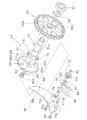
本発明の一実施形態による両軸受リール100は、図1及び図2に示すように、釣り糸を前方に繰り出すレバードラグ型のものである。両軸受リール100は、ハンドル3と、揺動軸76(図3参照)を有するリール本体1と、駆動軸31と、第2ワンウェイクラッチ63と、スプール4と、とを備える。第2ワンウェイクラッチ63は、図3に示すように、ラチェットホイール65と、爪部材66と、爪部材66の揺動制御用の爪揺動制御部67と、を有する。
A double-
<ハンドル及びリール本体の構成>
リール本体1は、図1及び図2に示すように、フレーム10と、フレーム10の両側方を覆う第1側カバー13a及び第2側カバー13bと、を有する。フレーム10は、左右1対の第1側板11a及び第2側板11bと、第1側板11a及び第2側板11bを連結する複数の連結部12とを有する。またリール本体1は、図3に示すように、第2ワンウェイクラッチ63の爪部材66を支持するための爪支持部68を有する。図1及び図2に示すように、第1側板11a及び第2側板11bは側面視略円形の部材であり、第2側板11bの径は第1側板11aの径より大径になるように形成される。複数の連結部12は、第1側板11a及び第2側板11bと一体に形成されており、下側の連結部12は、リールを釣り竿RDに装着するための前後に長い金属製の竿装着脚部7が固定される。
<Structure of handle and reel body>
As shown in FIGS. 1 and 2, the
竿装着脚部7には、釣り竿RDを挟むロッドクランプ8が対向して配置される。ロッドクランプ8は、円弧部8aと円弧部8aの両側から延びる1対の取付部8b,8bとを有する金属製のものである。ロッドクランプ8は、釣り竿RDを挟んだ状態で、第1及び第2締結具9a,9bにより下側の連結部12に固定される。
A
第1側カバー13aは、第1側板11aの側方に装着される側面視略円形の部材である。第2側カバー13bは、第2側板11bの側方に装着される筒状部14と、筒状部14の軸方向外方(図2右側)に突出する膨出部15とを有する。第1側カバー13a及び筒状部14は、それぞれ第1及び第2側板11a,11bと略同径の側面視略円形の部材であり、第2側カバー13bの径は第1側カバー13aの径より大径になるように形成される。
The
筒状部14は、第2側板11bの側方に装着される側面視略円形の部材である。膨出部15は、筒状部14と一体成形され、内部に筒状部14と連通する空間を有するように軸方向外方(図2右側)に突出して形成される。膨出部15は、小円弧部と大円弧部とを有する側面視略雨滴形状の部材であり、下部の大円弧部が筒状部14より下方に突出するように形成される。膨出部15には、ドラグ操作部材2及びハンドル3が外方に露出するように装着される。
The
図2に示すように、膨出部15のドラグ操作部材2の下方には、駆動軸31の装着用の突出筒16が外方に突出して形成される。突出筒16の内部には、スプール4の回転軸であるスプール軸5に平行に筒状の駆動軸31が配置される。
As shown in FIG. 2, a protruding
爪支持部68は、図3に示すように、膨出部15に固定される固定ブラケット75と、爪部材66を揺動自在に支持するための揺動軸76と、を有する。固定ブラケット75は、第2ワンウェイクラッチ63のラチェットホイール65を挟んで第2側カバー13bの膨出部15の内側面に例えば、ねじ部材90により固定される。揺動軸76は、固定ブラケット75に装着され爪部材66を揺動自在に支持する。固定ブラケット75は、ラチェットホイール65を抜け止めするための後述する抜け止めボルト69の頭部69aを露出させるために、三日月形に形成される。これより、固定ブラケット75を膨出部15に固定した後に抜け止めボルト69を締め付けることができる。固定ブラケット75には、揺動軸76をカシメ固定するための第1固定孔75aと、爪部材66の揺動を規制する規制ピン71をカシメ固定するための第2固定孔75bとが形成される。また、爪部材66の固定ブラケット75側へのたわみを防止するためのたわみ防止突起75cが爪部材66に向けて突出して形成される。
As shown in FIG. 3, the
揺動軸76は、例えば、アルミニウム又はステンレス等の金属製のピン部材である。揺動軸76は、図5及び図6に示すように大径の鍔部76aと、固定ブラケット75にかしめ固定されるかしめ部76bと、鍔部76aを挟んでかしめ部76bと逆側に設けられる揺動支持部76cと、を有する。揺動軸76の揺動支持部76cに後述する連動ギア72が回動自在に装着される。連動ギア72は、第1回転部材であり、揺動軸76の揺動支持部76cに連動ギア72を介して爪部材66が揺動自在に支持される。
The
ハンドル3は、図2に示すように、駆動軸31の他方の端部に一体的に回転可能に連結される。ハンドル3は、駆動軸31の先端に連結されたハンドルアーム40と、ハンドルアーム40の先端に回動自在に支持されたハンドル把手41とを有する。ハンドルアーム40は、ねじ部材42により駆動軸31の先端に駆動軸31に対して一体的に回転可能に連結される。ハンドル把手41は、力を入れて握りやすくするために、外形が丸みを帯びた略T字形状になるように形成される。この実施形態のハンドル3は、ハンドル把手41が一つのシングルハンドル型である。なお、ハンドルは、ハンドルアームの両端にハンドル把手が装着されるダブルハンドル型でもよい。
As shown in FIG. 2, the
<駆動軸の構成>
駆動軸31は、図2及び図3に示すように、突出筒16の両端に配置された2つの軸受32、33により突出筒16に回転自在に片持ち支持されており、一方の軸端は軸受32よりも内側に突出して配置される。駆動軸31の軸受32側の突出部には、駆動ギア60が回転自在に装着される。駆動ギア60は、第2回転部材の一例である。駆動ギア60の円板部には、図3に示すように、1対の回転伝達孔60aが形成される。駆動ギア60は、ワッシャ59を介して軸受32に接触する。駆動軸31の他方の軸端には、ハンドル3が回転不能に装着される。駆動軸31の軸受32側の軸端部31bには、断面が例えば矩形などの非円形に形成された回転係止部31aが形成される。軸受32、33の間には、図2に示すように、ローラ型の第1ワンウェイクラッチ62が配置される。第1ワンウェイクラッチ62は、駆動軸31の糸巻き取り方向R1の正転だけを許容し糸繰り出し方向R2の逆転を禁止する。駆動ギア60は、ハンドル3の回転に応じてスプール4を糸巻き取り方向R1に回転するために設けられる。駆動ギア60は、スプール軸5回りに回転自在に装着されたピニオンギア61に噛み合う。
<Configuration of drive shaft>
As shown in FIGS. 2 and 3, the
<第2ワンウェイクラッチの構成>
第2ワンウェイクラッチ63は、図3及び図4に示すように、爪式のものであり、駆動軸31の一方の軸端に配置される。第2ワンウェイクラッチ63は、第1ワンウェイクラッチ62と同様に駆動軸31の逆転を禁止するものである。これらの第1ワンウェイクラッチ62及び第2ワンウェイクラッチ63は、主にスプール4の糸繰り出し方向R2の回転を制動する後述するドラグ機構6を動作させるために使用される。第1ワンウェイクラッチ62は、逆転禁止動作の切り換え時間は速いが、許容伝達トルクが小さい。第2ワンウェイクラッチ63は、切り換え時間は遅いが、許容伝達トルクが大きい。
<Configuration of the second one-way clutch>
As shown in FIGS. 3 and 4, the second one-way clutch 63 is of a claw type and is disposed at one shaft end of the
第2ワンウェイクラッチ63は、図3に示すように、ラチェットホイール65と、爪部材66と、爪部材66の揺動を制御する爪揺動制御部67と、を有する。ラチェットホイール65は、駆動軸31の回転係止部31aに駆動ギア60と連動するように隙間を開けて並べて配置される。爪部材66は、ラチェットホイール65の外周側に配置される。爪揺動制御部67は、爪部材66の揺動を駆動軸31の回転方向に応じて制御する。
Second one-way clutch 63, as shown in FIG. 3 includes a
<ラチェットホイールの構成>
ラチェットホイール65は、例えば、ステンレス又はアルミニウムなどの金属製の部材である。ラチェットホイール65は、外周部に周方向に間隔を隔てて配置された複数の鋸歯状のラチェット歯65aを有する。ラチェットホイール65は、駆動ギア60よりも小径の略円板状の部材であり、中心部に駆動軸31の回転係止部31aに一体的に回転可能に係合する矩形の装着孔65bが形成される。円板部には、両側面を貫通する1対の回転伝達孔65cが駆動ギア60の回転伝達孔60aに対向可能な位置に形成される。この両回転伝達孔60a,65cを連結する連結ピン70が駆動ギア60とラチェットホイール65との間に配置され、両回転伝達孔60a,65cに挿入される。このような構成により、ラチェットホイール65の回転、すなわち駆動軸31の回転が連結ピン70を介して駆動ギア60に伝達される。ラチェットホイール65は、駆動軸31の軸端部31bにねじ込まれる抜け止めボルト69によって抜け止めされ、駆動軸31に一体的に回転可能に装着される。抜け止めボルト69は、ラチェットホイール65を介して駆動ギア60を押圧し、駆動ギア60は、ワッシャ59を介して軸受32の内輪に接触する。このため、駆動ギア60は、抜け止めボルト69によって駆動軸31に軸方向に位置決めされる。
<Ratchet wheel configuration>
The
<爪部材の構成>
爪部材66は、例えば、ステンレス又はアルミニウムなどの金属製の部材である。爪部材66は、図4に示すように、先端部66bがラチェット歯65aに接触して係合する実線で示す係合位置と、先端部66bがラチェット歯65aから離反する二点鎖線で示す離反位置と、に揺動軸76回りに揺動可能である。爪部材66が係合位置に配置されると、駆動軸31の糸繰り出し方向R2の回転が禁止される。したがって、スプール4が糸繰り出し方向R2に回転すると、後述するドラグ機構6が作動する。図5及び図6に示すように、爪部材66は、連動ギア72の後述する円筒部72bに嵌合する支持孔66aを有する。支持孔66aから径方向に延びる爪部材66の先端部66bは、支持孔66aよりもラチェットホイール65の糸巻き取り方向R1の下流側に配置される。爪部材66は、規制ピン71によって離反位置よりもラチェットホイール65から離反しないように規制される。
<Configuration of claw member>
The
<爪揺動制御部の構成>
図5及び図6に示すように、爪揺動制御部67は、連動ギア72と、駆動ギア60と、付勢部材78と、爪カバー80と、を備える。連動ギア72は、第1回転部材の一例である。駆動ギア60は、ハンドル3の回転をスプール4に伝達する機能と、爪揺動制御部67の第2回転部材として駆動軸31に連動して回転する機能と、を有する。
<Configuration of claw swing control unit>
As shown in FIGS. 5 and 6, the claw
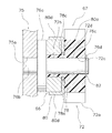
連動ギア72は、例えば、ポリアセタール樹脂、又はポリアミド樹脂等の合成樹脂製の部材である。なお,連動ギア72が金属製であってもよい。連動ギア72は、揺動軸76に回転自在に支持される。連動ギア72は、駆動ギア60に噛み合うギア部72aと、ギア部72aよりも小径に形成された円筒部72bと、を有する。円筒部72bの外周面には、爪部材66が揺動自在に装着される。円筒部72bの軸方向の長さは、爪部材66の厚みと爪カバー80の厚みとを足した長さと同じか僅かに短い。円筒部72bのギア部72a側の外周面には、付勢部材78の後述する摩擦係合部78aを装着するための環状の保持凹部72d(図6参照)が形成される。保持凹部72dの底部は、円筒部72bの外周面と実質的に同じ径方向位置に配置される。連動ギア72の内周部には、ギア部72aと円筒部72bとを貫通する支持孔72cが形成される。この支持孔72cに揺動軸76の揺動支持部76cが嵌合する。
The interlocking
連動ギア72は、揺動軸76の揺動支持部76cの先端に装着される抜け止め部材82によって、爪部材66とともに揺動支持部76cに対して抜け止めされる。抜け止め部材82は、例えばC型止め輪又はE型止め輪などの止め輪を用いることができる。また、ボルトなどのねじ部材を抜け止め部材として用い、ねじ部材を揺動支持部76cの先端面にねじ込んで抜け止めしてもよい。抜け止め部材82は、揺動支持部76cの先端に形成された環状溝76dに装着される。連動ギア72を抜け止め部材82によって抜け止めすることによって、付勢部材78と連動ギア72との接触を確保して付勢部材78を連動ギア72の回転に応じて揺動させることができる。
The interlocking
付勢部材78は、例えば、金属製のばね鋼線を湾曲及び屈曲して形成されたばね部材である。付勢部材78は、連動ギア72と摩擦係合する摩擦係合部78aと、爪部材66を一体的に揺動可能な揺動部78bと、を有する。摩擦係合部78aは、連動ギア72の円筒部72bの保持凹部72dに摩擦係合して装着される円弧部78cを有する。円弧部78cは、揺動部78bから糸繰り出し方向R2に沿って揺動部78bに近接する位置まで概ね円形に湾曲する。揺動部78bは、円弧部78cの端部から爪部材66へ延設された延設部78dを有する。延設部78dは、円弧部78cの径方向外側に向かって延びる。このように付勢部材78を構成すると、連動ギア72が糸巻取方向R1に回転すると、内径が拡がる方向に円弧部78cが弾性変形し、連動ギア72が糸繰り出し方向R2に回転すると、内径が狭まる方向に円弧部78cが弾性変形し、連動ギア72の保持凹部72dに強く接触し摩擦力が強くなる。このため、連動ギア72が糸繰り出し方向R2に回転すると、付勢部材78が連動ギア72に追随して係合位置側に迅速に揺動する。
The biasing
爪カバー80は、爪部材66に一体的に揺動可能に設けられ、延設部78dに係合する。爪カバー80は、付勢部材78の連動ギア72の回転方向に応じた揺動を爪部材66に伝達するために設けられる。爪カバー80は、係合部材の一例である。爪カバー80は、揺動軸76に揺動可能な装着部80aと、爪部材66に一体的に揺動可能に係合する係合部80bと、延設部78dに係合する係合溝80cと、を有する。装着部80aは、円筒部72bにおいて付勢部材78の円弧部78cの外周側に装着される。係合部80bは、装着部80aから爪部材66に沿って延びる。係合部80bは、爪部材66の両側面に係合する一対の係合片80dを有する。係合溝80cは、係合部80bに爪部材66に沿って形成される。係合溝80cには、付勢部材78の延設部78dが配置される。
The
このように構成された第2ワンウェイクラッチ63では、ハンドル3の糸巻き取り方向の回転によって駆動軸31が図4時計回りの糸巻き取り方向R1に回転すると、連動ギア72は、図5反時計回りの糸巻き取り方向R1に回転する。連動ギア72の糸巻き取り方向R1の回転によって、連動ギア72に摩擦係合する付勢部材78が図5反時計回りに揺動し、爪カバー80を介して爪部材66を図5反時計回りに揺動させる。これによって、爪部材66が係合位置から離反位置に向けて揺動する。爪部材66が規制ピン71に接触すると、付勢部材78によって係合位置から離反する方向に付勢された状態で爪部材66が離反位置で静止する。この結果、糸巻き取り時に爪部材66がラチェットホイール65に衝突しなくなり、第2ワンウェイクラッチ63の静音化を図れる。
In the second one-way clutch 63 constructed as described above, when the
仕掛けにかかった獲物の引きが強くなり、駆動軸31が図4反時計回りの糸繰り出し方向R2に回転すると、連動ギア72は、図5時計回りの糸繰り出し方向R2に回転する。連動ギア72の糸繰り出し方向R2の回転によって、連動ギア72に摩擦係合する付勢部材78が図5時計回りに揺動し、爪カバー80を介して爪部材66を図5時計回りに揺動させる。これによって、爪部材66が離反位置から係合位置に揺動する。この結果、糸繰り出し時に爪部材66がラチェットホイール65に接触し、第2ワンウェイクラッチ63が駆動軸31の糸繰り出し方向の逆転を禁止する。これによって、ドラグ機構6が作動し、スプール4の糸繰り出し方向の回転が制動される。ここでは、第2ワンウェイクラッチ63に設けられる爪揺動制御部67において、板状の部材でなく、駆動軸31の回転に応じて回転する連動ギア72によって、爪部材66の揺動を制御するので、揺動制御用の連動ギア72の変形が生じにくくなり、変形によって生じる摩擦力の変化を抑えることができる。
Pull prey afflicted with tackle becomes strong, the driving
<スプールの構成>
スプール4は、図2に示すように、筒状の糸巻胴部4aと、糸巻胴部4aの両側に形成され糸巻胴部4aより大径の第1フランジ部4b及び第2フランジ部4cとを有する。スプール4は軸受20a、20bによりスプール軸5に回転自在に支持される。また、スプール4のハンドル3側には、スプール4の糸繰り出し方向R2の回転を制動するドラグ機構6が設けられている。また、スプール4の第1側カバー13a側には、スプール4を制動する遠心制動機構18が設けられている。遠心制動機構18は、いわゆるバックラッシュと呼ばれるスプール4の過回転により生じるスプール4上での糸ふけを防止するために設けられている。また、スプール4と第1側カバー13aとの間にはスプール発音機構19が設けられている。スプール発音機構19はスプール4の回転に応じて発音する発音状態と発音しない無音状態とに切り換え可能である。
<Spool configuration>
As shown in FIG. 2, the
第2フランジ部4cは、図2に示すように、第1フランジ部4bより大径となるように形成される。第2フランジ部4cは、糸巻胴部4a側がドラグ機構6を構成する後述する第1制動部材25より小径となるように形成された円筒状の小径部4dと、最外周側が第1制動部材25より大径となるように形成された円筒状の大径部4eとを有する。小径部4dは、大径部4eより小径になるように大径部4eと一体成形され、大径部4eと糸巻胴部4aの端部との間に段差を生成するように設けられている。ここでは、糸巻胴部4aの外周に釣り糸を巻き付けていくが、小径部4dの段差により小径部4dの最外径まで釣り糸を巻き付けることが可能である。また、第2側板11bは、大径部4eと小径部4dとの間を覆うように配置されており、その先端部は小径部4dに近接するように径方向内方に延びている。このため、小径部4dより外周に釣り糸が巻き付けられるのを防止できるとともに、釣り糸が軸方向外方へ移動するのを規制できる。
As shown in FIG. 2, the
<ドラグ機構の構成>
ドラグ機構6は、図2に示すように、スプール軸5に装着されたスプール4の糸繰り出し方向R2への回転に加えられる制動力を変更、調整するためのものである。ドラグ機構6は、ドラグ操作部材2と、ドラグ操作部材2の内周部に設けられた第1カム部材21と、第1カム部材21に接触して配置された第2カム部材22と、第2カム部材22に相対回転可能に装着されスプール軸5を外方(図2右側)に引っ張るドラグ調整部材27と、ドラグ調整部材27を第2カム部材22に対して軸方向に抜け止めする抜け止め部材23と、スプール4を軸方向内方に付勢する例えば4枚の皿ばねからなる第1付勢部材24a(図2参照)及びコイルばねからなる第2付勢部材24bと、ドラグ調整部材27を軸方向外方(図2右側)に付勢するコイルばねからなる第3付勢部材24cと、スプール4の軸方向外方(図2右側)に固定された第1制動部材25と、第1制動部材25が接触可能に配置された第2制動部材26とを有する。なお、図2に示すドラグ調整部材27では、スプール軸5の上半分が最大ドラグ作動時の軸方向位置を示し、下半分がドラグ力減少位置を示す。
<Configuration of drag mechanism>
As shown in FIG. 2, the drag mechanism 6 is for changing and adjusting the braking force applied to the rotation of the
ドラグ調整部材27は、有底筒状のキャップ部材であり、ドラグ力を初期設定するための調整部材である。ドラグ調整部材27は、第2カム部材22に相対回転可能に装着され、第2側カバー13bから外方に突出したスプール軸5の端部が螺合し、螺合方向の回転によってスプール軸5を軸方向外方(図2右側)に引っ張る部材である。ドラグ調整部材27の内周部には、雌ねじ部が形成されており、スプール軸5の端部に形成された雄ねじ部が螺合する。ドラグ調整部材27の内周部と、第2カム部材22内周部の軸方向端面との間には、コイルばねからなる第3付勢部材24cが装着されており、ドラグ調整部材27を常に外方に付勢する。これにより、第2カム部材22のがたつきを防止できる。
The
スプール軸5は、図2に示すように、リール本体1に軸方向移動可能かつ相対回転不能に支持された軸部材である。スプール軸5の外周には、スプール4を回転自在に装着するための軸受20a、20bと、後述する第2制動部材26を回転可能に支持するための軸受20cが装着される。軸受20a、20bの間のスプール軸5外周には、図2に示すように、スプール4を軸方向内方(図2左側)に付勢するコイルばねからなる第2付勢部材24bが装着される。また、軸受20aの軸方向内方(図2左側)のスプール軸5外周には、図2に示すように、スプール4を軸方向内方(図2左側)に付勢する皿ばねからなる第1付勢部材24aが装着される。第1付勢部材24aは、第2付勢部材24bに比して付勢力が強くなっている。このため、スプール軸5が軸方向に移動すると、まず第1付勢部材24aが作用し、次に第2付勢部材24bが作用するようになっている。
As shown in FIG. 2, the
また、第2側カバー13bの内周部には軸受20dが装着されており、スプール軸5外周に装着されたピニオンギア61の外周部を支持する。ピニオンギア61は、駆動軸31に一体的に回転可能に連結された駆動ギア60と噛み合っている。ピニオンギア61の先端部は後述する第2制動部材26の内周側に一体的に回転可能に連結される。この結果、ハンドル3からの回転は駆動ギア60、ピニオンギア61、第2制動部材26を介して第1制動部材25に伝達され、第1制動部材25からスプール4に伝達され、スプール4が回転する。
A
第1制動部材25は、図2に示すように、第2側板11bの内部において、スプール4の軸方向外方(図2右側)に一体的に回転可能に連結される環状部材である。第1制動部材25は、スプール4の糸巻き可能径である第2フランジ部4cの小径部4dより大径になるように形成される。第1制動部材25は、スプール4の端面に複数のねじ部材によって固定される。第1制動部材25は、例えばカーボン繊維の織布にフェノール樹脂等の耐熱樹脂を含浸させた繊維強化樹脂等の耐熱合成樹脂製である。第2制動部材26は、ピニオンギア61、軸受20dを介して、リール本体1により軸方向外方(図2右側)への移動が規制される。
First braking member 25, as shown in FIG. 2, in the inside of the
第1及び第2制動部材25,26の外方は、カバー円板28により覆われている。カバー円板28の外周部は、第2フランジ部4cの大径部4eの軸方向外方(図2右側)の先端部に固定される。カバー円板28は、第2フランジ部4cの大径部4eの先端部にねじ部材により固定される。
The outer sides of the first and
このように構成された両軸受リール100では、釣りを行うときには、ドラグ機構6のドラグ操作部材2を制動解除位置側に操作し、スプール4を自由回転可能の状態にしてキャスティングを行う。これにより、仕掛けの自重によってスプール4が糸繰り出し方向に回転し、釣り糸がスプールから放出される。このとき、第1制動部材25と第2制動部材26とが離反しているため、駆動軸31は糸繰り出し方向には回転しない。仕掛けが着水すると、ドラグ操作部材2によって所望のドラグ力にセットして獲物が仕掛けにかかるのを待つ。仕掛けに獲物がかかって設定したドラグ力よりも強い力で獲物が釣り糸を引っ張ると、駆動軸31が糸繰り出し方向R2に回転する。これによって、連動ギア72が糸繰り出し方向に回転し、付勢部材78が爪部材66を離反位置から係合位置に付勢する。これによって、爪部材66がラチェットホイール65のラチェット歯65aに接触してラチェットホイール65の糸繰り出し方向R2の回転を阻止する。この結果、ドラグ機構6が作動して釣り糸に過大な力が作用しなくなる。ここでは、第2ワンウェイクラッチ63に設けられる爪揺動制御部67において、板状の部材でなく、駆動軸31の回転に応じて回転する連動ギア72によって、爪部材66の揺動を制御するので、揺動制御用の連動ギア72の変形が生じにくくなり、変形によって生じる摩擦力の変化を抑えることができる。
In the double-
<他の実施形態>
以上、本発明の一実施形態について説明したが、本発明は上記実施形態に限定されるものではなく、発明の要旨を逸脱しない範囲で種々の変更が可能である。特に、本明細書に書かれた複数の実施形態及び変形例は必要に応じて任意に組合せ可能である。
<Other embodiments>
As mentioned above, although one Embodiment of this invention was described, this invention is not limited to the said embodiment, A various change is possible in the range which does not deviate from the summary of invention. In particular, a plurality of embodiments and modifications described in this specification can be arbitrarily combined as necessary.
(a)上記実施形態では、中型のレバードラグ型の両軸受リールに本発明を採用したが、両軸受リールの駆動軸の軸端にラチェットホイールが装着される全てのワンウェイクラッチに本発明を適用できる。例えば、駆動軸の周囲にドラグ機構が配置されるスタードラグ機構を有する両軸受リールに採用される爪式のワンウェイクラッチにも本発明を適用できる。 (A) In the above embodiment, the present invention is applied to a medium-sized lever drag type dual-bearing reel. However, the present invention is applied to all one-way clutches in which a ratchet wheel is mounted on the shaft end of the drive shaft of the dual-bearing reel. it can. For example, the present invention can also be applied to the one-way clutch claw type employed in dual-bearing reel having a star drag mechanism drag mechanism is disposed around the drive shaft.
(b)上記実施形態では、駆動ギアの回転を第1回転部材である連動ギア72に直接伝達したが、間に別の回転部材を設けてもよい。
(B) In the above embodiment, the rotation of the drive gear is directly transmitted to the interlocking
(c)上記実施形態で、駆動軸の回転を第2回転部材である駆動ギアを介して第1回転部材である連動ギアに伝達したが、本発明はこれに限定されない。例えば、駆動軸の回転を第1回転部材に直接伝達してもよい。例えば、第1回転部材としてゴムローラを用い、ゴムローラを駆動軸の外周面に接触させて駆動軸の回転をゴムローラに伝達してもよい。 (C) In the above embodiment, the rotation of the drive shaft is transmitted to the interlocking gear that is the first rotating member via the driving gear that is the second rotating member, but the present invention is not limited to this. For example, the rotation of the drive shaft may be directly transmitted to the first rotating member. For example, a rubber roller may be used as the first rotation member, and the rotation of the drive shaft may be transmitted to the rubber roller by bringing the rubber roller into contact with the outer peripheral surface of the drive shaft.
(d)上記実施形態で、第2回転部材として駆動ギアを例示したが本発明に係る第2回転部材はこれに限定されない。例えば、駆動軸又は駆動軸と連動して回転する部材に駆動ギアとは別に第2回転部材を設けてもよい。また、レバードラグ型の両軸受リールにおいて、ラチェットホイールが、駆動軸と連動して回転するドラグディスク又はスプール軸に一体的に回転可能に設けられる場合、第2回転部材は、ドラグディスク又はスプール軸に一体的に回転可能に設けられてもよい。この場合には、第2回転部材は、第1回転部材に噛み合うギア部材であるのが好ましい。 (D) In the said embodiment, although the drive gear was illustrated as a 2nd rotation member, the 2nd rotation member which concerns on this invention is not limited to this. For example, a second rotating member may be provided separately from the driving gear on the driving shaft or a member that rotates in conjunction with the driving shaft. Further, in the lever drag type dual-bearing reel, when the ratchet wheel is provided so as to be integrally rotatable with the drag disk or the spool shaft that rotates in conjunction with the drive shaft, the second rotating member is the drag disk or the spool shaft. May be provided so as to be integrally rotatable. In this case, the second rotating member is preferably a gear member that meshes with the first rotating member.
(e)上記実施形態では、第1回転部材及び第2回転部材としてギアを例示したが本発明はこれに限定されない。第1回転部材及び第2回転部材は、ベルトで連結されたプーリでもよいし、摩擦によって動力が伝達される摩擦車でもよい。 (E) In the said embodiment, although the gear was illustrated as a 1st rotation member and a 2nd rotation member, this invention is not limited to this. The first rotating member and the second rotating member may be a pulley connected by a belt, or a friction wheel to which power is transmitted by friction.
(f)上記実施形態では、ラチェットホイール65と駆動ギア60とを連結ピンで連結したが、連結せずに駆動ギア60を駆動軸31に一体的に回転可能に装着してもよい。また、連結した場合、ラチェットホイール65を駆動軸31に回転自在に装着し、駆動ギア60から回転が伝達されるように構成してもよい。
(F) In the above-described embodiment, the
(g)上記実施形態では、爪部材の揺動制御を確実に行うために、付勢部材を第1回転部材と爪部材との間に配置したが、本発明はこれに限定されない。第1回転部材と爪部材とを直接接触させて摩擦によって爪部材を係合位置と離反位置とに揺動制御してもよい。 (G) In the embodiment described above, the biasing member is disposed between the first rotating member and the claw member in order to perform the swing control of the claw member with certainty, but the present invention is not limited to this. The first rotating member and the claw member may be brought into direct contact and the claw member may be controlled to swing between the engagement position and the separation position by friction.
(h)上記実施形態では、爪部材66に爪カバー80を装着し、爪カバー80に付勢部材78を係合させたが本発明はこれに限定されない。付勢部材を爪部材に直接係合するように構成してもよい。この場合、例えば、爪部材に付勢部材の揺動部に係合する凹部又は凸部を設けてもよい。
(H) In the above embodiment, the
(i)上記実施形態では、第1回転部材に円筒部を形成し、円筒部を介して爪部材を揺動軸に揺動可能に装着したが、本発明はこれに限定されない。爪部材を揺動軸に直接揺動可能に装着してもよい。 (I) In the above embodiment, a cylindrical portion is formed on the first rotating member, and the claw member is swingably attached to the swing shaft via the cylindrical portion. However, the present invention is not limited to this. The claw member may be mounted on the swing shaft so as to be swingable directly.
<特徴>
上記実施形態は、下記のように表現可能である。
<Features>
The above embodiment can be expressed as follows.
(A)両軸受リール100は、釣り糸を前方に繰り出すリールである。両軸受リール100は、ハンドル3と、リール本体1と、駆動軸31と、ラチェットホイール65と、爪部材66と、スプール4と、爪揺動制御部67と、を備える。リール本体1は、揺動軸76が設けられ、ハンドル3が側部に配置されるものである。駆動軸31は、リール本体1に回転自在に装着され、ハンドル3に連動して回転可能である。ラチェットホイール65は、周方向に間隔を隔てて配置された複数のラチェット歯65aを有する。ラチェットホイール65は、駆動軸31に連動して回転可能である。爪部材66は、ラチェット歯65aに係合する係合位置とラチェット歯65aから離反する離反位置とに揺動可能に揺動軸76に設けられる。スプール4は、リール本体1に対して回転可能であり、駆動軸31の糸巻き取り方向R1の回転によって釣り糸を巻き取り可能である。爪揺動制御部67は、揺動軸76に回動自在に設けられ、駆動軸31の回転に応じて回転する連動ギア72を有し、連動ギア72の回転方向に応じて、爪部材66を係合位置及び離反位置に揺動させる。
(A) The double-
この両軸受リールでは、駆動軸31が糸巻き取り方向R1に回転すると爪揺動制御部67の揺動制御用の連動ギア72も糸巻き取り方向R1に回転する。連動ギア72が糸巻き取り方向R1に回転すると、例えば、爪部材を離反位置に揺動させる。一方、駆動軸が糸繰り出し方向R2に回転すると、連動ギア72も糸繰り出し方向R2に回転する。連動ギア72が糸繰り出し方向R2に回転すると、例えば、爪部材66を係合位置に揺動させる。これによって、ラチェットホイールの糸繰り出し方向R2の回転が禁止され、駆動軸31も糸繰り出し方向R2の回転が禁止される。この結果、ドラグ機構を動作させることができる。ここでは、板状の部材でなく、駆動軸31の回転に応じて回転する連動ギア72によって、爪部材66の揺動を制御するので、揺動制御用の部材である連動ギア72の変形が生じにくくなり、変形によって生じる摩擦力の変化を抑えることができる。
In the dual-bearing reel, when the
(B)爪揺動制御部67は、駆動軸31と連動して回転可能な駆動ギア60をさらに有してもよい。連動ギア72は、駆動ギア60の回転に連動して回転する。この場合には、駆動ギア60を介して駆動軸31の回転を連動ギア72に伝達できるので、ラチェットホイール65が両軸受リール100内のどのような場所に配置されても、連動ギア72を駆動軸31に連動して回転させることができる。
(B) The claw
(C)第2回転部材である駆動ギア60は、駆動軸31に設けられてもよい。この場合には、ラチェットホイール65が駆動軸31に設けられる場合に、駆動軸31の回転を容易に連動ギア72に伝達できる。また、ラチェットホイール65と、駆動軸31の回転をスプール4に伝達する駆動ギア60と、の大きさ又は位置関係に限定されずに連動ギア72を配置できる。
(C) The
(D)第2回転部材は、駆動軸31に設けられ、ハンドル3の回転をスプール4に伝達するための駆動ギアであってもよい。この場合には、駆動軸31の回転を連動ギア72に伝達するための第2回転部材と駆動ギアとを兼用できるので、爪揺動制御部67の構成が簡素になる。
(D) The second rotation member may be a drive gear that is provided on the
(E)爪揺動制御部67は、連動ギア72の回転方向に応じて爪部材66を係合位置と離反位置とに付勢する付勢部材78をさらに有してもよい。この場合には、連動ギア72が爪部材66を直接揺動制御するのではなく、付勢部材78を介して連動ギア72が爪部材66を揺動制御するので、爪部材66を精度良く揺動制御できる。
(E) The claw
(F)付勢部材78は、連動ギア72と摩擦係合する摩擦係合部78aと、爪部材66を一体的に揺動可能な揺動部78bと、を有してもよい。この場合には、付勢部材78が摩擦係合部78aと揺動部78bとを有するので、付勢部材78によって、爪部材66をより精度良く揺動制御できる。
(F) The urging
(G)連動ギア72は、揺動軸76の周囲に円筒状に設けられ、付勢部材78が装着される円筒部72bを有してもよい。この場合には、爪部材66が連動ギア72を介して揺動軸76に装着されるので、爪部材66と連動ギア72の接触面積が大きくなり、爪部材66が連動ギア72の回動に応じてさらに揺動しやすくなる。
(G) The interlocking
(H)付勢部材78の摩擦係合部78aは、円筒部72bに摩擦係合して装着される円弧部78cを有し、付勢部材78の揺動部78bは、円弧部78cの端部から爪部材66へ延設された延設部78dを有してもよい。この場合には、円弧部78cに連動ギア72と摩擦係合し、延設部78dで爪部材66を揺動制御することができる。
(H) The
(I)円筒部72bは、その円周に付勢部材78を保持する保持凹部72dを有してもよい。この場合には、付勢部材78を連動ギア72の保持凹部72dに保持させることができるので、付勢部材78が連動ギア72の回転に応じて揺動しやすくなる。
(I) The
(J)爪揺動制御部67は、爪部材66に一体的に揺動可能に設けられ、延設部78dに係合する爪カバー80をさらに有する。この場合には、付勢部材78の延設部78dによって爪カバー80を介して爪部材66を揺動させることができるので、爪部材66を連動ギア72の回転に応じてさらに確実に揺動させることができる。
(J) The claw
(K)爪カバー80は、揺動軸76に装着可能な装着部80aと、爪部材66に一体的に揺動可能に係合する係合部80bと、延設部78dに係合する係合溝80cと、を有してもよい。この場合には、係合部80bが爪部材66に係合し、付勢部材78の延設部78dが係合溝80cに係合するので、付勢部材78の揺動を爪部材66に確実に伝達できる。
(K) The
(L)装着部80aは、円筒部72bにおいて円弧部78cの外周側に装着され、係合部80bは、装着部80aから爪部材66に沿って延び、爪部材66の両側面に係合する一対の係合片80dを有してもよい。係合溝80cは、係合部80bに爪部材66に沿って形成され、延設部78dが配置される。この場合には、係合片80dによって爪部材66をはさみ、かつ係合溝80c内に延設部78dが配置されるため、延設部78dが揺動すると係合溝80cを介して爪カバー80を揺動させ、さらに係合部80bを介して爪部材66を揺動させる。このため、付勢部材78の揺動によって爪部材66をさらに確実に揺動させることができる。
(L) The mounting
(M)連動ギア72は、駆動ギア60にかみ合うギア部材であってもよい。この場合には、連動ギア72がギア部材であるので、連動ギア72が駆動ギア60に対して滑らなくなり、駆動ギア60の回転に対して瞬時に連動する。
(M) The interlocking
1 リール本体
3 ハンドル
4 スプール
31 駆動軸
60 駆動ギア(第2回転部材の一例)
65 ラチェットホイール
65a ラチェット歯
66 爪部材
67 爪揺動制御部
72 連動ギア(第1回転部材の一例)
72b 円筒部
72d 保持凹部
76 揺動軸
78 付勢部材
78a 摩擦係合部
78b 揺動部
78c 円弧部
78d 延設部
80 爪カバー(係合部材の一例)
80a 装着部
80b 係合部
80c 係合溝
80d 係合片
DESCRIPTION OF
65
Claims (13)
ハンドルと、
揺動軸が設けられ、前記ハンドルが側部に配置されるリール本体と、
前記リール本体に回転自在に装着され、前記ハンドルに連動して回転可能な駆動軸と、
周方向に間隔を隔てて配置された複数のラチェット歯を有し、前記駆動軸に連動して回転可能なラチェットホイールと、
前記ラチェット歯に係合する係合位置と前記ラチェット歯から離反する離反位置とに揺動可能に前記揺動軸に設けられる爪部材と、
前記リール本体に対して回転可能であり、前記駆動軸の糸巻取方向の回転によって釣り糸を巻き取り可能なスプールと、
前記揺動軸に回動自在に設けられ、前記駆動軸の回転に応じて回転する第1回転部材を有し、前記第1回転部材の回転方向に応じて、前記爪部材を前記係合位置及び前記離反位置に揺動させる爪揺動制御部と、
を備える両軸受リール。 A dual-bearing reel that feeds the fishing line forward,
A handle,
A reel body provided with a swing shaft, and the handle is disposed on the side;
A drive shaft rotatably mounted on the reel body and rotatable in conjunction with the handle;
A ratchet wheel having a plurality of ratchet teeth arranged at intervals in the circumferential direction and rotatable in conjunction with the drive shaft;
A claw member provided on the swing shaft so as to be swingable between an engagement position engaging with the ratchet teeth and a separation position separating from the ratchet teeth;
A spool that is rotatable with respect to the reel body, and capable of winding a fishing line by rotation of the drive shaft in a line winding direction;
A first rotation member that is rotatably provided on the swing shaft and rotates according to the rotation of the drive shaft, and the claw member is moved to the engagement position according to the rotation direction of the first rotation member. And a claw swing control unit that swings to the separated position;
A dual bearing reel.
前記第1回転部材は、前記第2回転部材の回転に連動して回転する、請求項1に記載の両軸受リール。 The claw swing control unit further includes a second rotating member that can rotate in conjunction with the drive shaft,
The dual-bearing reel according to claim 1, wherein the first rotating member rotates in conjunction with the rotation of the second rotating member.
前記第1回転部材と摩擦係合する摩擦係合部と、
前記爪部材を一体的に揺動可能な揺動部と、
を有する、請求項5に記載の両軸受リール。 The biasing member is
A friction engagement portion that frictionally engages with the first rotating member;
A swinging portion capable of swinging the claw member integrally;
The double-bearing reel according to claim 5, wherein
前記付勢部材の前記揺動部は、前記円弧部の端部から前記爪部材へ延設された延設部を有する、請求項7に記載の両軸受リール。 The friction engagement portion of the urging member has an arc portion that is attached by friction engagement with the cylindrical portion,
The swinging portion includes an extending portion which extends into the pawl member from an end portion of the arcuate portion, a dual-bearing reel according to claim 7 of the biasing member.
前記揺動軸に揺動可能な装着部と、
前記爪部材に一体的に揺動可能に係合する係合部と、
前記延設部に係合する係合溝と、を有する、請求項10に記載の両軸受リール。 The engaging member is
A mounting portion swingable on the swing shaft;
An engaging portion engaged with the claw member so as to be swingable integrally;
The double-bearing reel according to claim 10, further comprising an engaging groove that engages with the extending portion.
前記係合部は、前記装着部から前記爪部材に沿って延び、前記爪部材の両側面に係合する一対の係合片を有し、
前記係合溝は、前記係合部に前記爪部材に沿って形成され、前記延設部が配置される、請求項11に記載の両軸受リール。 The mounting portion is mounted on the outer peripheral side of the arc portion in the cylindrical portion,
The engaging portion has a pair of engaging pieces that extend from the mounting portion along the claw member and engage with both side surfaces of the claw member ,
The double-bearing reel according to claim 11, wherein the engaging groove is formed in the engaging portion along the claw member, and the extending portion is disposed.
Priority Applications (6)
| Application Number | Priority Date | Filing Date | Title |
|---|---|---|---|
| JP2013235777A JP6200287B2 (en) | 2013-11-14 | 2013-11-14 | Double bearing reel |
| KR1020140071206A KR102243481B1 (en) | 2013-11-14 | 2014-06-12 | Dual-bearing reel |
| TW103123694A TWI623264B (en) | 2013-11-14 | 2014-07-09 | Double bearing coiler |
| US14/523,766 US9615560B2 (en) | 2013-11-14 | 2014-10-24 | Dual-bearing reel |
| MYPI2014703270A MY171377A (en) | 2013-11-14 | 2014-11-05 | Dual-bearing reel |
| CN201410644021.7A CN104621064B (en) | 2013-11-14 | 2014-11-14 | Double-bearing reel |
Applications Claiming Priority (1)
| Application Number | Priority Date | Filing Date | Title |
|---|---|---|---|
| JP2013235777A JP6200287B2 (en) | 2013-11-14 | 2013-11-14 | Double bearing reel |
Publications (3)
| Publication Number | Publication Date |
|---|---|
| JP2015092876A JP2015092876A (en) | 2015-05-18 |
| JP2015092876A5 JP2015092876A5 (en) | 2016-12-22 |
| JP6200287B2 true JP6200287B2 (en) | 2017-09-20 |
Family
ID=53195726
Family Applications (1)
| Application Number | Title | Priority Date | Filing Date |
|---|---|---|---|
| JP2013235777A Active JP6200287B2 (en) | 2013-11-14 | 2013-11-14 | Double bearing reel |
Country Status (6)
| Country | Link |
|---|---|
| US (1) | US9615560B2 (en) |
| JP (1) | JP6200287B2 (en) |
| KR (1) | KR102243481B1 (en) |
| CN (1) | CN104621064B (en) |
| MY (1) | MY171377A (en) |
| TW (1) | TWI623264B (en) |
Families Citing this family (6)
| Publication number | Priority date | Publication date | Assignee | Title |
|---|---|---|---|---|
| JP6488098B2 (en) * | 2014-10-10 | 2019-03-20 | 株式会社シマノ | Double bearing reel |
| JP6518514B2 (en) * | 2015-05-28 | 2019-05-22 | 株式会社シマノ | Double bearing reel |
| GB201601500D0 (en) * | 2016-01-27 | 2016-03-09 | Belron Hungary Kft Zug Branch | Winder unit for vehicle glazing panel cut out |
| JP7227852B2 (en) * | 2019-05-29 | 2023-02-22 | 株式会社シマノ | fishing reel |
| JP2023002210A (en) * | 2021-06-22 | 2023-01-10 | 株式会社シマノ | One-way clutch unit for fishing reel and fishing reel |
| US20230071449A1 (en) * | 2021-09-07 | 2023-03-09 | TrikaUSA Inc. | Fishing reel axial force distribution |
Family Cites Families (23)
| Publication number | Priority date | Publication date | Assignee | Title |
|---|---|---|---|---|
| US4166594A (en) * | 1976-02-19 | 1979-09-04 | Shakespeare Of Arkansas, Inc. | Variable drive clutch for fishing reel |
| JPS5959777U (en) * | 1982-10-13 | 1984-04-19 | 株式会社シマノ | double bearing reel |
| JPH0246295Y2 (en) * | 1985-05-07 | 1990-12-06 | ||
| US5489070A (en) * | 1985-07-22 | 1996-02-06 | Zebco Corporation | Bait casting fishing reel |
| US4703902A (en) * | 1986-04-29 | 1987-11-03 | Minnesota Mining And Manufacturing Company | Drag mechanism for fly fishing reel |
| JP2922572B2 (en) * | 1990-04-06 | 1999-07-26 | 株式会社シマノ | Transmission for fishing reel |
| US5217182A (en) * | 1991-02-28 | 1993-06-08 | Brunswick Corporation | Bearing assembly for a spool shaft in a bait casting fishing reel |
| JP2551112Y2 (en) * | 1991-05-14 | 1997-10-22 | 株式会社シマノ | Spinning reel reverse rotation prevention mechanism |
| CN2099444U (en) * | 1991-06-07 | 1992-03-25 | 张瑞莹 | Automatic or hand dual-purpose fishing tackle |
| JP3010400U (en) * | 1994-07-11 | 1995-05-02 | ダイワ精工株式会社 | Reverse rotation prevention device for fishing reel |
| JPH09168355A (en) * | 1995-12-21 | 1997-06-30 | Mamiya Op Co Ltd | Cantilever reel for fishing |
| JP4381580B2 (en) * | 2000-08-30 | 2009-12-09 | 株式会社シマノ | Double bearing reel reverse rotation prevention mechanism |
| JP3862229B2 (en) * | 2003-06-25 | 2006-12-27 | 株式会社シマノ | Double bearing reel sound generator |
| JP4451773B2 (en) | 2004-12-27 | 2010-04-14 | 株式会社シマノ | One-way clutch of double-bearing reel |
| KR100613148B1 (en) | 2005-05-09 | 2006-08-17 | 이재구 | Fly reel |
| US7198219B1 (en) * | 2005-05-27 | 2007-04-03 | Harout Alajajyan | Fishing reel transmission |
| JP5159479B2 (en) * | 2008-07-08 | 2013-03-06 | 株式会社シマノ | Double-bearing reel drag mechanism |
| JP5258688B2 (en) * | 2009-07-14 | 2013-08-07 | 株式会社シマノ | Double bearing reel sound generator |
| JP5349349B2 (en) * | 2010-01-25 | 2013-11-20 | 株式会社シマノ | Drag bearing device for dual-bearing reel |
| JP5507374B2 (en) * | 2010-07-26 | 2014-05-28 | 株式会社シマノ | Drag bearing device for dual-bearing reel |
| JP5746841B2 (en) * | 2010-09-22 | 2015-07-08 | 株式会社シマノ | Clutch control device for double bearing reel |
| US8777146B2 (en) | 2012-01-27 | 2014-07-15 | Shimano Inc. | Dual-bearing reel |
| WO2017177325A1 (en) | 2016-04-12 | 2017-10-19 | Abbecan Industries Inc. | Fishing reel |
-
2013
- 2013-11-14 JP JP2013235777A patent/JP6200287B2/en active Active
-
2014
- 2014-06-12 KR KR1020140071206A patent/KR102243481B1/en active IP Right Grant
- 2014-07-09 TW TW103123694A patent/TWI623264B/en active
- 2014-10-24 US US14/523,766 patent/US9615560B2/en active Active
- 2014-11-05 MY MYPI2014703270A patent/MY171377A/en unknown
- 2014-11-14 CN CN201410644021.7A patent/CN104621064B/en active Active
Also Published As
| Publication number | Publication date |
|---|---|
| KR20150056031A (en) | 2015-05-22 |
| US20150201599A1 (en) | 2015-07-23 |
| MY171377A (en) | 2019-10-10 |
| TWI623264B (en) | 2018-05-11 |
| CN104621064B (en) | 2019-10-25 |
| US9615560B2 (en) | 2017-04-11 |
| KR102243481B1 (en) | 2021-04-23 |
| CN104621064A (en) | 2015-05-20 |
| JP2015092876A (en) | 2015-05-18 |
| TW201517790A (en) | 2015-05-16 |
Similar Documents
| Publication | Publication Date | Title |
|---|---|---|
| JP6200287B2 (en) | Double bearing reel | |
| JP2015092876A5 (en) | ||
| CN106172292B (en) | Dual-bearing fishing reel | |
| JP5258688B2 (en) | Double bearing reel sound generator | |
| JP2012024037A5 (en) | ||
| JP2013146201A5 (en) | ||
| CN105265401B (en) | Dual-bearing reel and clutch mechanism for dual-bearing reel | |
| JP2011019427A5 (en) | ||
| JP5242353B2 (en) | Drag adjusting device for double-bearing reel | |
| JP2007006710A (en) | Double bearing reel | |
| JP4451773B2 (en) | One-way clutch of double-bearing reel | |
| JP2016174593A (en) | Spinning reel | |
| JP2014212739A (en) | Dual-bearing reel | |
| JP4381580B2 (en) | Double bearing reel reverse rotation prevention mechanism | |
| JP2006180777A5 (en) | ||
| JP4384936B2 (en) | Double bearing reel | |
| TWI771374B (en) | Fishing reel | |
| JP2006025763A (en) | Handle-assembling body of fishing reel | |
| JPH10210904A (en) | Dragging mechanism for fishing reel | |
| JP7404161B2 (en) | spinning reel | |
| JP4395409B2 (en) | Double-bearing reel drag mechanism | |
| JP6842756B2 (en) | Fishing reel | |
| JP6636748B2 (en) | Spinning reel | |
| JP6856738B2 (en) | Spinning reel | |
| JP6946123B2 (en) | Double bearing reel spool |
Legal Events
| Date | Code | Title | Description |
|---|---|---|---|
| A521 | Request for written amendment filed |
Free format text: JAPANESE INTERMEDIATE CODE: A523 Effective date: 20161101 |
|
| A621 | Written request for application examination |
Free format text: JAPANESE INTERMEDIATE CODE: A621 Effective date: 20161101 |
|
| A521 | Request for written amendment filed |
Free format text: JAPANESE INTERMEDIATE CODE: A523 Effective date: 20161104 |
|
| A977 | Report on retrieval |
Free format text: JAPANESE INTERMEDIATE CODE: A971007 Effective date: 20170727 |
|
| TRDD | Decision of grant or rejection written | ||
| A01 | Written decision to grant a patent or to grant a registration (utility model) |
Free format text: JAPANESE INTERMEDIATE CODE: A01 Effective date: 20170801 |
|
| A61 | First payment of annual fees (during grant procedure) |
Free format text: JAPANESE INTERMEDIATE CODE: A61 Effective date: 20170825 |
|
| R150 | Certificate of patent or registration of utility model |
Ref document number: 6200287 Country of ref document: JP Free format text: JAPANESE INTERMEDIATE CODE: R150 |
|
| R250 | Receipt of annual fees |
Free format text: JAPANESE INTERMEDIATE CODE: R250 |
|
| R250 | Receipt of annual fees |
Free format text: JAPANESE INTERMEDIATE CODE: R250 |
|
| R250 | Receipt of annual fees |
Free format text: JAPANESE INTERMEDIATE CODE: R250 |
|
| S111 | Request for change of ownership or part of ownership |
Free format text: JAPANESE INTERMEDIATE CODE: R313113 |
|
| R350 | Written notification of registration of transfer |
Free format text: JAPANESE INTERMEDIATE CODE: R350 |
|
| R250 | Receipt of annual fees |
Free format text: JAPANESE INTERMEDIATE CODE: R250 |