JP4381580B2 - Double bearing reel reverse rotation prevention mechanism - Google Patents
Double bearing reel reverse rotation prevention mechanism Download PDFInfo
- Publication number
- JP4381580B2 JP4381580B2 JP2000261523A JP2000261523A JP4381580B2 JP 4381580 B2 JP4381580 B2 JP 4381580B2 JP 2000261523 A JP2000261523 A JP 2000261523A JP 2000261523 A JP2000261523 A JP 2000261523A JP 4381580 B2 JP4381580 B2 JP 4381580B2
- Authority
- JP
- Japan
- Prior art keywords
- spool
- reverse rotation
- reel
- dual
- reel body
- Prior art date
- Legal status (The legal status is an assumption and is not a legal conclusion. Google has not performed a legal analysis and makes no representation as to the accuracy of the status listed.)
- Expired - Fee Related
Links
- 230000007246 mechanism Effects 0.000 title claims abstract description 91
- 230000002265 prevention Effects 0.000 title claims description 27
- 230000009977 dual effect Effects 0.000 claims abstract description 20
- 210000000078 claw Anatomy 0.000 claims description 39
- 238000004804 winding Methods 0.000 claims description 32
- 230000002093 peripheral effect Effects 0.000 claims description 12
- 238000000926 separation method Methods 0.000 claims description 8
- 230000036544 posture Effects 0.000 description 24
- 230000005540 biological transmission Effects 0.000 description 4
- 238000012423 maintenance Methods 0.000 description 3
- OKTJSMMVPCPJKN-UHFFFAOYSA-N Carbon Chemical compound [C] OKTJSMMVPCPJKN-UHFFFAOYSA-N 0.000 description 2
- 230000001154 acute effect Effects 0.000 description 2
- 230000007423 decrease Effects 0.000 description 2
- 239000004519 grease Substances 0.000 description 2
- 239000000463 material Substances 0.000 description 2
- 235000013372 meat Nutrition 0.000 description 2
- 239000002184 metal Substances 0.000 description 2
- 238000000034 method Methods 0.000 description 2
- 241000251468 Actinopterygii Species 0.000 description 1
- 208000001840 Dandruff Diseases 0.000 description 1
- 230000009471 action Effects 0.000 description 1
- 229910045601 alloy Inorganic materials 0.000 description 1
- 239000000956 alloy Substances 0.000 description 1
- 238000013459 approach Methods 0.000 description 1
- 229910052799 carbon Inorganic materials 0.000 description 1
- 230000008859 change Effects 0.000 description 1
- 230000008878 coupling Effects 0.000 description 1
- 238000010168 coupling process Methods 0.000 description 1
- 238000005859 coupling reaction Methods 0.000 description 1
- 230000000694 effects Effects 0.000 description 1
- 239000000835 fiber Substances 0.000 description 1
- 229910002804 graphite Inorganic materials 0.000 description 1
- 239000010439 graphite Substances 0.000 description 1
- 239000000314 lubricant Substances 0.000 description 1
- 230000000149 penetrating effect Effects 0.000 description 1
- 230000008569 process Effects 0.000 description 1
- 239000011347 resin Substances 0.000 description 1
- 229920005989 resin Polymers 0.000 description 1
- 239000010935 stainless steel Substances 0.000 description 1
- 229910001220 stainless steel Inorganic materials 0.000 description 1
- 230000009466 transformation Effects 0.000 description 1
- 238000011144 upstream manufacturing Methods 0.000 description 1
- 239000013585 weight reducing agent Substances 0.000 description 1
Images


Classifications
-
- A—HUMAN NECESSITIES
- A01—AGRICULTURE; FORESTRY; ANIMAL HUSBANDRY; HUNTING; TRAPPING; FISHING
- A01K—ANIMAL HUSBANDRY; AVICULTURE; APICULTURE; PISCICULTURE; FISHING; REARING OR BREEDING ANIMALS, NOT OTHERWISE PROVIDED FOR; NEW BREEDS OF ANIMALS
- A01K89/00—Reels
- A01K89/015—Reels with a rotary drum, i.e. with a rotating spool
- A01K89/0155—Antibacklash devices
-
- A—HUMAN NECESSITIES
- A01—AGRICULTURE; FORESTRY; ANIMAL HUSBANDRY; HUNTING; TRAPPING; FISHING
- A01K—ANIMAL HUSBANDRY; AVICULTURE; APICULTURE; PISCICULTURE; FISHING; REARING OR BREEDING ANIMALS, NOT OTHERWISE PROVIDED FOR; NEW BREEDS OF ANIMALS
- A01K89/00—Reels
- A01K89/01—Reels with pick-up, i.e. with the guiding member rotating and the spool not rotating during normal retrieval of the line
- A01K89/0117—Anti-reverse mechanisms
-
- A—HUMAN NECESSITIES
- A01—AGRICULTURE; FORESTRY; ANIMAL HUSBANDRY; HUNTING; TRAPPING; FISHING
- A01K—ANIMAL HUSBANDRY; AVICULTURE; APICULTURE; PISCICULTURE; FISHING; REARING OR BREEDING ANIMALS, NOT OTHERWISE PROVIDED FOR; NEW BREEDS OF ANIMALS
- A01K89/00—Reels
- A01K89/015—Reels with a rotary drum, i.e. with a rotating spool
-
- A—HUMAN NECESSITIES
- A01—AGRICULTURE; FORESTRY; ANIMAL HUSBANDRY; HUNTING; TRAPPING; FISHING
- A01K—ANIMAL HUSBANDRY; AVICULTURE; APICULTURE; PISCICULTURE; FISHING; REARING OR BREEDING ANIMALS, NOT OTHERWISE PROVIDED FOR; NEW BREEDS OF ANIMALS
- A01K89/00—Reels
- A01K89/02—Brake devices for reels
- A01K89/033—Brake devices for reels with a rotary drum, i.e. for reels with a rotating spool
- A01K89/045—Spool bearing brake
-
- A—HUMAN NECESSITIES
- A01—AGRICULTURE; FORESTRY; ANIMAL HUSBANDRY; HUNTING; TRAPPING; FISHING
- A01K—ANIMAL HUSBANDRY; AVICULTURE; APICULTURE; PISCICULTURE; FISHING; REARING OR BREEDING ANIMALS, NOT OTHERWISE PROVIDED FOR; NEW BREEDS OF ANIMALS
- A01K89/00—Reels
- A01K89/02—Brake devices for reels
- A01K89/033—Brake devices for reels with a rotary drum, i.e. for reels with a rotating spool
- A01K89/051—Adjustable pressure pawls, e.g. braking clickers
-
- A—HUMAN NECESSITIES
- A01—AGRICULTURE; FORESTRY; ANIMAL HUSBANDRY; HUNTING; TRAPPING; FISHING
- A01K—ANIMAL HUSBANDRY; AVICULTURE; APICULTURE; PISCICULTURE; FISHING; REARING OR BREEDING ANIMALS, NOT OTHERWISE PROVIDED FOR; NEW BREEDS OF ANIMALS
- A01K89/00—Reels
- A01K89/015—Reels with a rotary drum, i.e. with a rotating spool
- A01K89/0192—Frame details
Landscapes
- Life Sciences & Earth Sciences (AREA)
- Environmental Sciences (AREA)
- Animal Husbandry (AREA)
- Biodiversity & Conservation Biology (AREA)
- Replacement Of Web Rolls (AREA)
- Magnetic Bearings And Hydrostatic Bearings (AREA)
- Braking Arrangements (AREA)
- Storing, Repeated Paying-Out, And Re-Storing Of Elongated Articles (AREA)
Abstract
Description
【0001】
【発明の属する技術分野】
本発明は、逆転防止機構、特に、両軸受リールのリール本体に回転自在に装着されたスプールの糸繰り出し方向の回転を規制するための両軸受リールの逆転防止機構に関する。
【0002】
【従来の技術】
両軸受リールのドラグ装置には、一般に、ドラグ作動の際にスプールに連動可能な連動部材の糸繰り出し方向の回転を禁止するための逆転防止機構が装着されている。たとえば、ハンドル軸の周りに設けられたスタードラグ形のドラグ装置の場合、ハンドル軸に逆転防止機構が装着されている。また、スプール軸の周りに設けられたレバードラグ形のドラグ装置の場合、スプール軸又はドラグディスクに逆転防止機構が設けられている。
【0003】
この種のレバードラグリールの制動装置に使用される逆転防止機構には、一般に爪式の逆転防止機構が使用されている。爪式の逆転防止機構は、外周部に周方向に間隔を隔てて歯部が形成され、連動部材に回転不能に装着された回転部材と、回転部材の歯部に接触する接触姿勢と離反する離反姿勢との間で揺動自在にリール本体に装着された爪部材と、爪部材を接触姿勢側に付勢する付勢部材とを有している。爪部材は、先端が揺動中心より糸巻取方向下流側に配置されている。
【0004】
このように構成された爪式の逆転防止機構では、スプールの糸巻取方向の回転に連動して回転部材が糸巻取方向に回転すると、爪部材が歯部によって離反姿勢側に押圧される。しかし、歯部が爪部材を通過すると、付勢部材により接触姿勢側に付勢され回転部材に接触する。このため、糸巻取方向にスプールが回転すると、爪部材が振動した状態で回転部材に接触し、断続したクリック音が発生する。このようなクリック音が発生すると、たとえば頻繁に巻取動作を繰り返すジギングなどの釣りを行うと、騒音が連続して不快なものになる。しかも、爪部材が回転部材に接触するために巻取時の回転抵抗も増加し、巻取効率も低下する。
【0005】
そこで、糸巻取時におけるクリック音をなくすために、ばねによる付勢に代えて摩擦によって爪部材を付勢する付勢部材を備えたものが知られている。付勢部材は、C字状に折り曲げられた薄板部材で構成され、爪部材にはめ込み固定されている。付勢部材の1対の先端は、回転部材の両側面に弾性的に接触して回転部材を挟持している。このような摩擦による付勢部材を備えた逆転防止機構では、回転部材が糸巻取方向に回転すると、摩擦により爪部材は離反姿勢側に付勢され、糸繰り出し方向に回転すると摩擦により接触姿勢側に付勢される。このため、糸巻取時にクリック音が発生しなくなる。
【0006】
【発明が解決しようとする課題】
前記従来の逆転防止機構では、メンテナンスや部品の交換等のために分解する際にハンドル軸やスプール軸等の連動部材を抜くとき、回転部材も連動部材とともに動くことがある。回転部材が連動部材とともに移動すると、回転部材を挟持している付勢部材が変形するおそれがある。これを防止するためには、回転部材を連動部材に対して軸方向に相対移動自在に配置すればよい。
【0007】
しかし、このように回転部材を移動自在に配置しても、グリースなどの潤滑剤の影響や摩擦の影響により回転部材が連動部材の移動によって僅かにでも移動するおそれがある。このような僅かな移動でも、比較的薄い板材で構成された付勢部材は変形するおそれがある。
【0008】
付勢部材が変形すると、付勢部材と回転部材との間で摩擦力が発生しなくなり、爪部材を正常に付勢できなくなる。この結果、逆転防止機構が正常に動作しなくなる。
【0009】
本発明の課題は、回転部材との摩擦により爪部材を付勢する付勢部材を備えた逆転防止機構において、連動部材の脱着時に付勢部材の変形を抑えることにある。
【0010】
【課題を解決するための手段】
発明1に係る両軸受リールの逆転防止機構は、両軸受リールのリール本体に回転自在に装着されたスプールの糸繰り出し方向の回転を規制するための機構であって、回転部材と、爪部材と、抜け止め手段と、付勢手段とを備えている。回転部材は、外周部に周方向に間隔を隔てて形成された複数の歯部を有し、スプールと連動可能な連動部材に軸方向移動自在かつ回転不能に装着された部材である。爪部材は、歯部に先端が接触する接触姿勢と歯部から離反する離反姿勢とにリール本体に揺動自在に装着され、接触姿勢に配置されると回転部材の糸繰り出し方向の回転を禁止する部材である。抜け止め手段は、リール本体に設けられ、回転部材をリール本体に対して抜け止めする手段である。付勢手段は、爪部材に装着され、回転部材が糸巻取方向に回転したとき爪部材を離反姿勢側に付勢し、糸繰り出し方向に回転したとき接触姿勢側に付勢する手段である。
【0011】
この逆転防止機構では、ハンドルの糸巻取方向の回転によりスプールが糸巻取方向に回転すると、回転部材も糸巻取方向に回転する。すると、付勢手段により爪部材が離反姿勢側に付勢され、爪部材は回転部材に衝突しなくなりクリック音が発生しない。また、スプールが糸繰り出し方向に回転して、回転部材が糸繰り出し方向に回転しようとすると、付勢手段が爪部材を接触位置側に付勢して回転部材の糸繰り出し方向の回転が禁止されてドラグが作動する。このような逆転防止機構をメンテナンスなどの作業により分解するとき、回転部材が連動部材に軸方向移動自在に装着されているとともに、抜け止め手段によりリール本体に対して抜け止めされている。このため、連動部材の脱着時に回転部材がリール本体側に残り軸方向に移動しない。したがって、連動部材の脱着時に爪部材に装着された付勢部材が変形しにくくなる。
【0012】
発明2に係る両軸受リールの逆転防止機構は、発明1に記載の機構において、付勢手段は、爪部材に設けられ、回転部材の両側面を弾性的に挟持する挟持部材を有する。この場合には、回転部材の両側面を弾性的に挟持しても、挟持部材が連動部材の脱着時に変形しにくくなる。しかも、回転部材の両側面を挟持して付勢しているので、付勢動作の確実性が向上する。
【0013】
発明3に係る両軸受リールの逆転防止機構は、発明1又は2に記載の機構において、抜け止め手段は、爪部材をリール本体に対して抜け止めする。この場合には、回転部材に加えて爪部材も抜け止めされるので、リール本体への爪部材の揺動支持構造が簡素化する。
【0014】
発明4に係る両軸受リールの逆転防止機構は、発明1から3のいずれかに記載の機構において、回転部材の回転軸芯と連動部材の回転軸芯とが揃うように回転部材をリール本体に対して位置決め可能な位置決め手段をさらに備える。この場合には、回転部材をリール本体に装着するときに位置決めされるので、回転部材の組み込みが容易になる。
【0015】
発明5に係る両軸受リールの逆転防止機構は、発明1から4のいずれかに記載の機構において、抜け止め手段は、リール本体に固定され、一端が回転部材のリール本体と逆側の側面に対向する位置に配置された板状の部材である。この場合には、抜け止め手段が板状の部材で構成されるので、抜け止め手段の構成が簡素である。
【0016】
発明6に係る両軸受リールの逆転防止機構は、発明1から5のいずれかに記載の機構において、連動部材は、スプールを回転自在に支持するスプール軸である。この場合には、レバードラグ式のドラグ機構に用いられる逆転防止機構において、付勢部材の変形を防止できる。
【0017】
発明7に係る両軸受リールの逆転防止機構は、発明1から5のいずれかに記載の機構において、連動部材は、スプールを回転させるためのハンドル軸である。この場合には、スタードラグ式のドラグ機構に用いられる逆転防止機構において、付勢部材の変形を防止できる。
【0018】
【発明の実施の形態】
〔全体構成〕
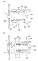
図1において、本発明の一実施形態を採用した両軸受リールは、レバードラグリールであり、筒状のリール本体1と、リール本体1の中心部に回転自在に装着されたスプール軸2と、スプール軸2に回転自在かつ軸方向移動不能に支持されたスプール3と、リール本体1の側方に配置されたハンドル4とを備えている。また、レバードラグリールは、ハンドル4の回転をスプール3に伝達する回転伝達機構6と、スプール3の糸繰り出し方向の回転を制動するレバードラグ機構7と、スプール3をロックするスプールロック機構8と、レバードラグ機構7の糸繰り出し方向の回転を規制する逆転防止機構9とをリール本体1の内部に備えている。
【0019】
〔リール本体の構成〕
リール本体1は、金属製の左右1対の皿状の側板10,11と、側板10,11が両端にいんろう結合により同芯に結合され複数本の固定ボルト13により固定された金属製の孔あき筒状のリールボディ12とを有している。側板10,11とリールボディ12との間には、リールを体で支えるために使用する1対のハーネスラグ14が装着されている。側板10,11は、そのほぼ中心部で回動自在にスプール軸2の両端を支持する。左側の側板10の中心部内側面には内方に突出する筒状の軸受収納部10aが形成されている。また、左側の側板10のいんろう結合部分の内周部10dは、固定ボルト13を避ける状態で内周部をアンダーカット加工して肉盗み処理を行っている。これにより、リール本体1の軽量化を図っている。右側(ハンドル4側)の側板11の中心部には、スプール軸2を支持するために軸方向外方に突出するボス部11aが形成されており、ボス部11aの周囲には、ハンドル4のハンドル軸5を装着するための厚肉円板状の軸受ブロック15がねじ止めされている。リールボディ12の下部にはリールを釣り竿に装着するための竿取付部19が設けられている。
【0020】
スプール軸2は、両端に配置された左右1対の軸受31a,31bによりリール本体1の側板10,11に回転自在に支持されている。またその内側で軸方向に間隔を隔ててスプール3の両端に配置された2つの軸受32a,32bによりスプール3を回転自在に支持する。左側の軸受31aは、左側の側板10に形成された軸受収納部10aに収納されている。右側の軸受31bは、右側の側板11に形成されたボス部11aに装着されている。スプール軸2の右端の軸受31bの外輪の右側にはレバードラグ機構7のドラグ移動機構38(後述)の構成部品が当接している。また内輪の左側には回転伝達機構6のピニオンギア17(後述)が当接している。スプール軸2の左端の軸受31aの内輪の右側には逆転防止機構9が当接している。また外輪の左端には、側板10の内側面が当接している。スプール3を支持する右側の軸受32bの外輪の左側にはスプール3が当接している。また内輪の右側にはワッシャ(図示せず)を介して4枚の皿ばね34が当接している。この皿ばね34は、制動操作レバー(後述)の揺動に対してドラグ力を急激に上昇させることなく広範囲でドラグ力を調整可能にするために設けられている。スプール3を支持する左側の軸受32aの内輪の左側にはレバードラグ機構7の後述する摩擦ディスク36がリターンばね47を介して当接している。外輪の右側はスプール3に当接している。
【0021】
スプール3は、糸巻胴部3aと糸巻胴部3aの両端に一体形成されたフランジ部3bとを有している。図1の右側(ハンドル装着側)のフランジ部3bの外方には、スプールロック機構8が設けられている。また、図1の左側のフランジ部3bの外方には、レバードラグ機構7の制動ディスク35が装着されている。この制動ディスク35をカバーするためのカバー部材39を取り付けるために、左側のフランジ部3bの外周部は、スプール軸方向外方に延びる筒状部3dが形成されている。筒状部3dの内周面3eは、アンダーカット加工して肉盗み処理されている。これにより、スプール3の軽量化を図れスプール3の慣性が減少する。
【0022】
〔スプールロック機構の構成〕
スプールロック機構8は、スプール3を糸巻取方向の回転を許容し、糸繰り出し方向の回転をロックする機構であり、図2に示すように、リール本体1の後部近傍に配置されている。スプールロック機構8は、図3及び図4に示すように、リール本体1に進出位置(図4(A))と退入位置(図4(B))とに移動自在に装着されたロック部21と、ロック部21を進出位置と退入位置とに移動させるロック移動機構22と、フランジ部3bの外側面に設けられ、進出位置に進出したロック部21の先端が係合可能なロック凹部23とを備えている。
【0023】
ロック部21は、側板11に固定された収納部材24にスプール軸2と平行な軸に沿って移動自在に装着された移動部材25を有している。移動部材25は、棒状部材であり、先端側からロック突起25a、鍔部25b、軸部25c及び面取り部25dを有している。ロック突起25aは、ロック凹部23に係合する突起であり、図4に矢符で示すスプール3の糸繰り出し方向の上流側が鋭角で下流側が鈍角に形成されている。このように形成されたロック突起25aは、ロック凹部23に係止されるとき、鋭角側にロック凹部23が接触すると、移動部材25が多少傾いてもロック凹部23に確実に食い込んでスプール3がロックされ、鈍角側にロック凹部23が接触すると、ロック凹部23の作用により移動部材25が退入可能である。鍔部25bは、ロック移動機構22を構成するコイルばね26を係止するためのものである。コイルばね26は、収納部材24の内部で移動部材25の軸部25cの外周側に配置されている。コイルばね26は、移動部材25をロック凹部23側に付勢する。軸部25cは、収納部材24に軸方向移動自在に支持されている。また面取り部25dにより収納部材24に回転不能に係止されている。すなわち、収納部材24には、一端に面取り部25dを係止可能な小判孔24aが形成されている。これにより、移動部材25は、リール本体1に軸方向移動自在かつ回転不能に装着される。移動部材25の面取り部25dの後端部には、径方向に沿って貫通孔25eが形成されている。貫通孔25eには、ロック移動機構22を構成するカムピン30が装着されている。このカムピン30により移動部材25の進出位置側の位置決めもなされている。上記のような形状のロック突起25aとコイルばね26による押圧とにより、進出位置に移動した移動部材25がロック凹部23に係合すると、糸巻取方向の回転が許容され、糸繰り出し方向の回転がロックされる。
【0024】
ロック凹部23は、ロックプレート28に回転方向に沿って間隔を隔てて形成された切欠きにより構成されている。ロックプレート28は、スプール3の図1右側のフランジ部3bの外側面に固定されたリング状のプレートである。スプール3のフランジ部3bのロック凹部23が形成された外側面には、ロック凹部23に対向した位置に環状に凹んだ逃がし部3cが形成されている。このような逃がし部3cを形成することにより、移動部材25のロック突起25aがロック凹部23を貫通することができる。
【0025】
ロック移動機構22は、側板11に移動部材25の軸回りに揺動自在に装着されたロックレバー27と、前述したコイルばね26と、ロックレバー27の揺動に応じて移動部材25をコイルばね26の付勢力に抗して進出位置から退入位置に移動させるロックカム機構29とを有している。ロックレバー27は、図2に示すように、進出位置に応じた二点鎖線で示した進出姿勢と退入位置に応じた実線で示す退入姿勢とにトグルばね37により付勢されている。ロックカム機構29は、ロックレバー27の基端部内側壁面に螺旋状に形成された傾斜カム面27aと、移動部材25の後端部に傾斜カム面27aに係合するように装着されたカムピン30とを有している。
【0026】
ハンドル4は、図1及び図2に示すように、スプール軸2の下方にスプール軸2と平行に配置された筒状のハンドル軸5の突出端に固定ボルト60により固定されている。固定ボルト60には、鍔部60aが形成されている。鍔部60aには、円弧状の12の凹部60bが周方向に間隔を隔てて形成されており、凹部60bに頭部が係合するビス61により回り止めされている。ハンドル軸5は、ボス部11aの前下方で軸受ブロック15にはめ込まれた筒状部材15aに回転自在に装着されている。ハンドル軸5の先端には、メインギア16が回転不能に装着されている。
【0027】
回転伝達機構6は、図1に示すように、ハンドル4のハンドル軸5に回転自在に支持されたメインギア16及びスプール軸2に一体形成されたピニオンギア17とを有している。ハンドル4の回転は、ハンドル軸5、メインギア16、ピニオンギア17を介してスプール軸2に伝達される。
【0028】
レバードラグ機構7は、図1に示すように、スプール3の図1左側のフランジ部3bの外側面に装着された制動ディスク35と、制動ディスク35に接触可能に配置された摩擦ディスク36と、スプール3及び摩擦ディスク36をスプール軸方向に往復移動させるためのドラグ移動機構38とを有している。
【0029】
制動ディスク35は、たとえばステンレス製のワッシャ状の円板部材であり、径方向内方の側面に周方向に間隔を隔てて配置された複数本の取付ねじ40により、スプール3の左側のフランジ部3bの外側面にスプール3に対して回転不能に装着されている。制動ディスク35の取付ねじ40の取付部35aは、径方向外方部分より環状に凹んでいる。これにより、ドラグ面積、特に径方向外方のドラグ面積が制限されにくくなり、スプール3の外径に応じた最大径の制動ディスク35を使用可能になる。
【0030】
摩擦ディスク36は、制動ディスク35と対向して配置されている。摩擦ディスク36の制動ディスク35に対向する面には、たとえばカーボングラファイトや繊維強化樹脂などの耐摩耗素材製のリング状の摩擦板36aがビス等の適宜の固定手段により固定されている。摩擦ディスク36は、中心部に軸方向外方に突出する筒状のボス部36bを有しており、このボス部36bにスプール軸2の径方向に沿って貫通してスプール軸2に装着されたピン2aが係止されている。これにより摩擦ディスク36は、スプール軸2に回転不能に装着されており、スプール軸2とともに回転する。また、摩擦ディスク36のボス部36bの図1左端面には逆転防止機構9のラチェットホイール50が回転不能かつ軸方向移動自在に装着されている。また、摩擦ディスク36は、カバー部材39により覆われている。摩擦ディスク36のボス部36bは、カバー部材39を貫通して軸受31a側に延びている。カバー部材39の貫通部分とボス部36bとの間にはシール部材39aが介装されている。
【0031】
〔逆転防止機構の構成〕
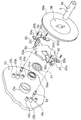
逆転防止機構9は、図5及び図6に示すように、外周面に鋸歯50aが形成されたラチェットホイール(回転部材の一例)50と、ラチェットホイール50の外周側に配置され先端が鋸歯50aを係止する1対のラチェット爪(爪部材の一例)51とを有する爪式のワンウェイクラッチである。
【0032】
ラチェットホイール50は、摩擦ディスク36のボス部36bの外周面にたとえばセレーションなどの適宜の係止手段により回転不能かつ軸方向外方(図1左方)に移動自在に装着されている。この結果、ラチェットホイール50は、スプール軸(連動部材の一例)2に摩擦ディスク36を介して回転不能かつ軸方向移動自在に装着されている。ラチェットホイール50は、図1左側面に同芯に装着されたリング状の当接部材54を有している。当接部材54は、軸受31aの内輪の右側端面に当接するとともに、軸受収納部10aの内周面に近接して配置される位置決め部54aを外周面に有している。このような当接部材54を設けると、ラチェットホイール50を側板10に対して芯出しして装着可能になるので、ラチェットホイール50の組み立てが容易である。なお、軸受31aの外輪は前述したように側板10に当接している。
【0033】
ラチェットホイール50は、1対の抜け止め部材55により側板10に対して抜け止めされている。抜け止め部材55は、側板10に固定された、たとえばステンレス合金製等の金属製の板状部材であり、一端部55aが側板10に固定されている。抜け止め部材55には、一端部55aからクランク状に摩擦ディスク36側に折れ曲がってラチェット爪51をまたぐ中央部55bが形成され、さらに側板10側にクランク状に折れ曲がって固定部55cが形成されている。この固定部55cでも側板10に固定されている。さらに固定部55cからラチェットホイール50側に湾曲してクランク状に折れ曲がって他端部55dが形成されている。他端部55dは、ラチェットホイール50の摩擦ディスク36側の側面に対向した位置に配置されている。この他端部55dによりラチェットホイール50が抜け止めされる。また、中央部55bでラチェット爪51の軸方向の移動が規制されて抜け止めされる。
【0034】
1対のラチェット爪51は、スプール軸芯に対して点対称の位置に配置されており、側板10の内側面に鋸歯50aに接触する接触姿勢と鋸歯50aから離反する離反姿勢とに揺動自在に装着されている。ラチェット爪51の先端は、揺動軸芯よりラチェットホイール50の糸巻取方向Rの下流側に配置されている。側板10には、ラチェット爪51を揺動自在に装着するための1対の爪ボス10bが軸受収納部10aを挟んで対称な位置に形成されている。また、1対の爪ボス10bを挟んで2つの取付ボス10cが形成されている。爪ボス10bには、ラチェット爪51を揺動自在に側板10に装着するための揺動ピン53が装着されている。揺動ピン53も、抜け止め部材55により軸方向の移動が規制され抜け止めされている。2つの取付ボス10cは、抜け止め部材55を一端部55aと固定部55cとで側板10にねじ止め固定するために設けられている。
【0035】
ラチェット爪51の中間部には、C字状に折り曲げられた挟持部材(付勢手段の一例)52がはめ込み固定されている。挟持部材52の1対の先端52aは、ラチェットホイール50の両側面に弾性的に接触してラチェットホイール50を挟持している。この挟持部材52は、ラチェットホイール50が糸巻取方向Rに回転すると、ラチェットホイール50との摩擦によりラチェット爪51を離反姿勢側に付勢する。付勢されたラチェット爪51は、抜け止め部材55に接触して離反姿勢に維持される。また、ラチェットホイール50が逆に糸繰り出し方向に回転すると、ラチェットホイール50との摩擦によりラチェット爪51を接触姿勢側に付勢する。これにより、糸巻取時にラチェット爪51がラチェットホイール50の鋸歯50aに接触しなくなり、騒音を抑えることができる。しかも、回転抵抗の増加を抑え、スプール3の巻取効率の低下を抑えることもできる。
【0036】
この結果、摩擦ディスク36は、スプール軸方向外方(図1左方)つまり制動ディスク36から離反する方向へ移動不能であるとともに、逆転防止機構9により糸巻取方向の回転が許可され糸繰り出し方向の回転が禁止される。
【0037】
ここで、制動解除状態にあるとき、図1のスプール軸芯の下側に示すように、摩擦ディスク36の摩擦板36aと制動ディスク35との間に隙間があき、制動状態にあるときには、図1のスプール軸芯の上側に示すように、両者が密着する。この密着度合いを調整することによりドラグ力が変化する。
【0038】
ドラグ移動機構38は、図1に示すように、リール本体1に揺動自在に設けられた制動操作レバー45と、制動操作レバー45の図2時計回りの揺動に応じてスプール3及び制動ディスク35を押圧して図1左方に移動させる押圧機構46と、摩擦ディスク36とスプール3との間に配置され、制動操作レバー45の図2反時計回りの移動に応じてスプールを図1右方に移動させるためのリターンばね47とを有している。
【0039】
リターンばね47は、摩擦ディスク36と軸受32aとの間においてスプール軸2の外周側に圧縮状態で装着され、摩擦ディスク36は制動ディスク35(スプール3)を離反する方向に付勢しかつ制動ディスク35(スプール3)を図1右方に付勢する。
【0040】
制動操作レバー45は、図2に実線で示す制動解除位置と2点鎖線で示す最大制動位置との間でリール本体1に揺動自在に装着されている。制動操作レバー45は、ボス部11aに揺動自在に装着されるレバー部45aと、レバー部45aの先端に固定されたつまみ部45bとを有している。レバー部45aの基端部は、押圧機構46に回転不能に係止されている。
【0041】
次にレバードラグ機構7の制動動作について説明する。
【0042】
レバードラグ機構7では、制動操作レバー45を図2に2点鎖線で示す制動位置から実線で示す制動解除位置に揺動させると、図1のスプール軸芯の上側に示す状態から下側に示す状態に変化する。まず、リターンばね47の付勢力によりスプール3が押圧されて図1右側に移動する。これにより、制動ディスク35と摩擦ディスク36との間に隙間ができる。さらに軸受32aを介してスプール3が押圧され右側に移動する。これによりスプール3の制動が解除される。一方、スプール3が移動すると、軸受32b、皿ばね34、ピニオンギア17及び軸受31bを介して押圧機構が押圧されて図1右側に後退する。そして、制動操作レバー45が制動解除位置に揺動すると図1のスプール軸芯の下側の状態に移動する。
【0043】
一方、制動操作レバー45を図2に実線で示す制動解除位置から2点鎖線で示す制動位置に揺動させると、図1のスプール軸芯の下側に示す状態から上側に示す状態に変化する。まず、制動操作レバー45の揺動により押圧機構46がスプール軸方向左方に移動する。これにより軸受31bの外輪が押圧されて移動し、ピニオンギア17、皿ばね34及び軸受32bを介してスプール3が押圧されスプール軸方向左方(図1左方)に移動する。この結果、制動ディスク35も軸方向左方に移動する。この結果、制動ディスク35が摩擦ディスク36に接近する。そして、制動ディスク35が、軸方向に移動不能でかつ糸繰り出し方向に回転不能な摩擦ディスク36に接触すると、ドラグ力がスプール3に作用する。そして、制動操作レバー45を最大揺動位置まで揺動させると、押圧力が最大になり、制動ディスク35が摩擦ディスク36により押圧されて大きなドラグ力が得られる。
【0044】
この状態でハンドル4の回転によりスプール3が糸巻取方向に回転すると、摩擦ディスク36を介してラチェットホイール50も糸巻取方向R(図5)に回転する。すると、挟持部材52は、ラチェットホイール50との摩擦により、糸巻取方向Rに引っ張られる。この結果、ラチェット爪51は挟持部材52によって離反姿勢側に付勢され、離反姿勢に揺動して抜け止め部材55に当接する。このため、スプール3が糸巻取方向に回転する時には、ラチェットホイール50とラチェット爪51との衝突によるクリック音は発生しない。
【0045】
一方、仕掛けに魚がかかってスプール3が糸繰り出し方向に回転すると、ラチェットホイール50も糸繰り出し方向に回転する。すると、挟持部材52は、ラチェットホイール50との摩擦により、糸巻取方向Rと逆の糸繰り出し方向に引っ張られる。この結果、ラチェット爪51は挟持部材52によって接触姿勢側に付勢され、接触姿勢に揺動する。このため、スプール3が糸繰り出し方向に回転する時には、ラチェットホイール50の糸繰り出し方向の回転が禁止される。この結果、摩擦ディスク36の糸繰り出し方向の回転が阻止されてスプール3に設定されたドラグ力が作用する。
【0046】
次に、レバードラグリールの操作方法について説明する。
【0047】
スプールに釣り糸を巻き取る際には、ハンドル4を糸巻取方向に回転させる。すると、ハンドル4の回転が、ハンドル軸5、メインギア16、ピニオンギア17、スプール軸2、レバードラグ機構7を介してスプール3に伝達され、スプール3が回転する。
【0048】
一方、仕掛けが根掛かりなどしたときにスプール3をロックさせる場合には、ロックレバー27を図2に実線で示す位置から2点鎖線で示す位置に揺動させる。すると、コイルばね26により付勢された移動部材25が進出位置側に進出し、ロック突起25aがロック凹部23に係止され、スプール3の糸繰り出し方向への回転がロックされる。この状態で釣り糸を巻き取って糸ふけを取った後、釣り竿を仕掛けに向けてまっすく引っ張る。こうすることによって根掛かりした相手物、釣り針、釣り糸、あるいはその結束部が破損して仕掛け又は仕掛けの一部を回収することができる。
【0049】
このとき、移動部材25は、鍔部25bと軸部25cとが収納部材24に接触して力を受ける。このロック時には、スプール3に設けられたロック凹部23に移動部材25を係合することによりスプール3をロックしているので、スプール3を直接ロックすることができ、無理な力が作用してもスプールロック機構8が破損や変形しにくくなる。また、ロック凹部23がフランジ部3bの外側面に設けられているので、釣り糸を繰り出した状態では通常は釣り糸の巻径と同じか又はそれより大径部分にロック凹部23が配置される。このため、移動部材25に作用する力が釣り糸の張力と同等か又はそれより小さくなる。したがって、スプールロック機構8がさらに破損や変形しにくくなる。
【0050】
また、ロック突起25aが前述したように糸繰り出し方向下流側が鈍角になっており、かつ移動部材25がコイルばね26により付勢されているので、スプール3が糸巻取方向に回転すると、移動部材25がロック凹部23により押圧されて退入位置側に移動する。したがって、スプールロック中に誤ってスプール3を糸巻取方向に回転させても回転伝達機構6などに無理な力が作用しない。
【0051】
一方、リールのメンテナンスのためなどにスプール3とともにスプール軸2を抜くと、ラチェットホイール50が、グリースの粘性や摩擦によりスプール軸2とともに軸方向に移動することがある。しかし、ここでは、抜け止め部材55によりラチェットホイール50は抜け止めされている。このため、ラチェットホイール50は、スプール3とともにスプール軸2を外してもボス部36bから外れて側板10側に残るようになっている。したがって、スプール軸2を脱着する際に、ラチェット爪51に装着された挟持部材52が変形したり損傷することがない。
【0052】
〔他の実施形態〕
(a) 前記実施形態では、スプール軸が連動部材であるレバードラグ式のドラグ機構に用いられる逆転防止機構を例に説明したが、ハンドル軸が連動部材であるスタードラグ式のドラグ機構に用いられる逆転防止機構にも本発明を適用できる。
【0053】
(b) 前記実施形態では、ラチェットホイール50の両側面を挟持する挟持部材により付勢手段を構成したが、付勢手段は、スプール側の片面だけに接触するものであってもよい。
【0054】
(c) 前記実施形態では、摩擦ディスク36を介してラチェットホイール50をスプール軸2に回転不能かつ軸方向移動自在に装着したが、スプール軸2に直接装着してもよい。
【0055】
【発明の効果】
本発明によれば、回転部材が連動部材に軸方向移動自在に装着されているとともに、抜け止め手段によりリール本体に対して抜け止めされている。このため、連動部材の脱着時に回転部材がリール本体側に残り軸方向に移動しない。したがって、連動部材の脱着時に爪部材に装着された付勢部材が変形しにくくなる。
【図面の簡単な説明】
【図1】 本発明の一実施形態によるレバードラグリールの断面図。
【図2】 その側面図。
【図3】 スプールロック機構の分解斜視図。
【図4】 スプールロック機構の断面図。
【図5】 逆転防止機構の正面図。
【図6】 逆転防止機構の分解斜視図。
【符号の説明】
1 リール本体
2 スプール軸
3 スプール
9 逆転防止機構
36 摩擦ディスク
50 ラチェットホイール
50a 鋸歯
51 ラチェット爪
52 挟持部材
54 当接部材(位置決め手段)
54a 位置決め部
55 抜け止め部材[0001]
BACKGROUND OF THE INVENTION
The present invention relates to a reverse rotation prevention mechanism, and more particularly to a reverse rotation prevention mechanism for a dual-bearing reel for restricting the rotation of a spool that is rotatably mounted on a reel body of the dual-bearing reel in the yarn unwinding direction.
[0002]
[Prior art]
In general, a drag device for a dual-bearing reel is equipped with a reverse rotation prevention mechanism for prohibiting rotation of an interlocking member that can be interlocked with a spool during the drag operation in the yarn unwinding direction. For example, in the case of a star drag type drag device provided around the handle shaft, a reverse rotation prevention mechanism is mounted on the handle shaft. In the case of a lever drag type drag device provided around the spool shaft, a reverse rotation prevention mechanism is provided on the spool shaft or drag disk.
[0003]
In general, a claw-type reverse rotation prevention mechanism is used as a reverse rotation prevention mechanism used in this type of lever drag reel braking device. The claw-type reverse rotation prevention mechanism has a tooth portion formed on the outer peripheral portion with a gap in the circumferential direction, and is separated from a rotating member that is non-rotatably mounted on the interlocking member and a contact posture that contacts the tooth portion of the rotating member. A claw member mounted on the reel body so as to be swingable between the separated postures, and a biasing member that biases the claw members toward the contact posture side. The tip of the claw member is disposed downstream of the swing center in the yarn winding direction.
[0004]
In the claw-type reverse rotation prevention mechanism configured as described above, when the rotating member rotates in the yarn winding direction in conjunction with the rotation of the spool in the yarn winding direction, the claw member is pressed toward the separation posture by the tooth portion. However, when the tooth portion passes through the claw member, it is urged toward the contact posture by the urging member and contacts the rotating member. For this reason, when the spool rotates in the yarn winding direction, the pawl member comes into contact with the rotating member in a vibrating state, and an intermittent click sound is generated. When such a click sound is generated, for example, when fishing such as jigging that frequently repeats the winding operation is performed, the noise becomes unpleasant continuously. Moreover, since the claw member comes into contact with the rotating member, the rotational resistance at the time of winding also increases, and the winding efficiency also decreases.
[0005]
Therefore, in order to eliminate the click sound at the time of winding the yarn, there is known one provided with a biasing member that biases the claw member by friction instead of biasing by a spring. The urging member is composed of a thin plate member bent in a C-shape, and is fitted and fixed to the claw member. A pair of front ends of the urging members elastically contact both side surfaces of the rotating member to sandwich the rotating member. In the reverse rotation prevention mechanism having such a biasing member due to friction, when the rotating member rotates in the yarn winding direction, the claw member is biased toward the separating posture side by friction, and when rotating in the yarn unwinding direction, the contact posture side is caused by friction. Be energized by. For this reason, no click sound is generated when winding the yarn.
[0006]
[Problems to be solved by the invention]
In the conventional reverse rotation preventing mechanism, when the interlocking member such as the handle shaft or the spool shaft is pulled out for disassembly for maintenance or replacement of parts, the rotating member may move together with the interlocking member. When the rotating member moves together with the interlocking member, the biasing member holding the rotating member may be deformed. In order to prevent this, the rotating member may be disposed so as to be relatively movable in the axial direction with respect to the interlocking member.
[0007]
However, even if the rotating member is movably arranged in this way, the rotating member may move even slightly due to the movement of the interlocking member due to the influence of a lubricant such as grease or the influence of friction. Even with such a slight movement, the urging member made of a relatively thin plate material may be deformed.
[0008]
When the urging member is deformed, a frictional force is not generated between the urging member and the rotating member, and the claw member cannot be normally urged. As a result, the reverse rotation prevention mechanism does not operate normally.
[0009]
The subject of this invention is suppressing the deformation | transformation of an urging | biasing member in the reverse rotation prevention mechanism provided with the urging | biasing member which urges | biases a nail | claw member by friction with a rotating member.
[0010]
[Means for Solving the Problems]
A mechanism for preventing reverse rotation of a dual-bearing reel according to a first aspect of the invention is a mechanism for restricting rotation of a spool, which is rotatably mounted on a reel body of the dual-bearing reel, in a yarn unwinding direction, and includes a rotating member, a claw member, And a retaining means and a biasing means. The rotating member is a member that has a plurality of tooth portions formed on the outer peripheral portion at intervals in the circumferential direction, and is attached to an interlocking member that can be interlocked with the spool so as to be axially movable and non-rotatable. The claw member is swingably mounted on the reel body in a contact posture in which the tip contacts the tooth portion and a separation posture in which the tooth portion is separated from the tooth portion, and when arranged in the contact posture, rotation of the rotating member in the thread unwinding direction is prohibited. It is a member to do. The retaining means is a means that is provided in the reel body and prevents the rotating member from being detached from the reel body. The urging means is a means that is attached to the claw member and urges the claw member toward the separating posture when the rotating member rotates in the yarn winding direction, and urges the claw member toward the contact posture when rotated in the yarn feeding direction.
[0011]
In this reverse rotation prevention mechanism, when the spool rotates in the yarn winding direction due to the rotation of the handle in the yarn winding direction, the rotating member also rotates in the yarn winding direction. Then, the claw member is urged toward the separation posture by the urging means, the claw member does not collide with the rotating member, and no click sound is generated. Further, when the spool rotates in the yarn unwinding direction and the rotating member tries to rotate in the yarn unwinding direction, the urging means urges the claw member toward the contact position side and the rotation of the rotating member in the thread unwinding direction is prohibited. The drag is activated. When such a reverse rotation prevention mechanism is disassembled by maintenance work or the like, the rotating member is attached to the interlocking member so as to be movable in the axial direction, and is prevented from being detached from the reel body by the retaining means. For this reason, the rotating member does not move to the reel body side in the remaining axial direction when the interlocking member is detached. Therefore, the urging member attached to the claw member is less likely to be deformed when the interlocking member is detached.
[0012]
An anti-reverse rotation mechanism for a dual-bearing reel according to a second aspect of the present invention is the mechanism according to the first aspect, wherein the urging means includes a clamping member that is provided on the claw member and elastically clamps both side surfaces of the rotating member. In this case, even if both side surfaces of the rotating member are elastically clamped, the clamping member is difficult to be deformed when the interlocking member is detached. In addition, since both sides of the rotating member are clamped and urged, the reliability of the urging operation is improved.
[0013]
According to a third aspect of the present invention, there is provided the mechanism for preventing the reverse rotation of the dual-bearing reel according to the first or second aspect, wherein the retaining means prevents the claw member from coming off from the reel body. In this case, since the claw member is prevented from coming off in addition to the rotating member, the swing support structure for the claw member to the reel body is simplified.
[0014]
The dual-bearing reel reverse rotation preventing mechanism according to a fourth aspect of the present invention is the mechanism according to any one of the first to third aspects, wherein the rotating member is arranged on the reel body so that the rotating shaft core of the rotating member and the rotating shaft core of the interlocking member are aligned. Further, positioning means capable of positioning with respect to each other is provided. In this case, since the positioning is performed when the rotating member is mounted on the reel body, it is easy to incorporate the rotating member.
[0015]
According to a fifth aspect of the present invention, there is provided the mechanism for preventing the reverse rotation of the dual-bearing reel according to any one of the first to fourth aspects, wherein the retaining means is fixed to the reel body and one end is on the side opposite to the reel body of the rotating member. It is the plate-shaped member arrange | positioned in the position which opposes. In this case, since the retaining means is composed of a plate-like member, the structure of the retaining means is simple.
[0016]
According to a sixth aspect of the present invention, in the mechanism for preventing the reverse rotation of the dual-bearing reel according to any of the first to fifth aspects, the interlocking member is a spool shaft that rotatably supports the spool. In this case, in the reverse rotation prevention mechanism used in the lever drag type drag mechanism, the urging member can be prevented from being deformed.
[0017]
According to a seventh aspect of the present invention, in the mechanism according to any one of the first to fifth aspects, the interlocking member is a handle shaft for rotating the spool. In this case, in the reverse rotation prevention mechanism used in the star drag type drag mechanism, the urging member can be prevented from being deformed.
[0018]
DETAILED DESCRIPTION OF THE INVENTION
〔overall structure〕
In FIG. 1, a dual-bearing reel employing an embodiment of the present invention is a lever drag reel, a
[0019]
[Reel body configuration]
The
[0020]
The
[0021]
The
[0022]
[Configuration of spool lock mechanism]
The spool lock mechanism 8 is a mechanism that allows the
[0023]
The
[0024]
The
[0025]
The
[0026]
As shown in FIGS. 1 and 2, the
[0027]
As shown in FIG. 1, the rotation transmission mechanism 6 includes a
[0028]
As shown in FIG. 1, the lever drag mechanism 7 is in contact with the
[0029]
The
[0030]
The
[0031]
[Configuration of reverse rotation prevention mechanism]
As shown in FIGS. 5 and 6, the reverse
[0032]
The
[0033]
The
[0034]
The pair of
[0035]
A clamping member (an example of an urging means) 52 bent into a C shape is fitted and fixed to an intermediate portion of the
[0036]
As a result, the
[0037]
Here, when the brake is released, there is a gap between the
[0038]
As shown in FIG. 1, the
[0039]
The return spring 47 is mounted in a compressed state on the outer peripheral side of the
[0040]
The
[0041]
Next, the braking operation of the lever drag mechanism 7 will be described.
[0042]
In the lever drag mechanism 7, when the
[0043]
On the other hand, when the
[0044]
In this state, when the
[0045]
On the other hand, when the fish is caught in the mechanism and the
[0046]
Next, a method for operating the lever drag reel will be described.
[0047]
When winding the fishing line on the spool, the
[0048]
On the other hand, when the
[0049]
At this time, the moving
[0050]
Further, as described above, the
[0051]
On the other hand, when the
[0052]
[Other Embodiments]
(A) In the above embodiment, the reverse rotation prevention mechanism used in the lever drag type drag mechanism in which the spool shaft is the interlocking member has been described as an example. However, it is used in the star drag type drag mechanism in which the handle shaft is the interlocking member. The present invention can also be applied to a reverse rotation prevention mechanism.
[0053]
(B) In the above-described embodiment, the urging means is configured by the clamping members that clamp the both side surfaces of the
[0054]
(C) In the above-described embodiment, the
[0055]
【The invention's effect】
According to the present invention, the rotating member is attached to the interlocking member so as to be movable in the axial direction, and is prevented from being detached from the reel body by the retaining means. For this reason, the rotating member does not move to the reel body side in the remaining axial direction when the interlocking member is detached. Therefore, the urging member attached to the claw member is less likely to be deformed when the interlocking member is detached.
[Brief description of the drawings]
FIG. 1 is a cross-sectional view of a lever drag reel according to an embodiment of the present invention.
FIG. 2 is a side view thereof.
FIG. 3 is an exploded perspective view of a spool lock mechanism.
FIG. 4 is a cross-sectional view of a spool lock mechanism.
FIG. 5 is a front view of a reverse rotation prevention mechanism.
FIG. 6 is an exploded perspective view of a reverse rotation prevention mechanism.
[Explanation of symbols]
1 Reel body
2 Spool shaft
3 Spool
9 Reverse rotation prevention mechanism
36 Friction disc
50 ratchet wheel
50a saw blade
51 ratchet claws
52 Clamping member
54 Contact member (positioning means)
54a Positioning part
55 Retaining member
Claims (7)
外周部に周方向に間隔を隔てて形成された複数の歯部を有し、前記スプールと連動可能な連動部材に軸方向移動自在かつ回転不能に装着された回転部材と、
前記歯部に先端が接触する接触姿勢と前記歯部から離反する離反姿勢とに前記リール本体に揺動自在に装着され、前記接触姿勢に配置されると前記回転部材の糸繰り出し方向の回転を禁止する爪部材と、
前記リール本体に設けられ、前記回転部材を前記リール本体に対して抜け止めする抜け止め手段と、
前記爪部材に装着され、前記回転部材との摩擦により前記回転部材が糸巻取方向に回転したとき前記爪部材を前記離反姿勢側に付勢し、前記糸繰り出し方向に回転したとき前記接触姿勢側に付勢する付勢手段と、
を備えた両軸受リールの逆転防止機構。A mechanism for preventing the reverse rotation of the dual-bearing reel for restricting the rotation of the spool, which is rotatably mounted on the reel body of the dual-bearing reel, in the yarn unwinding direction,
A rotating member having a plurality of teeth formed on the outer peripheral portion at intervals in the circumferential direction, and mounted on the interlocking member that can be interlocked with the spool in an axially movable and non-rotatable manner;
The reel body is swingably mounted in a contact posture in which the tip contacts the tooth portion and a separation posture in which the tooth portion is separated from the tooth portion, and when arranged in the contact posture, the rotation member rotates in the yarn unwinding direction. Forbidden claw members,
Retaining means provided on the reel body for retaining the rotating member with respect to the reel body;
The claw member is attached to the claw member and biases the claw member toward the separating posture when the rotating member rotates in the yarn winding direction due to friction with the rotating member, and the contact posture side when rotated in the yarn feeding direction. A biasing means for biasing to
A mechanism for preventing reverse rotation of a dual-bearing reel equipped with
Priority Applications (9)
| Application Number | Priority Date | Filing Date | Title |
|---|---|---|---|
| JP2000261523A JP4381580B2 (en) | 2000-08-30 | 2000-08-30 | Double bearing reel reverse rotation prevention mechanism |
| TW090114624A TW504368B (en) | 2000-08-30 | 2001-06-15 | Dual-bearing reel anti-reverse mechanism |
| KR1020010040247A KR100722538B1 (en) | 2000-08-30 | 2001-07-06 | Reverse rotation preventing device of double bearing reel |
| EP01307096A EP1183946B1 (en) | 2000-08-30 | 2001-08-21 | Dual-bearing reel anti-reverse mechanism |
| AT01307096T ATE279103T1 (en) | 2000-08-30 | 2001-08-21 | BACKLOCK FOR DOUBLE BEARING FISHING REELS |
| DE60106355T DE60106355T2 (en) | 2000-08-30 | 2001-08-21 | Backstop for double-bearing fishing reels |
| AU63593/01A AU779135B2 (en) | 2000-08-30 | 2001-08-22 | Dual-bearing reel anti-reverse mechanism |
| US09/934,517 US6517021B2 (en) | 2000-08-30 | 2001-08-23 | Dual-bearing reel anti-reverse mechanism |
| CNB011258934A CN1225165C (en) | 2000-08-30 | 2001-08-30 | Reversion-resisting mechanism of double-bearing wire winder |
Applications Claiming Priority (1)
| Application Number | Priority Date | Filing Date | Title |
|---|---|---|---|
| JP2000261523A JP4381580B2 (en) | 2000-08-30 | 2000-08-30 | Double bearing reel reverse rotation prevention mechanism |
Publications (3)
| Publication Number | Publication Date |
|---|---|
| JP2002065129A JP2002065129A (en) | 2002-03-05 |
| JP2002065129A5 JP2002065129A5 (en) | 2007-08-16 |
| JP4381580B2 true JP4381580B2 (en) | 2009-12-09 |
Family
ID=18749351
Family Applications (1)
| Application Number | Title | Priority Date | Filing Date |
|---|---|---|---|
| JP2000261523A Expired - Fee Related JP4381580B2 (en) | 2000-08-30 | 2000-08-30 | Double bearing reel reverse rotation prevention mechanism |
Country Status (9)
| Country | Link |
|---|---|
| US (1) | US6517021B2 (en) |
| EP (1) | EP1183946B1 (en) |
| JP (1) | JP4381580B2 (en) |
| KR (1) | KR100722538B1 (en) |
| CN (1) | CN1225165C (en) |
| AT (1) | ATE279103T1 (en) |
| AU (1) | AU779135B2 (en) |
| DE (1) | DE60106355T2 (en) |
| TW (1) | TW504368B (en) |
Families Citing this family (13)
| Publication number | Priority date | Publication date | Assignee | Title |
|---|---|---|---|---|
| JP4381733B2 (en) * | 2003-06-26 | 2009-12-09 | 株式会社シマノ | Double bearing reel |
| US6634586B1 (en) * | 2002-07-02 | 2003-10-21 | Liang-Jen Chang | Anti-reversional mechanism for trolling reel |
| US7198219B1 (en) * | 2005-05-27 | 2007-04-03 | Harout Alajajyan | Fishing reel transmission |
| US7128287B1 (en) * | 2005-11-10 | 2006-10-31 | Okuma Fishing Tackle Co. Ltd. | Fishing reel |
| GB2461876B (en) * | 2008-07-14 | 2011-03-09 | Lead Innovations | Retracting dog lead with manual override |
| KR101126546B1 (en) * | 2009-06-26 | 2012-03-26 | 주식회사 도요엔지니어링 | bait reel for fishing |
| JP5961378B2 (en) * | 2011-12-22 | 2016-08-02 | 株式会社シマノ | Drag adjusting device for double-bearing reel |
| JP6200287B2 (en) * | 2013-11-14 | 2017-09-20 | シマノコンポネンツ マレーシア エスディーエヌ.ビーエッチディー. | Double bearing reel |
| JP6467218B2 (en) * | 2014-12-19 | 2019-02-06 | 株式会社シマノ | Double bearing reel |
| JP6518514B2 (en) * | 2015-05-28 | 2019-05-22 | 株式会社シマノ | Double bearing reel |
| JP6886344B2 (en) * | 2017-05-17 | 2021-06-16 | 株式会社シマノ | Double bearing reel |
| JP7086827B2 (en) * | 2018-12-14 | 2022-06-20 | 株式会社シマノ | Fishing reel cap |
| CN113049487B (en) * | 2021-03-22 | 2022-03-18 | 北京航空航天大学 | Test system and method for calculating friction coefficient of inclined roller type friction disc |
Family Cites Families (7)
| Publication number | Priority date | Publication date | Assignee | Title |
|---|---|---|---|---|
| US3989204A (en) * | 1968-01-05 | 1976-11-02 | Carpano & Pons S.A. | Fly fishing reel |
| US4899953A (en) * | 1987-05-23 | 1990-02-13 | Shimano Industrial Company Limited | Double bearing fishing reel |
| US5201870A (en) * | 1990-12-14 | 1993-04-13 | Newell Carl W | Reverse stop rachet and pawl for a fishing reel |
| US5415359A (en) * | 1991-02-05 | 1995-05-16 | Ikuta; Takeshi | Fishing reel |
| JP2957882B2 (en) * | 1994-02-22 | 1999-10-06 | ダイワ精工株式会社 | Fishing reel |
| US6056223A (en) * | 1996-08-21 | 2000-05-02 | Kirby; Thomas Glen | Drag mounted spring for spin-cast reels |
| AUPO185596A0 (en) * | 1996-08-23 | 1996-09-19 | Jarvis Walker Pty Ltd | A spinning reel for fishing |
-
2000
- 2000-08-30 JP JP2000261523A patent/JP4381580B2/en not_active Expired - Fee Related
-
2001
- 2001-06-15 TW TW090114624A patent/TW504368B/en not_active IP Right Cessation
- 2001-07-06 KR KR1020010040247A patent/KR100722538B1/en active IP Right Grant
- 2001-08-21 AT AT01307096T patent/ATE279103T1/en not_active IP Right Cessation
- 2001-08-21 DE DE60106355T patent/DE60106355T2/en not_active Expired - Lifetime
- 2001-08-21 EP EP01307096A patent/EP1183946B1/en not_active Expired - Lifetime
- 2001-08-22 AU AU63593/01A patent/AU779135B2/en not_active Ceased
- 2001-08-23 US US09/934,517 patent/US6517021B2/en not_active Expired - Lifetime
- 2001-08-30 CN CNB011258934A patent/CN1225165C/en not_active Expired - Fee Related
Also Published As
| Publication number | Publication date |
|---|---|
| TW504368B (en) | 2002-10-01 |
| DE60106355T2 (en) | 2006-02-02 |
| US6517021B2 (en) | 2003-02-11 |
| AU6359301A (en) | 2002-03-07 |
| DE60106355D1 (en) | 2004-11-18 |
| AU779135B2 (en) | 2005-01-06 |
| US20020023978A1 (en) | 2002-02-28 |
| EP1183946B1 (en) | 2004-10-13 |
| KR100722538B1 (en) | 2007-05-28 |
| JP2002065129A (en) | 2002-03-05 |
| CN1341354A (en) | 2002-03-27 |
| ATE279103T1 (en) | 2004-10-15 |
| EP1183946A1 (en) | 2002-03-06 |
| KR20020017946A (en) | 2002-03-07 |
| CN1225165C (en) | 2005-11-02 |
Similar Documents
| Publication | Publication Date | Title |
|---|---|---|
| JP4381580B2 (en) | Double bearing reel reverse rotation prevention mechanism | |
| US7661618B2 (en) | Drag mechanism for dual-bearing reel | |
| EP1181864B1 (en) | Dual-Bearing reel spool-locking mechanism | |
| US7753304B2 (en) | Lever drag type dual-bearing reel | |
| US7163167B2 (en) | One way clutch for spinning reel | |
| US7866587B2 (en) | Drag adjusting mechanism for dual-bearing reel | |
| US20100006689A1 (en) | Sound generating device for dual-bearing reel | |
| JP4863716B2 (en) | Spinning reel rotor braking device | |
| KR102243481B1 (en) | Dual-bearing reel | |
| JP4451773B2 (en) | One-way clutch of double-bearing reel | |
| JP2007185130A5 (en) | ||
| JP2015092876A5 (en) | ||
| JP2006180777A5 (en) | ||
| JP4173387B2 (en) | Sounding mechanism of spinning reel | |
| JP4834240B2 (en) | Double-bearing reel drag adjustment mechanism | |
| JP2003009734A (en) | Double bearing reel | |
| JP4109779B2 (en) | Single bearing reel | |
| JP4834786B2 (en) | Double-bearing reel drag adjustment mechanism | |
| TW201336407A (en) | Spinning reel and drag switching device thereof | |
| JP2000125712A (en) | Spinning reel for fishing | |
| JP2001204322A (en) | One way clutch of lever drag reel | |
| JP2003047373A (en) | Reel main body of spinning reel |
Legal Events
| Date | Code | Title | Description |
|---|---|---|---|
| A521 | Request for written amendment filed |
Free format text: JAPANESE INTERMEDIATE CODE: A523 Effective date: 20070703 |
|
| A621 | Written request for application examination |
Free format text: JAPANESE INTERMEDIATE CODE: A621 Effective date: 20070703 |
|
| RD02 | Notification of acceptance of power of attorney |
Free format text: JAPANESE INTERMEDIATE CODE: A7422 Effective date: 20070703 |
|
| A977 | Report on retrieval |
Free format text: JAPANESE INTERMEDIATE CODE: A971007 Effective date: 20090807 |
|
| TRDD | Decision of grant or rejection written | ||
| A01 | Written decision to grant a patent or to grant a registration (utility model) |
Free format text: JAPANESE INTERMEDIATE CODE: A01 Effective date: 20090901 |
|
| A01 | Written decision to grant a patent or to grant a registration (utility model) |
Free format text: JAPANESE INTERMEDIATE CODE: A01 |
|
| A61 | First payment of annual fees (during grant procedure) |
Free format text: JAPANESE INTERMEDIATE CODE: A61 Effective date: 20090916 |
|
| FPAY | Renewal fee payment (event date is renewal date of database) |
Free format text: PAYMENT UNTIL: 20121002 Year of fee payment: 3 |
|
| R150 | Certificate of patent or registration of utility model |
Free format text: JAPANESE INTERMEDIATE CODE: R150 Ref document number: 4381580 Country of ref document: JP Free format text: JAPANESE INTERMEDIATE CODE: R150 |
|
| FPAY | Renewal fee payment (event date is renewal date of database) |
Free format text: PAYMENT UNTIL: 20131002 Year of fee payment: 4 |
|
| R250 | Receipt of annual fees |
Free format text: JAPANESE INTERMEDIATE CODE: R250 |
|
| R250 | Receipt of annual fees |
Free format text: JAPANESE INTERMEDIATE CODE: R250 |
|
| R250 | Receipt of annual fees |
Free format text: JAPANESE INTERMEDIATE CODE: R250 |
|
| R250 | Receipt of annual fees |
Free format text: JAPANESE INTERMEDIATE CODE: R250 |
|
| R250 | Receipt of annual fees |
Free format text: JAPANESE INTERMEDIATE CODE: R250 |
|
| R250 | Receipt of annual fees |
Free format text: JAPANESE INTERMEDIATE CODE: R250 |
|
| R250 | Receipt of annual fees |
Free format text: JAPANESE INTERMEDIATE CODE: R250 |
|
| LAPS | Cancellation because of no payment of annual fees |